• Hi all and welcome to TheWoodHaven2 brought into the 21st Century, kicking and screaming! We all have Alasdair to thank for the vast bulk of the heavy lifting to get us here, no more so than me because he's taken away a huge burden of responsibility from my shoulders and brought us to this new shiny home, with all your previous content (hopefully) still intact! Please peruse and feed back. There is still plenty to do, like changing the colour scheme, adding the banner graphic, tweaking the odd setting here and there so I have added a new thread in the 'Technical Issues, Bugs and Feature Requests' forum for you to add any issues you find, any missing settings or just anything you'd like to see added/removed from the feature set that Xenforo offers. We will get to everything over the coming weeks so please be patient, but add anything at all to the thread I mention above and we promise to get to them over the next few days/weeks/months. In the meantime, please enjoy!

Mixed Media - Making a wood & metal plane

Dr.Al

Old Oak
Joined
Dec 31, 2020
Messages
2,109
Reaction score
99
Location
Dursley, Gloucestershire
Name
Al
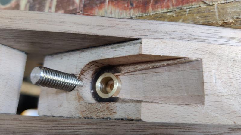
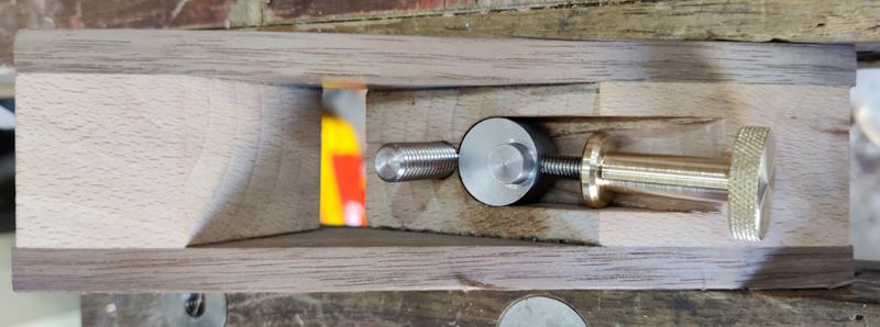
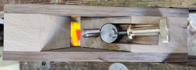
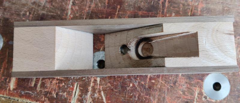
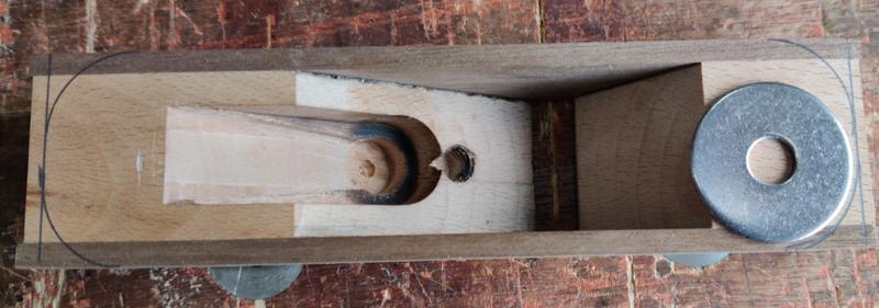
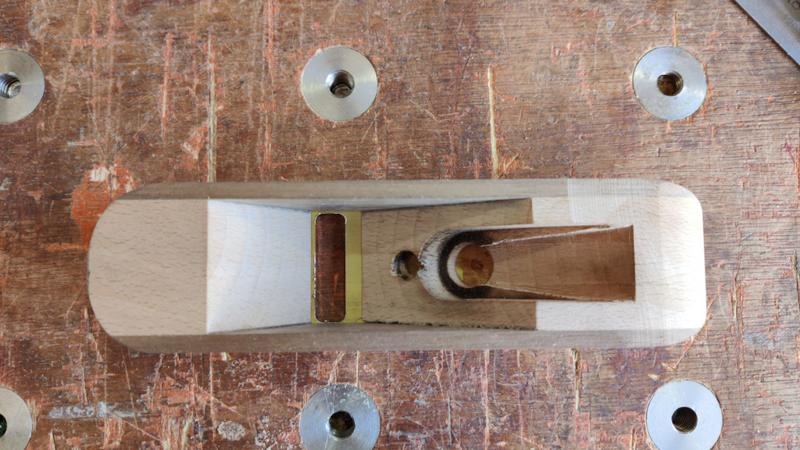
When making my Travel Tool Chest, I made a dedicated block plane to run in the track in the integrated shooting board. This is a photo of the plane:

previous_plane_800.jpg


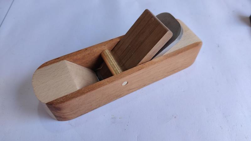
That's actually the fourth attempt at the plane. The first one was an attempt to make it out of a solid block of beech. I need more practice at chiselling before I can use that approach! The second one worked okay but had a habit of clogging up and was hard to clear due to having a much bigger cross-pin thing. On the third attempt I drilled a hole in the wrong place and that resulted in it becoming firewood. The fourth version (shown above) works well, but I've wanted to have a go at something a little more ambitious so I thought I'd try a fifth version. If the fifth version fails, I've still got the fourth version as a fall-back option!

At the time of writing this, I've mostly finished making the latest version, but I thought I'd post it in the form of a work-in-progress despite it no longer being in progress. I'll do one update a day or thereabouts to try to tell the story gradually (and not necessarily in the order that I actually made things as I'll describe one part at a time whereas in practice I alternated back and forth quite a bit).

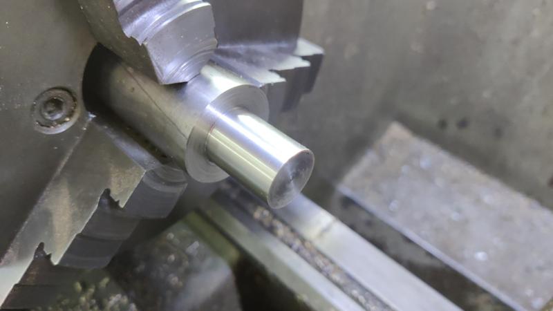
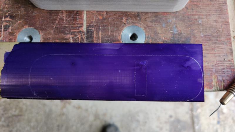
Materials to be used for version 5 are beech, American black walnut, brass, stainless steel and gauge plate (tool steel). Let's start with the blade, made out of 5 mm × 30 mm gauge plate.

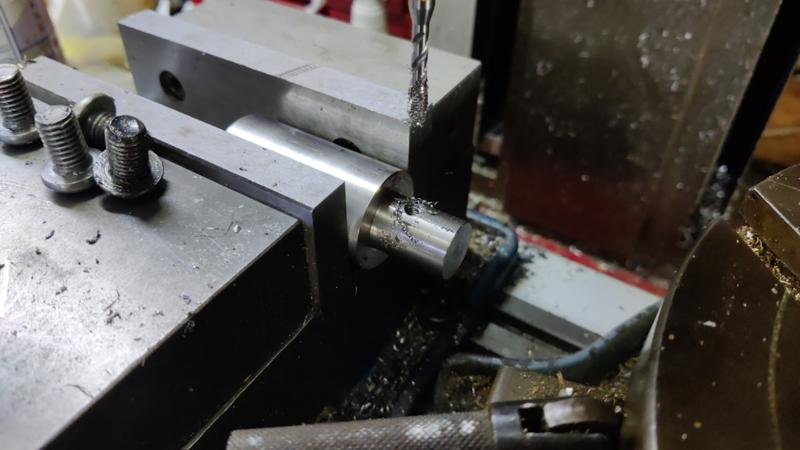
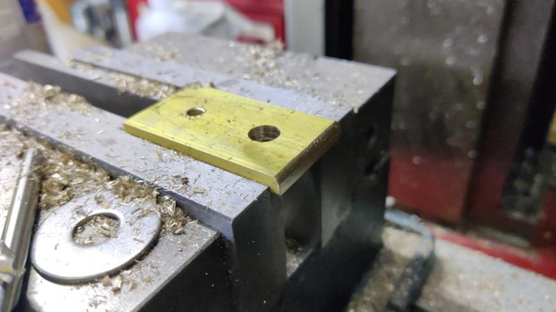
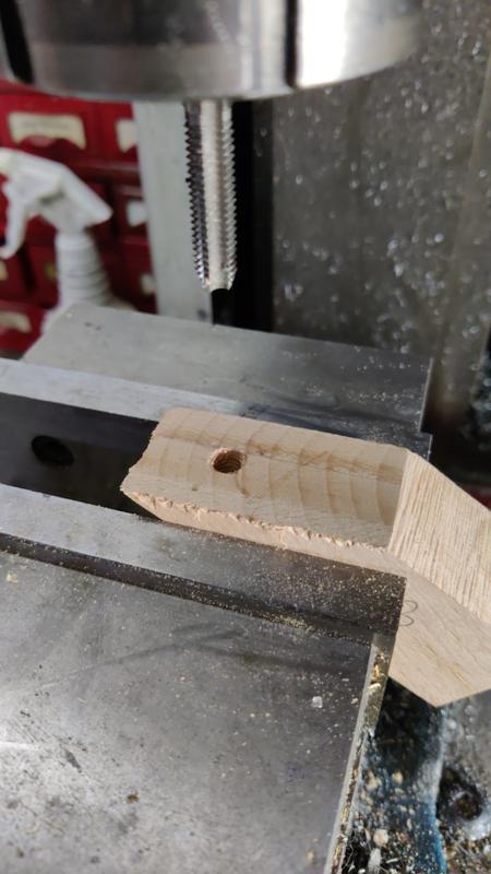
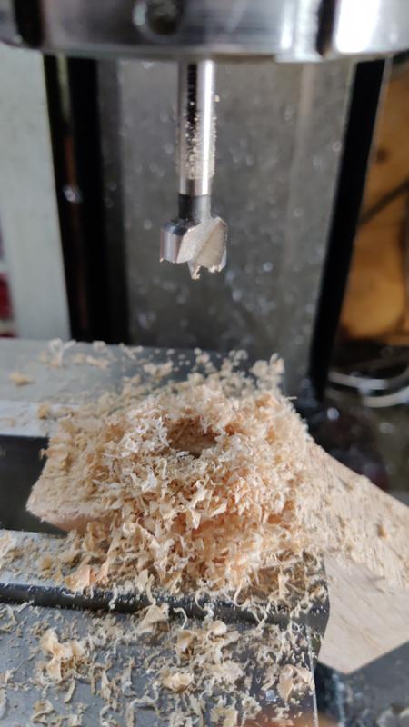
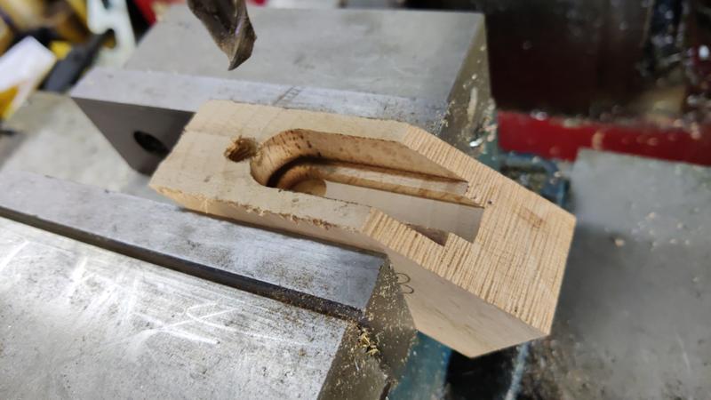
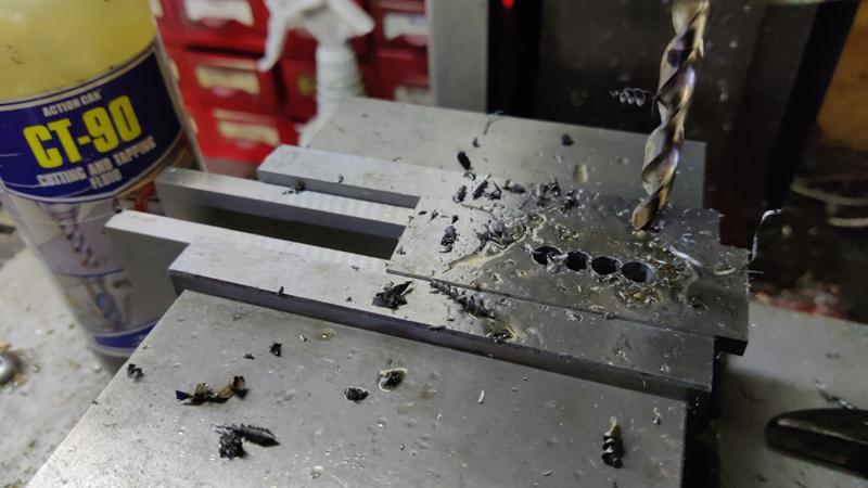
I started by mounting the gauge plate blank in the milling vice and drilling a series of 7 mm holes:

blade_01_drilling_slot_holes_800.jpg


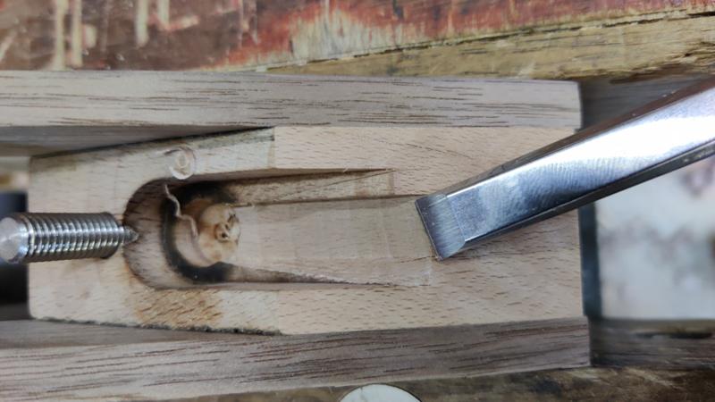
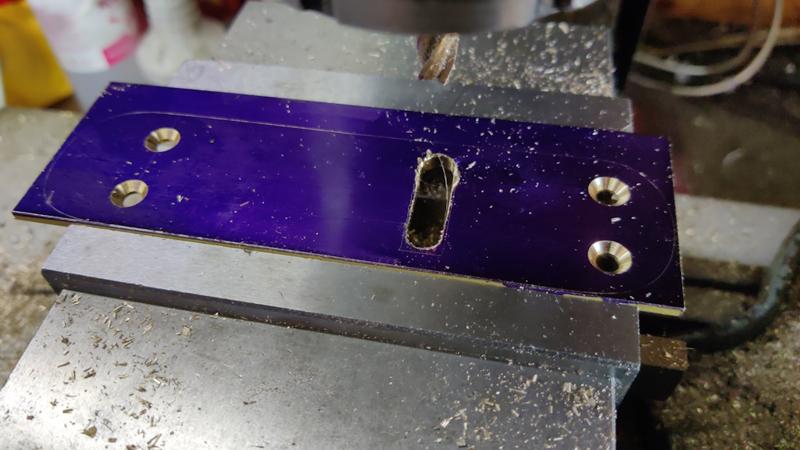
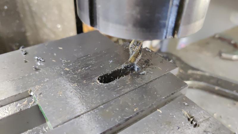
An end mill was then used to join the holes together and widen the slot slightly, resulting in an 8 mm slot (I later came back and made it a little longer, although that was probably not necessary):

blade_02_milling_slot_800.jpg


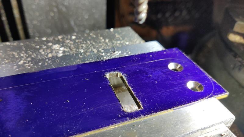
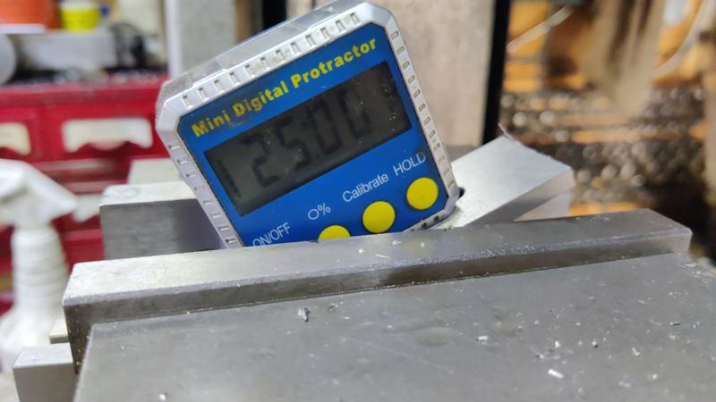
To save grinding time later, I milled a primary bevel on one end. I started by using a digital angle finder thing to set the blade at an angle in the milling vice...

blade_03_setup_for_primary_bevel_800.jpg


...then milled the bevel:

blade_04_milling_bevel_800.jpg


This blade is going to be adjusted in a manner similar to a Norris adjuster, but there isn't really space in a little block plane for that sort of mechanism. Therefore I'm going to use something a bit custom (which almost certainly won't work as well). The blade needs some slots for the adjuster screw to push against. To allow for blade angle adjustment, these slots need to be curved, but the centre of curvature will depend on the position of the blade. That makes it impossible to come up with a "proper" centre (as it'll move when the blade is sharpened).

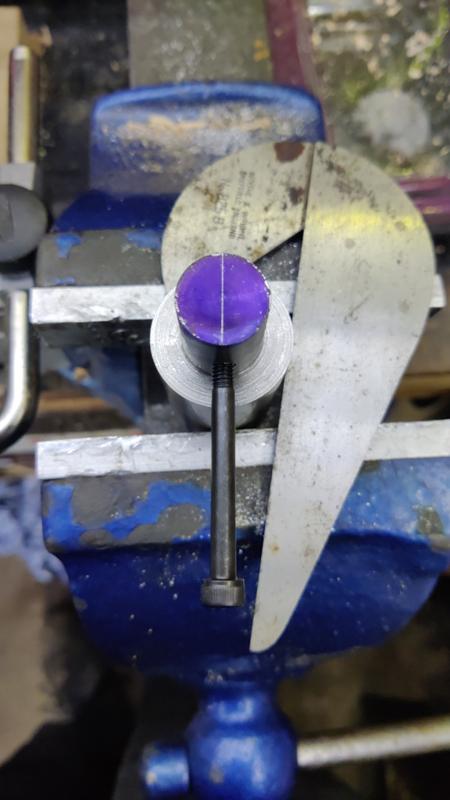
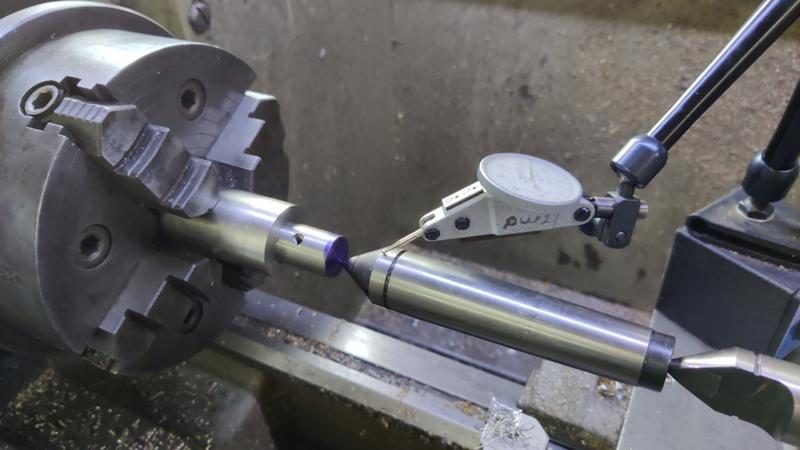
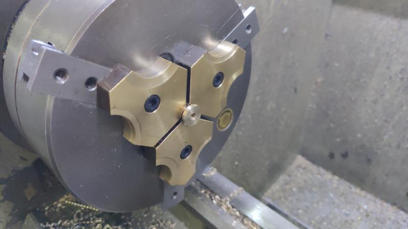
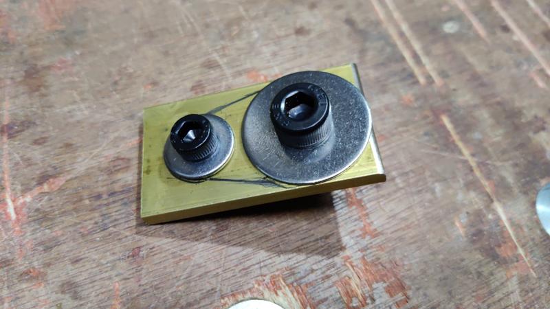
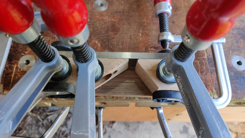
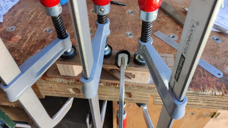
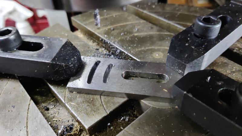
However, in practice, I'll be sharpening the blade with a honing guide and hence the end should stay square with the sides. Therefore, the amount of lateral adjustment needed should be very small and hence a slight mismatch in the centre of curvature of the slot shouldn't matter that much. To that end, I just picked a fairly arbitrary point along the slot and centred that point on the rotary table. I then milled a couple of 4 mm wide slots:

blade_05_milling_curve_800.jpg


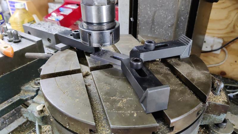
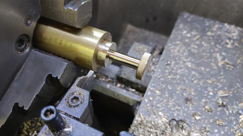
With a 4 mm centre-cutting end mill in the chuck and that end mill sticking out quite a long way (so that the chuck cleared the table clamps), I didn't hold much hope of getting through the cut without breaking the end mill, but I took very light cuts (about 0.1 mm per pass) and took my time and amazingly the end mill survived:

blade_06_milled_curves_800.jpg


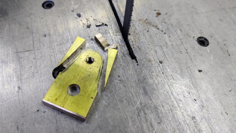
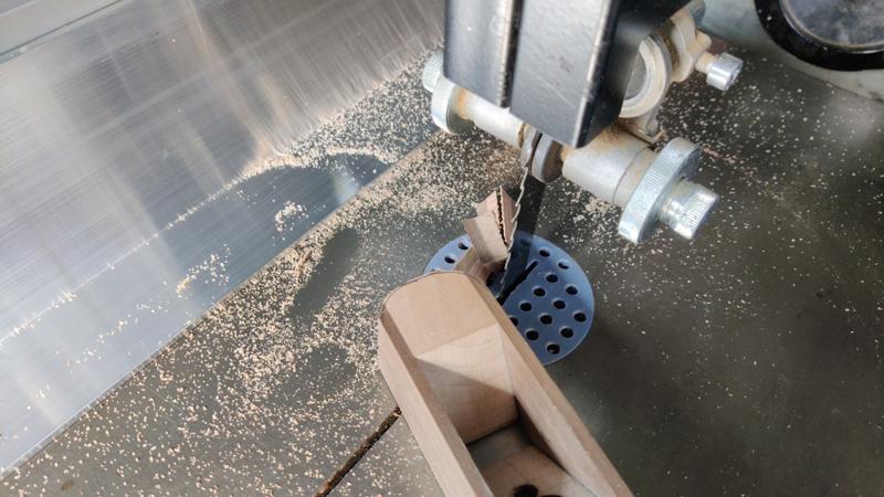
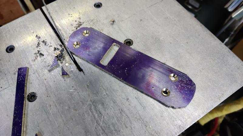
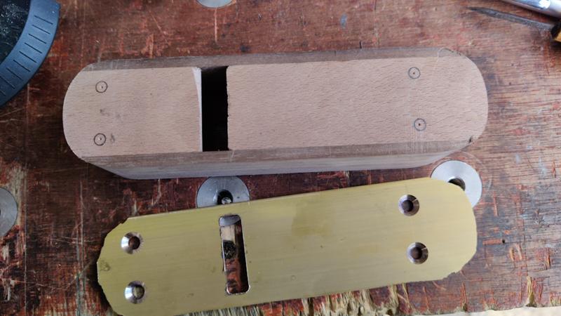
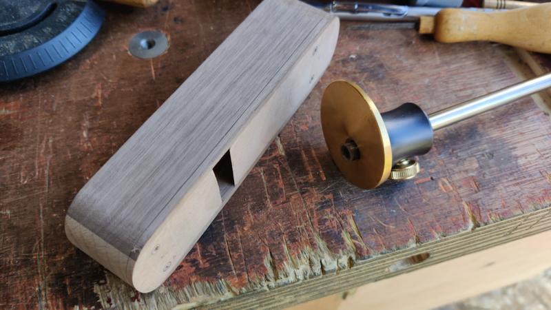
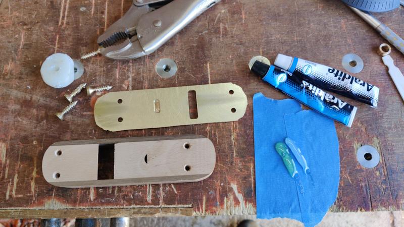
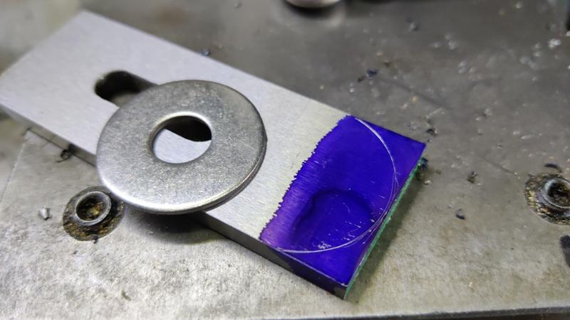
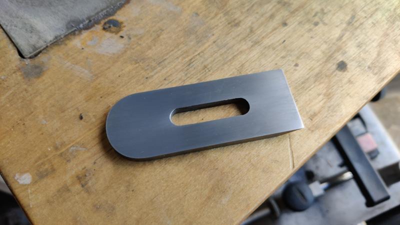
To provide a slightly nicer (and more comfortable in the hand) shape to the rear of the blade, I marked a curve on it using a 30 mm penny washer:

blade_07_marking_rear_curve_800.jpg


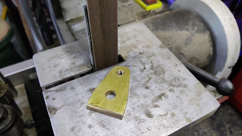
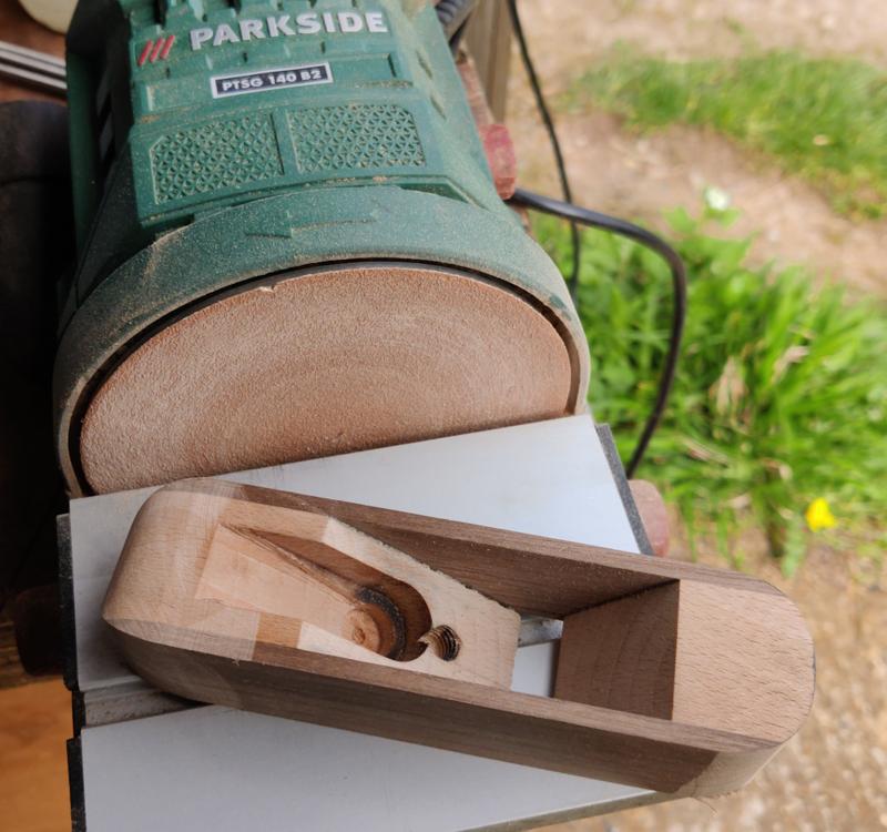
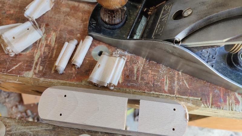
I then roughly hacksawed it to shape and then ground it smooth with a belt sander.

The blade then got wrapped in some soft steel wire:

blade_08_wrapped_in_wire_800.jpg


The wire is there to help keep this stuff in place:

blade_09_boric_acid_800.jpg


That's a mixture of methylated spirits and boric acid. The boric acid reduces the amount of oxidation that happens when heat treating. Heat treating without any sort of protection usually results in lots of black scale forming on the steel, but with the boric acid that effect is minimised. The boric acid forms some tough crystals on the surface of the steel, but they're fairly easy to remove by soaking in boiling water.

With the boric acid coating applied, I placed the blade in a little housing of heat-resistant ceramic wool and applied lots of heat with a MAPP torch:

blade_10_getting_hot_800.jpg


Once it was glowing red and wouldn't stick to a magnet, I plunged it into vegetable oil to quench. After cleaning off the boric acid and lightly sanding it, I then heated it again (more gently this time) and quenched once it was a straw colour at the end:

blade_11_tempered_800.jpg


I then gave the blade a rub-down on some wet-and-dry paper and it was ready for sharpening:

blade_12_sanded_face_800.jpg
 
I really love my Veritas block plane. Super sharp and easy to keep that way. Took me 20 seconds to buy it and required no further effort. This is turning labour to earn cash into tools. You are missing out the cash part Dr Al because it is very clear to me you have missed your vocation, which is to be a tool maker and collector! It's clear btw, that your recent box creation was kust making a home for your new plane ;)

Top skills as ever.
 
Nice work mate, I would use the tap tap methd of adjustment,I made a high angle plane with the Veritas adjuster and their is so much slop it is wery difficut to adjust.

Pete
 
Nice work mate, I would use the tap tap methd of adjustment,I made a high angle plane with the Veritas adjuster and their is so much slop it is wery difficut to adjust.

Pete
Thanks Pete. The tap-tap method is what I use on the other block plane (and also on my metal body Quangsheng one) but I wanted to try something a bit different (and also I wanted to avoid having to take a small hammer in the tool-chest for adjustment - the mallet is a bit big for that). Having just finished this plane (and at the risk of giving spoilers 😉) I can report that it's easy enough to set up.

There is some slop in the adjustment mechanism, but you can feel the backlash easily, so you push it gently up against the backlash limit and then apply a small nudge to shift the blade slightly. It'd probably be more awkward if it needed a lot of adjustment (i.e. if the blade end wasn't square) but it seems okay so far to me. It's definitely not as nice to adjust as a conventional mechanism on a Bailey plane, but it doesn't seem to be much worse than a Norris one. Of course I haven't used it in anger and only time will tell how it goes. Also, there's nothing stopping me using a hammer to adjust it if I do ever have issues with the adjuster.
 
On mine there a cup that holds the adjuster mechanisim that is one source of play, I need to make a new one with a tighter tollerance.
You can just see it in this photo.

Wenge plane parts by Pete Maddex, on Flickr

Assembled

Wenge plane by Pete Maddex, on Flickr

I lives on my CD rack in the living room.

Pete
That's beautiful. Seems a shame that it lives in the living room rather than a workshop though.
 
The next job to work on was the cam that will nudge the blade from side-to-side to provide a bit of lateral adjustment. I started with a bit of 303 stainless steel and turned a section down to 18 mm:

cam_01_stainless_smooth_800.jpg


I then mounted the bar in the milling vice and cross-drilled and tapped the hole M5:

cam_02_cross_tapping_800.jpg


I fitted a cap screw into the tapped hole and used it to help align a centre-finder and scribe a line across the end, parallel with the threaded hole:

cam_03_marking_inline_with_tapped_hole_800.jpg


After marking a centre punch point along that line, I mounted the bar in the four-jaw chuck in the lathe and adjusted it until the centre punch point was on the lathe axis:

cam_04_setting_up_4jaw_chuck_800.jpg


I could then turn an 8 mm diameter cam on the end of the bar:

cam_05_turned_cam_800.jpg


After sawing the bar end off in the bandsaw, I mounted it in a collet chuck and turned the reverse end down:

cam_06_turned_reverse_800.jpg


That end also got a 3.3 mm hole drilled, drilling until I reached the M5 cross-hole. The hole then got tapped M4:

cam_07_tapping_grub_screw_hole_800.jpg


That hole will be used for a grub screw, which will lock a piece of stainless steel M5 threaded rod into the cross-drilled hole.

Finally, I turned a simple brass bush for the cam to rotate in (it should give a smoother action than trying to rotate the cam in a wooden hole).

cam_08_finished_with_brass_bush_800.jpg


Next up is the adjuster, which will be used to move the blade in and out and will also form the "handle" that rotates the cam. I started with a bit of brass bar in the lathe, knurled it at the end and then shaped it:

adjuster_01_shaped_800.jpg


To shape the other end, I used my home-made soft-jaws to hold the adjuster. I could then shape the end and drill and tap a blind M5 hole in the end:

adjuster_02_reversed_shaped_and_tapped_800.jpg


The tapped hole is deep: too deep for most of my M5 taps. However, I have a long-series M5 tap, so I extended the threads deeper using that by hand:

adjuster_03_long_series_tap_800.jpg


This photo shows how the adjuster components fit into the blade slots:

blade_with_adjuster_800.jpg
 
That's a really nifty way of hardening and tempering Al. The wool particularly impressed me; I've always had to hunt for wherever I left the fire bricks last (now permanently gone in a house move). The boric acid marinade is new to me too, kewl!
 
Brass! Shiny, shiny............we like shiny. :)
 
That's a really nifty way of hardening and tempering Al. The wool particularly impressed me; I've always had to hunt for wherever I left the fire bricks last (now permanently gone in a house move). The boric acid marinade is new to me too, kewl!
I've got some fire bricks, but they're the wrong sort (refractory rather than insulating, if I'm getting my terminology right). Therefore, they're great if you want to absorb a lot of heat into the brick, but not so good if you're trying to direct the heat into the part. I'll probably get some insulating fire bricks when I get round to it as the wool gets a bit shabby quite quickly, but the wool does the job for now.

The boric acid trick was one I learnt from one of Clickspring's excellent videos.
 
I think you might be my hero Al, this is so epic!
I'm a chartered engineer (doing electrical design for railways) which makes people assume that I can do things like you have! I can only dream of having skills like you
1714053257673.png
 
I think you might be my hero Al, this is so epic!
I'm a chartered engineer (doing electrical design for railways) which makes people assume that I can do things like you have! I can only dream of having skills like you

Thanks BigMonka, that's very kind of you to say.

I'm a chartered engineer too (doing electronics design in various different manufacturing industries), but all the machining / making I do in the workshop is stuff I've learned in my own time in the workshop over the last 12 years or so (with lots of trial and lots and lots of error!)
 
To make a lever cap, I started with a bit of 5 mm × 30 mm brass flat bar. I drilled two holes, tapped one of them and then used a corner-rounding end mill to round off one end:

lever_cap_01_drilled_and_corner_rounded_800.jpg


I used a couple of washers to mark out the shape of the cap (the bigger washer provided an edge against which to push a ruler for marking a line tangent to the two diameters):

lever_cap_02_washers_for_shape_marking_800.jpg


It got roughed out to shape on the bandsaw, using my home-made vertical saw table:

lever_cap_03_rough_sawn_800.jpg


I then used a little Axminster mini belt sander to sand it to shape:

lever_cap_04_belt_sand_to_shape_800.jpg


The screw for the lever cap is a bit unusual. I wanted a relatively fine thread (as the brass bar is quite thin) so went with M6. However, the slot in the blade is quite long and quite wide (8 mm) and I didn't want the lever cap screw to drop into the slot. To work around that, I made the screw in two parts. The first part looks much like a normal "cheese head" screw, except that there's no slot in the screw head. The second part is a knurled "nut" but with a blind hole. The two parts screw together around the lever cap (they'll probably get glued together in due course), and the "cheese head" provides a bigger contact area on the end of the screw.

The screw components can be seen in the next photo, along with the lever cap which has now had a bit of attention with an angle grinder to make it a bit more shiny (just for @Mike G as he likes shiny brass ;) ):

lever_cap_05_polished_with_screws_800.jpg


The next photo shows how the screw goes into the lever cap, hopefully making it clear how it all fits together:

lever_cap_06_showing_screw_fitted_800.jpg


To hold the lever cap in place, a nut was needed as I'm going to fix a bit of threaded rod into the body (rather than having a screw like you'd find on a Bailey pattern plane). Making the nut was just a case of taking a piece of 303 stainless steel, knurling it, drilling and tapping an M8 through-hole and then chamfering and parting off:

lever_nut_01_shaping_on_lathe_800.jpg


This photo shows all the adjuster and clamp components together:

all_adjuster_components_800.jpg
 
Outstandingly good. Maybe metal work folk would be more used to it, but on a wood forum this is impressive tool making.
 
I wonder if the thread on that adjuster is fine enough. How does it work in practice, Al?
 
I wonder if the thread on that adjuster is fine enough. How does it work in practice, Al?
Seems fine to me, although I haven't used it enough to really know yet: just a couple of test cuts. The M8 stainless bar you can see in the last picture is currently being epoxied into the body. When that's cured tomorrow, I'll be able to test it a bit more.

The thread is 0.8 mm pitch; multiplying by the sine of the bed angle suggests that a full turn of the adjuster lowers the tip by about 0.5 mm. That means that in theory it should be quite easy to move the blade down in 0.1 mm steps (a fifth of a turn), but what it'll be like in practice only time will tell.
 
I'm sure you have control over tolerances, but M6/8 /10 nuts and bolts are incredibly slack, and the amount of backlash they would induce in a plane adjuster doesn't bear thinking about. Do your taps and dies do better than that?
 
I'm sure you have control over tolerances, but M6/8 /10 nuts and bolts are incredibly slack, and the amount of backlash they would induce in a plane adjuster doesn't bear thinking about. Do your taps and dies do better than that?

The stainless steel rod isn't made with my die: it's bought-in threaded rod. Besides, the thread backlash is largely academic: it's swamped by the backlash between the adjuster and the slot in the blade.

I deliberately made the slot a loose-ish fit on the brass adjuster: if I hadn't it would have caused problems with the slot radius uncertainty that comes from moving the blade in and out (a "feature" of my design!).

I don't really see backlash as an issue: my Stanley #4 has loads of backlash (more than a full turn, maybe even two turns), but it's rare I'm repeatedly changing direction so it doesn't really matter - if I've been advancing the blade and want to retract it, I just spin it anticlockwise until I can feel the end of the backlash, then nudge it a bit to move the blade.

I'm curious: are your planes all tighter than that in backlash? Why do you see it as such a problem? I feel like I'm missing something.
 
A thin brass shim glued round the head of the adjuster on Stanley or Record plane reduces the backlash to about half a turn.

Pete
 
....
I'm curious: are your planes all tighter than that in backlash? Why do you see it as such a problem? I feel like I'm missing something.
Not a problem so much as a nuisance. Much of my planing is in oak, and it can vary quite a lot. Some of it can be very fiddly to plane, and nudging the iron in or out a quarter turn or less at a time, taking into account the backlash, can be a more long-winded process than you'd ideally want.

I also have the habit of always winding the adjuster in to take up the backlash, even if I have backed the iron off a bit. It may not be logical, but I persuade myself that I am taking slack out of the system and that everything is more likely to stay where I put it if I've got the adjuster tight against the backlash limit. So that can mean winding all the way out and then all the way in again, to the backlash limit, so less backlash would always be good for me.
 
Last edited:
A thin brass shim glued round the head of the adjuster on Stanley or Record plane reduces the backlash to about half a turn.

Pete
Could you take a photo, Pete. I can't picture how this would help.
 
A thin brass shim glued round the head of the adjuster on Stanley or Record plane reduces the backlash to about half a turn.
I'm pretty sure I've seen something similar with someone on youtube shoving a bit of cardboard over the head of the adjuster for that same reason. It has never felt worth the extra effort (every time you fit the blade) to me.
I also have the habit of always winding the adjusterer in to take up the backlash, even if I have backed the iron off a bit.
I do that too - I work on the assumption that it means that there's something resisting any force trying to push the blade back up.

Perhaps as I get more experience in hand planing it'll start to bug me more!
 
I've just been out to the workshop & taken some rough measurements of backlash (by winding in, marking the wheel with a marker pen & then unwinding until I felt resistance).

Axminster #5: 2.75 turns (not as bad as it sounds as the wheel spins really freely, so you can flick it with your finger a couple of times & it'll spin all the way)

Stanley #7: 1.8 turns
Stanley #5: 1.6 turns
Stanley #4: 1.6 turns
Record #3: 1.25 turns
Stanley #4½: 1.1 turns
Stanley #5½: 0.8 turns
Quangsheng LA Jack: 0.8 turns
Quangsheng LA Block Plane: 0.7 turns
Veritas Bevel-Up Smoothing Plane: 0.2 turns

My new block plane: 0.5 turns - not as low as the Veritas one, but quite respectable I think :)

Oh, and at the risk of spoilers...

20240426_141244.jpg
 
The last major part is the body. I actually started this first, working on the other parts in gaps in the body-making process. I started with a block of beech (left-over from when I made version 4, so already the right dimensions). I marked up the bed angle at 36° with a mouth at an angle 90° to that:

body_01_beech_block_marked_up_800.jpg


I'd intended to do it at 37° but only realised that much later. I don't think the difference of 1° will have the slightest effect on function, I just thought it worth mentioning the discrepancy. 37° was chosen as the equivalent angle of my Quangsheng low-angle jack plane with a 12° bed angle and 25° bevel.

The beech block was chopped up into three pieces, one of which is scrap. My sawing was a little inaccurate and I ended up with a bit of a rounded edge on the bottom of the front piece, but that's no big deal as the bottom face of the body is going to be planed down by about 3 mm later on:

body_02_beech_block_cut_up_note_rounded_edge_800.jpg


I wanted some accurate (in depth, mostly) slots and holes in the body and the most accurate tool for that sort of thing that I have is a milling machine, so I mounted the back piece in the mill vice at a 36° angle, milled the face and drilled and tapped an M8 hole:

body_03_milled_face_and_tapped_800.jpg


I was a bit careless with the end mill (not choosing my travel direction correctly) and there's a bit of tear-out, but it's not the end of the world. I'll consider it a lesson for next time (if there is a next time). The depth accuracy is important as the block plane is quite thin (compared to a bench plane) and I wanted to get the holes as deep as possible (without going all the way through) for strength.

I don't really trust a tapped hole with a relatively fine pitch (1.25 mm) thread in wood, but there isn't space in such a small plane for a threaded insert without it punching through the bottom of the body. When I finally assemble the plane, the threaded rod that goes into that threaded hole will be daubed in epoxy, so the surface area provided by the thread should hopefully give a strong join and I won't be relying on the structural integrity of the threads.

With the tapped hole done, I needed to make the space for the adjuster mechanism. I started by using a 12 mm Forstner bit to make the pocket for the brass bush in which the cam runs:

body_04_forstner_on_mill_800.jpg


A 10 mm end mill was used to open that pocket out to give clearance for the adjuster screw and I then used an 18 mm end mill to make the pocket for the cam body and to open that out into a slot to give the rest of the space of the adjuster. I was a bit slow switching from plunging the end mill to moving the X-axis to cut the slot and that resulted in a bit of burning of the beech. I'll probably try and clean it up a bit later, but it shouldn't cause any problems if I don't:

body_05_end_milling_slots_800.jpg


The sides of the body were made from a bit of American Black Walnut. I planed the sides to give an even thickness, then cut a couple of slices off. I decided to do the glue-up in two stages, firstly gluing the two beech body parts to one side, using a mill parallel as a flat surface to hold the two body bases in line with one another:

body_06_gluing_to_first_side_800.jpg


Once that glue had been left for a few hours, I glued the other side in place:

body_07_gluing_second_side_800.jpg
 
Al, with all this milling of wood to make planes, I think I can see what direction you are going in... But you're going to need a bigger shed! :)

 
Al, with all this milling of wood to make planes, I think I can see what direction you are going in... But you're going to need a bigger shed! :)

It did feel a bit like cheating using the milling machine, I must admit. My justification to myself was that I doubted the plane mechanism would work at all & I wanted to do something fairly quick to prove the concept. That was the same reason for using walnut for the sides, rather than the possibly-teak I used on the last one: I haven't got much of the possibly-teak left so I didn't want to waste it on something that wasn't likely to work.
 
Once all the glue was dry, I turned the straight slot into a tapered one using a 10 mm chisel. This photo sort-of shows a before-and-after shot: I've opened out the one side but not the other:

body_08_opening_out_slot_1_800.jpg


I could have done this on the milling machine at the same time as milling the slot, but I'd have needed to rotate the vice for each side of the slot and it's a lot quicker and easier to just do it by hand. This photo shows the finished slot with the little brass bush fitted into its pocket:

body_09_opening_out_slot_2_with_brass_fitted_800.jpg


The following two photos show the two extremes of movement of the adjuster mechanism.

body_10_one_extreme_800.jpg


body_11_other_extreme_800.jpg


It's not a lot of movement, but it will hopefully provide enough to ensure the blade is aligned properly with the body (as I said before, the blade will be sharpened with a honing guide, so the end should be perfectly square to its sides). The cam can be mounted in either orientation (cam at the top or cam at the bottom). With the cam at the bottom, the effective angular rotation of the blade will be slightly more than it will be with the cam in the position shown in those photos.

The next job was to shape the body a bit more. Firstly, I reduced the thickness of the sides to about 4 mm with a hand plane:

body_12_slimmed_sides_800.jpg


I want some rounded corners on the plane (as I had on the previous versions), so I marked the corner shape with a 30 mm penny washer:

body_13_washer_markup_800.jpg


Shaping it was all done with power, firstly the bandsaw:

body_14_bandsaw_shape_800.jpg


Then my woefully underpowered little disc sander:

body_15_sanding_shape_800.jpg


More shaping will be required once the body is reduced to its final height, but that's a job for later.
 
Despite England having left the Victorian Era a little while ago, it's still quite difficult to buy brass flat bar in metric sizes. The lever cap (which was made from 5 mm × 30 mm brass bar) stock came from China and was an unknown grade of brass, but I wanted the base to be made out of CZ121, to match some other bits of brass I'll be making in the next post. Without being able to buy metric sized bar, I went for some 3.2 mm × 50.8 mm (1/8" by 2") flat bar. I "painted" it in marking blue and, after plonking the body on top, I marked the shape with a scriber:

body_16_marking_on_brass_800.jpg


The marked-up brass bar:

body_17_marked_brass_800.jpg


It was this marking exercise that was the reason for making the wooden part of the body full depth. The slot should match the expected size on the bottom face of the plane. If I had made the wooden body in its final depth, then the slot would have opened up more (due to the angle of the blade-mounting face) and the size of the slot would be harder to gauge.

The brass bar was mounted in the mill vice and four holes drilled and countersunk. A slot was then milled with an 8 mm centre-cutting end mill:

body_18_slotted_and_drilled_brass_800.jpg


A smaller (4 mm) end mill was then used to take a bit more material away in the corners to save filing effort later:

body_19_smaller_mill_for_slotting_800.jpg


The shape was then roughly bandsawed out:

body_20_rough_bandsawing_800.jpg


After cleaning the marking blue off with acetone, the base was placed on top of the body and the hole locations marked for pilot holes to be drilled:

body_21_marked_for_pilot_holes_800.jpg


With the pilot holes drilled, a marking gauge could be used to mark the amount that needed to be removed from the bottom of the body to make space for the brass base:

body_22_marked_for_thickness_reduction_800.jpg


My Stanley #4½ made light work reducing the depth of the body, making some funky shavings in the process:

body_23_stripey_shavings_800.jpg


The planing operation exposed the bottom of the cam hole. I was expecting that: I'd deliberately drilled that hole as deep as I thought I could get away with given the depth of the plane. A small slot will be needed in the brass plate to allow for the end of the cam bush, but that's not a big deal. Sorry for the blurriness of this photo:

body_24_planed_with_hole_showing_blurry_800.jpg


The following photo shows the reduced-thickness body sitting on top of the base. The discrepancy between the two slot sizes is (hopefully) obvious and this shows why I wanted to mark up the brass bar from the full thickness body. The right-hand end of the slot will eventually be filed to match the taper angle of the blade-mounting face of the body:

body_25_showing_slot_needing_filing_800.jpg
 
Coupla things. Firstly, it's dinky, isn't it! It's been hard to picture its size up to now, but then we see it against a 4-1/2.

Secondly, I hadn't followed when you talked about the full depth body previously, but now I can see what you were planning it's obviously a very good approach.

Thirdly (yeah, I know how many things are in a couple! :) ).......are you not worried about brass leaving oxides on the workpiece? I can picture a greeny-grey stain smeared on your next box or drawer. And couldn't it be said that the main advantage of wooden planes is the wood-on-wood slipperiness, and that you're giving that up?
 
Coupla things. Firstly, it's dinky, isn't it! It's been hard to picture its size up to now, but then we see it against a 4-1/2.

Yep, definitely dinky!

Secondly, I hadn't followed when you talked about the full depth body previously, but now I can see what you were planning it's obviously a very good approach.

(y)

Thirdly (yeah, I know how many things are in a couple! :) ).......are you not worried about brass leaving oxides on the workpiece?

Honestly: I hadn't even thought of it. I'll probably worry about it now!

I can picture a greeny-grey stain smeared on your next box or drawer. And couldn't it be said that the main advantage of wooden planes is the wood-on-wood slipperiness, and that you're giving that up?

I don't know whether that's the main advantage, but it's definitely one of them! There were a "Mike G couple" of reasons I went for a brass base:
  1. I'd never tried making a plane with a metal base before & I thought it would be interesting to try.
  2. A wooden base will wear a lot quicker than a metal one. The usual way to deal with wear on a wooden-based plane is to plane the sole. However, this is a shooting board plane that runs in a track, so planing the sole will reduce the thickness and it'll get sloppy in the track.
  3. Brass is pretty & also softer than steel (and hence a lot easier to file/sand to shape).
It'll get waxed regularly (as do all my metal plane soles), so I guess I'll have to hope that the oxidation thing won't cause an issue. Time will tell.
 
I've never made any wood screws before; following this experience, I'm not sure I ever will again! I wanted some custom wood screws to help hold the brass base to the body. I'd like these wood screws to be as invisible as possible, so I don't want a slot of any sort in the screw head. Therefore, I thought I'd have a go at making some custom screws, out of CZ121 brass to match the brass used for the base.

Turning something long and thin is always a bit of a challenge. The way I approached it was to start with a bit of 10 mm brass bar and drill a centre hole in the end. I could then move it out from the chuck and support the end with a tailstock centre and turn a reduced section in the middle:

woodscrew_01_turning_shape_800.jpg


I ground a custom HSS tool to (very roughly) match the profile of a commercial wood screw and then turned a 2 mm pitch thread on the middle section:

woodscrew_02_threading_800.jpg


A chamfering tool was then used to shape the two ends of the threaded section:

woodscrew_03_chamfering_800.jpg


That left me with a two-in-one wood screw...

woodscrew_04_two_in_one_800.jpg


...which I held to the bench vice in a rather unconventional way and hacksawed into two pieces:

woodscrew_05_hacksawing_800.jpg


I then mounted each screw in the soft jaws and turned a point on the end.

woodscrew_06_making_point_800.jpg


That process worked really well for the first pair. The second pair snapped during threading, as did the third pair, so I switched to an alternative process where I made them one at a time. I didn't take any photos, but it was essentially the same as the process above (still with a tailstock support), except that the threaded portion was half the length and the bit on the end providing tailstock support was cut off and binned after threading.

With that done, I had four custom screws to help hold the base in place.

woodscrew_07_four_screws_800.jpg


The screws got waxed, and the inside face of the base was sanded to provide a better glue "key" and then everything was prepared ready for gluing the base to the body:

body_26_sanded_glue_face_and_preparing_to_glue_800.jpg


In that photo you can see the clearance slot that's been milled to allow space for the cam bush poking through the hole in the bottom of the wooden body.
 
So how are you going to turn them into place? Or, are they effectively just locating studs, and you'll turn them in with Mole grips first, glue the sole on, then pein them once the base glue is dry?

Araldite-on-blue-tape is a thing on Youtube. Surely we all have scrap bins, don't we? So why not mix it on a scrap bit of wood (or steel, or whatever)?
 
So how are you going to turn them into place? Or, are they effectively just locating studs, and you'll turn them in with Mole grips first, glue the sole on, then pein them once the base glue is dry?

Yep: turn with mole grips and then pein/peen (apparently both spellings are equally valid - I just checked as I was curious). The screws are there to give a bit of extra strength (as I don't really trust glue for mixed-material adhesion, although it's probably fine).

Araldite-on-blue-tape is a thing on Youtube. Surely we all have scrap bins, don't we? So why not mix it on a scrap bit of wood (or steel, or whatever)?

Dunno really - I've always used masking tape (even before youtube!). I guess in my formative years of using Araldite I didn't have much in the way of a scrap bin (pre-woodwork and when I was mostly working with round metal bar, which doesn't make for a good mixing surface!) so tape seemed a good option.
 
Back
Top