

DaveL
Old Oak
I have a quite old, bought second hand BAS315, which has done some serious work at times, however the last time I was using it the blade broke. On replacing the blade I found that the top guide bearing were no longer parallel with the blade!
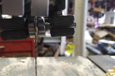
The guides on these saws are a set of die cast metal parts that are held together with M6 bolts. One of these parts should have a 90 degree angle which lines up the lower parts of the assembly with the blade.
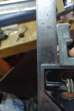
As you can see this had suffered from years of holding the guides up and was no longer close to 90 degrees.
So the hunt was on for a replacement guide part. Most parts for the saw can be bought as spares, however the guide assemblies are not made any more. I did find a complete new guide assembly, both top and bottom guides, completely redesigned, supplied with six new ball bears and give an extra 18mm of cut, the down side, it cost about £75!
I am now the proud owner of a WorkBee CNC machine and while I had only cut mostly wood on it the chaps who sell them posted a video of one cutting aluminium, so the challenge wa on to draw up the part and try to machine it on the CNC. After and number of Google searches I found the top two parts of the guide assembly in the Sketchup 3dwarehouse. This of course opened another can of worm trying to get the drawing into Fusion 360 (the software I use to produce the G code to drive the CNC) in a usable form, I will post about that in the CAD/Sketchup area later. Here is a link to the model.
In the end I figured out how to redraw the required part directly in Fusion 360. The fun then starts producing the tool paths require to machine the part. At this stage I did not have any aluminium, so I cut prototypes from some reclaimed wood in the fire wood pile.
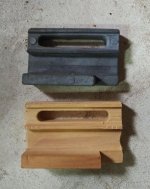
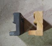
This was one of my first full cut out wooden parts.
On showing this to one of my friends we decided that having a spare internal 90 degree corner was making a stress point and that's probably why the casting had failed. So I went back to the sand and looked at how the assembly fitted together, I could see not good reason why a radius should not be applied to the corner and also no reason why there was the cut out on the lower edge. So I redid the drawing to add these bits in.
I ordered some aluminium from Aluminium Warehouse, I needed some 25 mm thick for another job so decided that I would make the part a bit more chunky than the original. Cutting the Aluminium proved to be much harder than cutting wood.
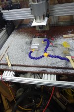
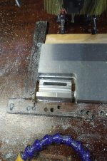
I still don't have a set of feeds and speeds that I can be sure will work, I did break a number of cutters in the process but I now have a new part for the saw.
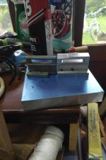
I drilled and tapped the two holes in the bottom of the part by hand.
I needed a pair of longer bolts to hold the thicker guide on, but it all fits and works OK.
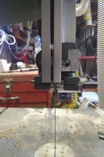
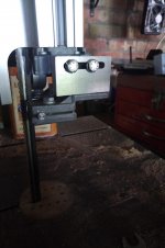
I am quite sure that Bob would have machined one on his mill in a lot less time than I took but I did it with the tools in my shop which is very satisfying.
The guides on these saws are a set of die cast metal parts that are held together with M6 bolts. One of these parts should have a 90 degree angle which lines up the lower parts of the assembly with the blade.
As you can see this had suffered from years of holding the guides up and was no longer close to 90 degrees.
So the hunt was on for a replacement guide part. Most parts for the saw can be bought as spares, however the guide assemblies are not made any more. I did find a complete new guide assembly, both top and bottom guides, completely redesigned, supplied with six new ball bears and give an extra 18mm of cut, the down side, it cost about £75!
I am now the proud owner of a WorkBee CNC machine and while I had only cut mostly wood on it the chaps who sell them posted a video of one cutting aluminium, so the challenge wa on to draw up the part and try to machine it on the CNC. After and number of Google searches I found the top two parts of the guide assembly in the Sketchup 3dwarehouse. This of course opened another can of worm trying to get the drawing into Fusion 360 (the software I use to produce the G code to drive the CNC) in a usable form, I will post about that in the CAD/Sketchup area later. Here is a link to the model.
In the end I figured out how to redraw the required part directly in Fusion 360. The fun then starts producing the tool paths require to machine the part. At this stage I did not have any aluminium, so I cut prototypes from some reclaimed wood in the fire wood pile.
This was one of my first full cut out wooden parts.
On showing this to one of my friends we decided that having a spare internal 90 degree corner was making a stress point and that's probably why the casting had failed. So I went back to the sand and looked at how the assembly fitted together, I could see not good reason why a radius should not be applied to the corner and also no reason why there was the cut out on the lower edge. So I redid the drawing to add these bits in.
I ordered some aluminium from Aluminium Warehouse, I needed some 25 mm thick for another job so decided that I would make the part a bit more chunky than the original. Cutting the Aluminium proved to be much harder than cutting wood.
I still don't have a set of feeds and speeds that I can be sure will work, I did break a number of cutters in the process but I now have a new part for the saw.
I drilled and tapped the two holes in the bottom of the part by hand.
I needed a pair of longer bolts to hold the thicker guide on, but it all fits and works OK.
I am quite sure that Bob would have machined one on his mill in a lot less time than I took but I did it with the tools in my shop which is very satisfying.

