• Hi all and welcome to TheWoodHaven2 brought into the 21st Century, kicking and screaming! We all have Alasdair to thank for the vast bulk of the heavy lifting to get us here, no more so than me because he's taken away a huge burden of responsibility from my shoulders and brought us to this new shiny home, with all your previous content (hopefully) still intact! Please peruse and feed back. There is still plenty to do, like changing the colour scheme, adding the banner graphic, tweaking the odd setting here and there so I have added a new thread in the 'Technical Issues, Bugs and Feature Requests' forum for you to add any issues you find, any missing settings or just anything you'd like to see added/removed from the feature set that Xenforo offers. We will get to everything over the coming weeks so please be patient, but add anything at all to the thread I mention above and we promise to get to them over the next few days/weeks/months. In the meantime, please enjoy!

Kity 619

Pete the Potter

Seedling
Joined
Sep 12, 2026
Messages
6
Reaction score
0
Name
Peter Collett
LOCATION
Gloucestershire
Hi all, does anybody have a photograph of the wiring inside the NVR switch of a Kity 619 table saw. I disconnected mine to replace it and stupidly forgot to take a photograph of wiring layout. Thanks
 
Hi all, does anybody have a photograph of the wiring inside the NVR switch of a Kity 619 table saw. I disconnected mine to replace it and stupidly forgot to take a photograph of wiring layout. Thanks
Unable to help by providing the photo/s you asked, don't have one of those, but did put your question into Google Gemini which came up with a couple of questions of its own before continuing further to try to help. Possibly questions those with a Kity 619 may need to know before getting a photo?

From Gemini:
To assist with wiring your Kity 619 NVR switch, identify whether your machine uses single-phase or three-phase power, as well as the exact type of switch installed.

Is your saw single-phase (230V) or three-phase (380/415V)?
Does your NVR switch have standard numbered terminals (e.g., 1, 2, 3, 4 or 13, 14, 23, 24), or is it a unit with internal ceramic fuses/relay contacts?

Standard Single-Phase NVR Switch Wiring Layout
If you are replacing the factory switch with a standard 4-terminal or 5-terminal NVR switch (such as a KEDU KJD17 / KJD12) on a single-phase (230V) setup:

1
Mains Power Input (Supply Cable)
Prerequisite: Unplug machine
Connect incoming Live (Brown) to Terminal 13 (or 1 / 3 depending on branding). Connect incoming Neutral (Blue) to Terminal 23 (or 3 / 1).
2
Motor Output (To Saw Motor)
Connect outgoing Live (Brown) to Terminal 14 (or 2 / 4). Connect outgoing Neutral (Blue) to Terminal 24 (or 4 / 2).
3
Earth Connections (Safety)
Connect both Earth wires (Green/Yellow) together via the earth post or terminal block inside the switch enclosure. Never route Earth wires through the switch switching contacts.
4
A1 Terminal (If Present)
If your replacement switch has a 5th smaller spade terminal labeled A1 (coil hold-in loop), ensure it is jumpered to the Neutral output terminal.

  • How to verify: Reconnect power, press the green ON button, and release it. The switch magnetic coil should latch and hold the machine running. Pressing the red OFF paddle should immediately stop the saw.
Provide details on the number of terminals on your new switch or share photos of the motor leads to confirm the correct terminal mapping.

Gemini then asked: how do you want to proceed... 2 boxes to select from, 1 for: wiring for 5 pin, 2nd for: wiring for 3 phase.

Is yours 5 pin or 3 phase?
 
Hi it’s single phase
 

Attachments

  • 8789934B-A4A0-431E-B001-5D785168E897.jpeg
    8789934B-A4A0-431E-B001-5D785168E897.jpeg
    234.9 KB · Views: 5
  • IMG_1112.jpeg
    IMG_1112.jpeg
    326.4 KB · Views: 5
  • IMG_1101.jpeg
    IMG_1101.jpeg
    283.6 KB · Views: 5
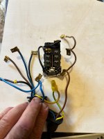
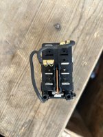
I’m trying to reconnect original switch as photograph
 
More photos of original switch
 

Attachments

  • IMG_1105.jpeg
    IMG_1105.jpeg
    351.9 KB · Views: 3
  • 8789934B-A4A0-431E-B001-5D785168E897.jpeg
    8789934B-A4A0-431E-B001-5D785168E897.jpeg
    234.9 KB · Views: 3
Well, Gemini isn't coming up with photos - possibly not capable? I noticed numbers on the block so hopefully all the following will be of some help. I have to emphasise that I an NOT in anyway saying that this is correct but offering it to try to be as helpful as possible. PLEASE BE VERY CAREFUL. Hopefully it will help refresh how they where before you disconnected

This is the following after telling it single phase (having changed to italics:

On the single-phase Kity 619 table saw, the factory switch setup uses a 5-pin setup (or a standard 4-pin NVR switch if you have bypassed the motor cut-out coil).

The original machine features two separate main rubber cables entering the back of the switch box: one from the mains plug and one leading down to the motor junction box.

Standard 4-Pin / 5-Pin NVR Switch Wiring Layout

Most replacement switches (such as KEDU KJD17, KJD12, or Charnwood HCK3) follow this terminal pin convention:
1
Connect Mains Live (Power In)
Incoming Power Cable
Connect the Brown wire from the incoming mains cable to Terminal 13 (or 1).
2
Connect Mains Neutral (Power In)
Incoming Power Cable
Connect the Blue wire from the incoming mains cable to Terminal 23 (or 3).
3
Connect Motor Live (Power Out)
Cable to Motor
Connect the Brown wire leading to the motor to Terminal 14 (or 2).
4
Connect Motor Neutral (Power Out)
Cable to Motor
Connect the Blue wire leading to the motor to Terminal 24 (or 4).
5
Handle the 5th Coil Lead (If Applicable)
Thermal / Internal Hold Coil
If your old switch or motor harness includes a 5th wire (often Black or a secondary thin wire) for the magnetic coil or thermal reset, connect it to Terminal A1 (the small side tab). If your replacement switch uses a standard 4-pin layout with an internal coil, isolate and cap this extra lead safely.
6
Join the Safety Earth Wires
Chassis Ground
Connect both Green/Yellow earth wires directly to each other using the metal grounding lug or screw inside the plastic enclosure. Do not connect Earth wires to numbered switch terminals.

  • How to verify: Plug in the saw, press the green ON button, and release it. The magnetic switch should latch ON, and the blade will turn. Press the red stop paddle or disconnect the plug to confirm the magnetic latch drops out immediately.
Then it asked about identifying the wire colours:

To trace non-standard wire colors on your Kity 619 harness, you can determine where each wire goes using a basic multimeter on the continuity or resistance setting (\Omega).

Step-by-Step Wire Tracing Procedure
1
Disconnect All Power Sources
Prerequisite
Ensure the main power cable is unplugged from the wall completely before carrying out any continuity tests.
2
Identify incoming Live, Neutral, and Earth
Main Power Cord
Set your multimeter to continuity mode (or lowest resistance).
3
Identify the Run Winding Leads
Motor Harness
Open the terminal box on the motor itself. Touch one multimeter probe to the Live terminal inside the motor terminal block and test the harness wires at the switch end to find the matching conductor (Motor Live / Terminal 14 or 2). Repeat for the Motor Neutral (Terminal 24 or 4).
4
Identify Thermal Overload Wires (If Present)
Thermal Cut-Out
Kity motors frequently feature an internal thermal safety switch (two additional wires, often brown/brown or black/black showing ~0 ohms between them). If using a standard 4-pin replacement NVR switch, these wires can be safely isolated and capped off with terminal blocks (Wago connectors).

  • How to verify: Test continuity across each conductor from origin (plug/motor box) to termination (switch) to ensure zero resistance before connecting to the switch terminals.

To help identify specific wires without a multimeter, list the exact wire colors present on both your power cord and motor harness.
 
Back
Top