Once he's taken the door off and re-hung it in the right place it will open fine, I guess the issue is just that it was stuck open until then.

-
Hi all and welcome to TheWoodHaven2 brought into the 21st Century, kicking and screaming! We all have Alasdair to thank for the vast bulk of the heavy lifting to get us here, no more so than me because he's taken away a huge burden of responsibility from my shoulders and brought us to this new shiny home, with all your previous content (hopefully) still intact! Please peruse and feed back. There is still plenty to do, like changing the colour scheme, adding the banner graphic, tweaking the odd setting here and there so I have added a new thread in the 'Technical Issues, Bugs and Feature Requests' forum for you to add any issues you find, any missing settings or just anything you'd like to see added/removed from the feature set that Xenforo offers. We will get to everything over the coming weeks so please be patient, but add anything at all to the thread I mention above and we promise to get to them over the next few days/weeks/months. In the meantime, please enjoy!
You are using an out of date browser. It may not display this or other websites correctly.
You should upgrade or use an alternative browser.
You should upgrade or use an alternative browser.
Malcolm's Garden Workshop (The Side Doors)
- Thread starter Malc2098
- Start date

Malc2098
Sequoia
The deck is more or less finished. I'll make some steps in due course and i'll tidy up round the bottom.
Next, I'm going to have a go at a post and beam structure to support the roof. Saddle stones already in.

Next, I'm going to have a go at a post and beam structure to support the roof. Saddle stones already in.
MY63
Old Oak
Nice work Malcolm
Looks good mate. You going to paint it the same colour as the shop, stain it, or leave as is?
Malc2098
Sequoia
MY63":3lhvxfd7 said:Nice work Malcolm
Thanks, Michael.
Malc2098
Sequoia
TrimTheKing":qx69bkzq said:Looks good mate. You going to paint it the same colour as the shop, stain it, or leave as is?
Thanks, Mark. Good question! I'm minded to leave it as, but won't make decision till the post and beam roof structure is finished. The timber structure is local douglas fir which looks so nice, (it's stored round the back of the 'shop at the moment) that I'm minded to leave that as it is, sawn. The roof sheathing will be OSB, covered in the same black metal tile effect the 'shop has. So the OSB will be visible inside, along with all the timber and hopefully a few of my joints..
If I were to paint the deck, I think I would not choose a wood stain, but maybe a neutral grey or something like that.
But Mission Control may have other ideas!


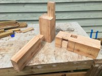

Looks pretty snug to me. Is it necessary for the post to have a through tenon?

- Joined
- Jul 21, 2014
- Messages
- 10,414
- Reaction score
- 165
Andyp":2ho8md99 said:Looks pretty snug to me. Is it necessary for the post to have a through tenon?
Seconded. I think it could be a route in for rain/rot.
Bob
Malc2098
Sequoia
Andyp":i7l8fg3p said:Looks pretty snug to me. Is it necessary for the post to have a through tenon?
Thanks, Andy. It doesn't show up in the photo, but the post/beam m&t is a bit twisted.
I'm not sure about the need for a through tenon, but it was easier to manufacture than the stopped one.

- Joined
- Jul 21, 2014
- Messages
- 10,414
- Reaction score
- 165
I think I'd be looking to chamfer the top faces of the horizontals just a tad to prevent water lying on the surface.
Depending on how much you trim off, the mortice for the uprights might need to be a little shallower than currently.
Bob
Depending on how much you trim off, the mortice for the uprights might need to be a little shallower than currently.
Bob
Malc2098
Sequoia
Thanks, Bob.
This will be the frame for supporting the roof over the decking. The sheathing and tiling will be exactly the same as the main workshop roof. So I do hope the joints will be under cover. However, I will go for stopped M&Ts in the joints. Makes sense. I might not need to chamfer, though. The beams will be taking the rafters.
This will be the frame for supporting the roof over the decking. The sheathing and tiling will be exactly the same as the main workshop roof. So I do hope the joints will be under cover. However, I will go for stopped M&Ts in the joints. Makes sense. I might not need to chamfer, though. The beams will be taking the rafters.
- Joined
- Jul 21, 2014
- Messages
- 10,414
- Reaction score
- 165
Malc2098":1jelao6f said:Thanks, Bob.
This will be the frame for supporting the roof over the decking. The sheathing and tiling will be exactly the same as the main workshop roof. So I do hope the joints will be under cover. However, I will go for stopped M&Ts in the joints. Makes sense. I might not need to chamfer, though. The beams will be taking the rafters.
In that case I agree, no need for chamfer and indeed preferably flat to take the rafters.
Bob
Malc2098
Sequoia
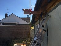
While the sun moved round the workshop, I took the opportunity to establish the distance from foot of Strong-Tie to level with top of workshop plate, so I can mark the length of the post including the joint and the beam onto the story stick.


Rod
Old Oak
That joint looks all wrong to me.
As it will be undercover, take the vertical to the top and mortise the two horizontals in. Mitring the Ends where they meet inside.
Rod
As it will be undercover, take the vertical to the top and mortise the two horizontals in. Mitring the Ends where they meet inside.
Rod
Malc2098
Sequoia
Rod":34q9z9pa said:That joint looks all wrong to me.
As it will be undercover, take the vertical to the top and mortise the two horizontals in. Mitring the Ends where they meet inside.
Rod
I can't agree, Rod. The bottom of the horizontal beam has to be supported by the post, not its tenon. That's why the rafter is set in a little way. That's how the rafter is supported, and the tenon, pegged of course, keeps it there.
From my limited research, the tenon should not be a bearing surface.
Malc2098
Sequoia
It seems I made a rookie mistake in my first attempt. I measured stuff as if the post/beam were perfectly square. As a result, because they weren't square, nothing fitted as well as it could, and the M&T were out of parallel with the beam.
I've tried to read up again, and MikeG would obviously know this bit, but inside each irregular milled beam is a perfectly sized one. So, so long as I have a one face and its edge square to each other, then I only ever measure from those references, and inset those opposite by a small amount. Those references are intended to be the outside of the building. Think that's the idea. I hope it is.
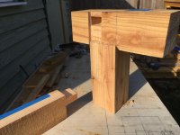
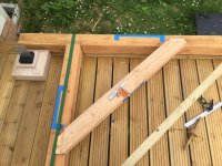
This is the revised drawing I've made. The beam rests on the post and the post's tenon locates it (with pegs eventually). The rafter tie rests on the post and its tenon locates it (with pegs eventually).
BTW, this is from the online version of sketchup.

I've tried to read up again, and MikeG would obviously know this bit, but inside each irregular milled beam is a perfectly sized one. So, so long as I have a one face and its edge square to each other, then I only ever measure from those references, and inset those opposite by a small amount. Those references are intended to be the outside of the building. Think that's the idea. I hope it is.
This is the revised drawing I've made. The beam rests on the post and the post's tenon locates it (with pegs eventually). The rafter tie rests on the post and its tenon locates it (with pegs eventually).
BTW, this is from the online version of sketchup.



Malc2098
Sequoia
Coley":3p7w7gtc said:Malc, this is some first class joinery [emoji106]
Sent from my SM-G960F using Tapatalk
Thanks, Coley, but me and Youtube are on first name terms at the moment. This really is uncharted territory for me.
Malc, I am intrigued.
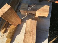
I cut my tenons like this with the tenon edges at right angles to the shoulder.
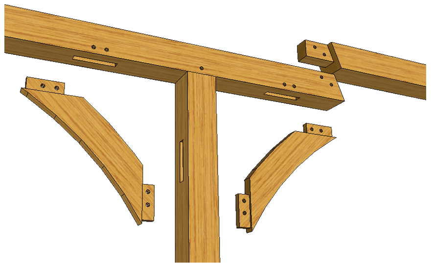
You have cut yours with one edge parallel to the edge of the brace. Why? is this for strength? To get it to fit in the mortice wont they be a big gap?
I cut my tenons like this with the tenon edges at right angles to the shoulder.
You have cut yours with one edge parallel to the edge of the brace. Why? is this for strength? To get it to fit in the mortice wont they be a big gap?
Malc2098
Sequoia
Andy,
I don't know the answer to that. I'm just following framing advice on the net.
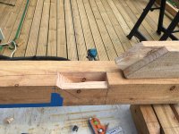
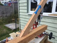
I suspect it's to add strength, because the brace is inset by about 10mm and that L shaped bearing surface you can see in the photo on the end of the brace would need meat behind it to deal with compressive loads or it might fracture the tenon.
The mortise is also cut at an angle and so the tenon fills the mortise.
I've used my little mortise machine to cut the main mortise and then made stepped cuts with it to remove as much as possible before chiselling out the angle.
I don't know the answer to that. I'm just following framing advice on the net.
I suspect it's to add strength, because the brace is inset by about 10mm and that L shaped bearing surface you can see in the photo on the end of the brace would need meat behind it to deal with compressive loads or it might fracture the tenon.
The mortise is also cut at an angle and so the tenon fills the mortise.
I've used my little mortise machine to cut the main mortise and then made stepped cuts with it to remove as much as possible before chiselling out the angle.
Why would there be a gap Andy? The mortice should be cut with an angle to match the tenon, so it's effectively a haunch on the tenon.

Malc2098":1qmqa5za said:Andy,
I don't know the answer to that. I'm just following framing advice on the net.
I suspect it's to add strength, because the brace is inset by about 10mm and that L shaped bearing surface you can see in the photo on the end of the brace would need meat behind it to deal with compressive loads or it might fracture the tenon.
The mortise is also cut at an angle and so the tenon fills the mortise.
I've used my little mortise machine to cut the main mortise and then made stepped cuts with it to remove as much as possible before chiselling out the angle.
Fair enough Malc. Is is the fact that you are cutting a angled mortice that stumped me. A lot of extra work but I can see that it will be worth it.
Malc2098":muulve14 said:This is my first one after the practice. Still need more practice!
View attachment 2View attachment 1
That looks excellent. Dont forget gaps will open up anyway when the wood dries out.
Malc2098
Sequoia
Andyp":39rnrlbt said:Malc2098":39rnrlbt said:This is my first one after the practice. Still need more practice!
View attachment 2View attachment 1
That looks excellent. Dont forget gaps will open up anyway when the wood dries out.
Thanks, Andy. You can tell the weather, I can save it the trouble!


Malc2098
Sequoia
Nowhere near as good as it could be. But I'm new to this.
One bent nearly complete. I've got to cut out the cross tie mortises and cut the posts to length so it matches the height of the existing wall plate.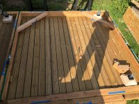
One bent nearly complete. I've got to cut out the cross tie mortises and cut the posts to length so it matches the height of the existing wall plate.
Malc2098
Sequoia
Starting to get the post and beam frame together. I've made four braces and their joints so far.
I've just tried out the ties to check the horizontal framework for square and will incorporate them in trusses at either end. I made up four miniature posts to try them out with. The beams and ties rest exclusively on the top os the posts, and their tenons are only used to locate them. They will be dowelled on Raising day.
I've got two more trusses to make for the far end of the deck. I am hoping the combination of ridge beam, rafters etc connected to the main roof will prevent wracking at the building end. And in any case. I wouldn't be able to open the doors with braces that end.
Not entirely happy with the Simpson Strong Ties. The instructions say a 5mm slot for the blade and 13mm holes for dowels, and everything's a bit loose. I expect the posts to shrink a little, but not that much.
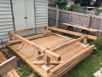

I've just tried out the ties to check the horizontal framework for square and will incorporate them in trusses at either end. I made up four miniature posts to try them out with. The beams and ties rest exclusively on the top os the posts, and their tenons are only used to locate them. They will be dowelled on Raising day.
I've got two more trusses to make for the far end of the deck. I am hoping the combination of ridge beam, rafters etc connected to the main roof will prevent wracking at the building end. And in any case. I wouldn't be able to open the doors with braces that end.
Not entirely happy with the Simpson Strong Ties. The instructions say a 5mm slot for the blade and 13mm holes for dowels, and everything's a bit loose. I expect the posts to shrink a little, but not that much.
MY63
Old Oak
I think it is fantastic Malcolm

Very nice
What is it?
Can you tell I've not been keeping up with the thread?
What is it?
Can you tell I've not been keeping up with the thread?
Robert":x5pgfqzl said:Very nice
What is it?
Can you tell I've not been keeping up with the thread?
Thinking the same thing. I did look back a dozen or so pages hoping to find a plan, without success.
If there is movement in those post supports could you replace one or two of the metal dowels with bolts to pinch up the slot? Or will that spoil the aesthetic?
Malc2098
Sequoia
Malc2098
Sequoia
Robert":37r3kkf8 said:Very nice
What is it?
Can you tell I've not been keeping up with the thread?
Thank you, Robert, but Keep up, please.
Lying on the deck are the two posts and braces for one of the bents. The others are lying down on the other side of the deck. They will hold up the beams and ties at plate level so I can build an intersecting roof into the workshop roof, thus covering the deck.
It's a bit of a timber framing project so I could work more with wood rather than nailing and screwing bits of wood together. It's stretched me, but it's been satisfying.
- Joined
- Jul 21, 2014
- Messages
- 10,414
- Reaction score
- 165
Robert":2ls5jdqb said:Very nice
What is it?
Can you tell I've not been keeping up with the thread?
It's like this Robert. After Malcolm found a way of keeping the workshop door from closing and how much of a nuisance that was, he has now devised a method of keeping the doors closed and is trying that out for convenience as a comparison. :lol: :lol:
Bob
Malc2098
Sequoia
Andyp":20xcq2y3 said:Robert":20xcq2y3 said:Very nice
What is it?
Can you tell I've not been keeping up with the thread?
Thinking the same thing. I did look back a dozen or so pages hoping to find a plan, without success.
If there is movement in those post supports could you replace one or two of the metal dowels with bolts to pinch up the slot? Or will that spoil the aesthetic?
Please seem my reply above to Robert, Andy.
I haven't had any plans as such. I've had to research all the joints and have got drawings of those to help me.
I can make the slots narrower for the blade. I can do them on the bandsaw in the 'shop with a roller stand supporting the other end. But I shall contact Simpson's customer service dept and see if they are supposed to be that sloppy. I shall also measure my 13mm auger to see if it's maybe a bit generous.