• Hi all and welcome to TheWoodHaven2 brought into the 21st Century, kicking and screaming! We all have Alasdair to thank for the vast bulk of the heavy lifting to get us here, no more so than me because he's taken away a huge burden of responsibility from my shoulders and brought us to this new shiny home, with all your previous content (hopefully) still intact! Please peruse and feed back. There is still plenty to do, like changing the colour scheme, adding the banner graphic, tweaking the odd setting here and there so I have added a new thread in the 'Technical Issues, Bugs and Feature Requests' forum for you to add any issues you find, any missing settings or just anything you'd like to see added/removed from the feature set that Xenforo offers. We will get to everything over the coming weeks so please be patient, but add anything at all to the thread I mention above and we promise to get to them over the next few days/weeks/months. In the meantime, please enjoy!

Mike builds a teardrop (Mega update 2)

Phil has valid point Mike.

When we had a caravan in 2017 I had a clip on proprietory canvas cover to protect the front from stones flung up from the rear wheels of the car, an issue dispite fitted mudflaps. keep your eyes open when out driving and you'll see they're very common.

I don't know how much damage would be sustained on glassfibre compared to aluminium but worth considering perhaps if you're interested in keeping it pristine.
 
Last edited:
Yeah, I let an attempt at humour take the place of a sensible answer. I think the sensible thing to say is that most of the lower half of the front of the teardrop is behind the tongue box, which will have a painted canvas finish. I could put a square of perspex over the exposed bottom corners , I suppose......although there is a front marker light there to get around. Or, as you say, I could make up a custom canvas cover held in place by screw-on press studs.
 
Last edited:
It's been a while. To be honest, I've been a bit fed up with this thing, which seems to be taking forever, so I had a few days off.

There are going to be 3 or 4 updates to bring us up to the present. This evenings post is about stuff I did 2 or 3 weeks ago now. I started by tackling the rear hatch........

The rear hatch slides into place on a long continuous hinge (more on that later), and so the wiring for it needs to be take-apart-able. All the driving lights are on the hatch, and one or two other things besides, so there are lots of wires to deal with. Further, it is the only place on the entire teardrop where wires run within the structure. Again, more on that later.

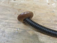
I started by turning a little boss from a scrap of sapele, and working out the necessary hole:

IMG_0505.jpg

IMG_0506.jpg

IMG_0507.jpg

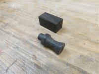
The flexy- ducting in actually a bit of waste water hose left over from the galley sink. Whilst I had a path to the lathe cleared, I turned up a quick prototype knob for the kitchen and bedroom cupboard doors, but it turned out to be too big. Now that I'm a professional turner, these things are pretty easy for me :) .....

IMG_0508.jpg

I hope you get the irony.

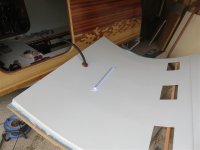
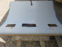
This is the underside of the kitchen hatch, with the ducting in place, the light in place, and some cut outs for the electrical connections:

IMG_0510.jpg

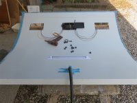
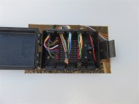
Now all I had to do was wire it:

IMG_0511.jpg

IMG_0512.jpg

IMG_0513.jpg

IMG_0514.jpg

Note the bundle of wires with the black tape around them. They are all spares. If for some reason I have to install raised lights, or a reversing camera, or anything else, this is my only chance of getting any wires into place. One annoyance was that the kitchen light had cables which weren't long enough to reach anywhere where a joint would be accessible. I decided to solder them. Here they are taped up:

IMG_0515.jpg

The cut outs in each corner are obviously behind the driving lights, meaning that if they ever need replacing the wires are accessible:

IMG_0516.jpg

IMG_0518.jpg

I also inserted a couple of draw strings, so if I did ever have to pull more wires into place, at least I'd got a chance. Having finished all that, I could start on the cedar strips:

IMG_0519.jpg

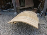
I'm trying to follow the colours of the roof down through the hatch, but as the roof is covered in epoxy it's hard to directly compare my stock with what's on the roof. I graduated my stock from light at one end to dark at the other:

IMG_0520.jpg

.........and just carried on working in from the outsides:

IMG_0521.jpg

IMG_0522.jpg

Time for another batch of epoxy. If you recall, you can either build up epoxy in layers before the previous coat has completely set, or you have to achieve a mechanical bond by sanding to key the surface:

IMG_0523.jpg

IMG_0524.jpg

It's a horrible job.

The kitchen hatch needed fairing:

IMG_0525.jpg
 
That meant belt sander across the grain, then with the grain, then torture boards:

IMG_0526.jpg

Then on a nice dry warm day (ideal for epoxy work), I put 3 or 4 coats on the hatch, and a couple on the teardrop:
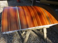
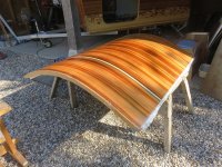
IMG_0527.jpg

IMG_0528.jpg

Unfortunately, the farmer decided that afternoon was a good day to plough up the dusty dry field, and we also suffered a cloud of little insects who decided that drying epoxy was a good place to land. Time to walk away and do something else.....

I had sent a cutting list to a Formica supplier, and went and collected all the various pieces. Contact adhesive has turned into something rare and expensive, for some reason.....but it's the only way to stick Formica down. You may recall that the kitchen worktop was an old hollow core door, for lightness. Well, it was soon to look a bit better:
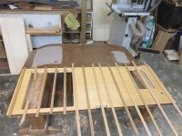
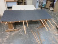
IMG_0529.jpg

IMG_0530.jpg

IMG_0533.jpg

I hate trimming bits! I hate routers.....

IMG_0532.jpg

I'd even taken the precaution of taping up the front edge so as to give myself some peace of mind.

Time to walk away and find something else to do....... :)

I cut away some of the depth of a stainless steel vent, as it was deeper than the tongue box floor was thick. It's to vent the box as it's a gas store:

IMG_0534.jpg

-

It's the easiest thing in the world in Autocad to offset a line and add a radius to the corners. You may recall this drawing from last year:
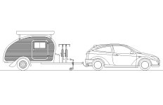
Teardrop side elev.jpgNote the line inside the edge of the teardrop, following it but with rounded bottom corners. That took 10 seconds to draw......and a week to build. Here's the process.

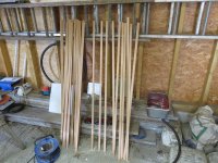
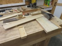
Firstly, a ripped up some 27mm oak boards:

IMG_0535.jpg

Then careful re-sawing on the bandsaw, and planing on the P/T, and I ended up with a whole lot of 8mm thick stock:

IMG_0536.jpg

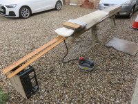
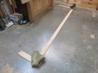
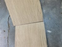
Those boards were about 2.6m long, and I needed a couple of pieces 3.7m long. I wasn't sure whether to do the necessary scarfs before or after steaming them, and decided to do it before. I worked out that I could keep the join out of the steam box. I decided to just do half-lap scarfs. In 8mm thickness, it just seemed to be asking for trouble to try to do a tapered joint:

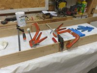
IMG_0537.jpg

IMG_0538.jpg

IMG_0539.jpg

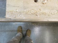
Sorry that's focussed on my shoes......

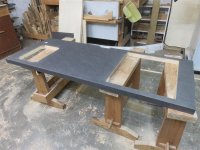
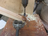
So, I'd got a couple of boards 3.7m long, and a bench around 2m long. I needed a round-over on both edges. I ended up lowering the table of my pillar drill until it could support the end of the boards, then roughing off the waste with a hand-plane, and then making a scratch-stock:

IMG_0540.jpg

IMG_0541.jpg

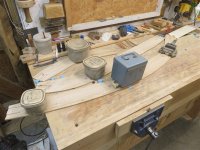
I made up a steam box, and some formwork:

IMG_0543.jpg

IMG_0542.jpg

IMG_0544.jpg

This is what you're up against when steaming. Here's the springback when it came out of clamps the following day:
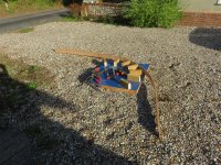
IMG_0545.jpg

Right, that's it for today. More in the next few days.......
 
Last edited:
I can feel the frustration from here... but really, you are making huge progress. I'm sure we are all so relieved that you've got your physical strength back to do this sort of thing, and I'm sure you will soon/eventually have a finished article that you will be rightly proud of.
 
It’s been a while since I did any steaming, but fairly sure the ends were tied together and left for a couple of days.
I think this is to let all the bits of cellulose and lignin settle back and solidify into their new positions.
Probably ok to just re-cook it, it looks as though it might straighten enough to go back in the box?
Ian
Edit, not sure how or just where those bent bits will go on really?
 
They go here, Ian:

IMG_0546.jpg

IMG_0547.jpg

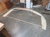
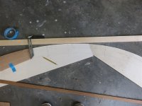
That's the easy bit. Next up comes the side pieces. First, I made a pattern out of ply and hot glue:

IMG_0548.jpg

Note the little blocks so that I could put it back in the same position.

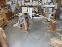
I braced it, because it needed carrying 40 or 50 metres to the workshop, and it's fragile:

IMG_0549.jpg

IMG_0550.jpg

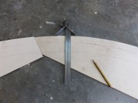
I then spent quite some time on my knees working out where the individual pieces of oak will start and stop. I was going to make up a little jig to give me a right angle to the tangent at any point.......but then I saw this mitre square thingy hanging in the tool cupboard, and it was perfect for the job:

IMG_0551.jpg

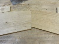
My stock is 8mm thick. I thought about doing a normal half-lap type joint.......but not for long. I decided to do reinforced butt joints. I spent rather a long time sawing and planing:

IMG_0552.jpg

I tried a few methods of extracting the angles from the pattern to transfer them to the oak stock:

IMG_0553.jpg

I had the method completely sussed by the time I came to doing the second side. Anyway, this is what I ended up with:

IMG_0554.jpg

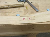
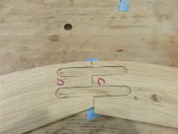
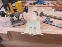
Nine pieces of oak, all with nice tight butt joints. Now I needed to join them together. After a bit of thinking, I made a router jig:

IMG_0555.jpg

This referenced off the outer edge of the frame pieces, which had been shaped to the ply template. This meant that when adjoining pieces were offered up together, the cut-outs aligned:

IMG_0556.jpg

IMG_0557.jpg

I glued these up in pairs, using lots of tape for alignment, and weights to keep everything flat, and to keep the expanding PU glue from pushing the little oak loose tongues out of the joint:

IMG_0558.jpg

IMG_0559.jpg

IMG_0560.jpg

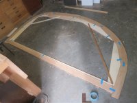
The following day, I dry assembled the whole lot, and kept my fingers crossed that everything would fit perfectly. It was very close:

IMG_0562.jpg

That's a cumulative error of 4 joints. Instead of trying to fix just at that point, I took a shaving off all 4 joints (because I didn't have much to play with in terms of the overall outline, which couldn't end up smaller than the teardrop), and it turned out well:

IMG_0561.jpg

I glued it all up:

IMG_0563.jpg

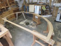
The following day there was still lots of work to do. I put it on horses to bring the outline to its final shape:

IMG_0564.jpg

Note the little protuberances glued onto the inner edge (on the furthest two horses).

I also had the curved pieces in the workshop, to glue on a right angle at the bottom end. Working on them wasn't easy:

IMG_0565.jpg
 
You are getting there Mike. It is looking very good and is going to be the centre of attention where ever you go.
 
Back
Top