• Hi all and welcome to TheWoodHaven2 brought into the 21st Century, kicking and screaming! We all have Alasdair to thank for the vast bulk of the heavy lifting to get us here, no more so than me because he's taken away a huge burden of responsibility from my shoulders and brought us to this new shiny home, with all your previous content (hopefully) still intact! Please peruse and feed back. There is still plenty to do, like changing the colour scheme, adding the banner graphic, tweaking the odd setting here and there so I have added a new thread in the 'Technical Issues, Bugs and Feature Requests' forum for you to add any issues you find, any missing settings or just anything you'd like to see added/removed from the feature set that Xenforo offers. We will get to everything over the coming weeks so please be patient, but add anything at all to the thread I mention above and we promise to get to them over the next few days/weeks/months. In the meantime, please enjoy!

Startrite 165 fettle

Lurker

Old Oak
Joined
Nov 26, 2020
Messages
3,263
Reaction score
595
Location
Loughborough
I have just collected a tidy startrite 165TA table saw :eusa-dance:

I am now embarking on fettling it .
I am going to have lots of questions for the experts/ owners out there.

First off:
How do I lock the saw spindle so I can undo the spindle nut and get the blade off.
I assume that there’s an easy obvious way as a production machine would have a quick change system.
On my cheapo badged TS there’s a flat on the spindle on the other side of the blade.

Edit: have found a hole in the table top that aligns with the rear of the spindle and there is a similar hole in the shaft, if I drop a suitable bolt through the hole, the spindle shaft locks. I knew there had to be an easy way!

Now… elementary thing: I do need to pull the spanner on the spindle nut towards me don’t I??
Standing at the front of the saw facing towards the rear. I am questioning myself as the nut will not budge. I guess it’s not been removed for years.
 
9fingers":1lc3elwi said:
Normally you turn the nut in the direction that the blade turns to undo it. This makes it self locking in use rather than the less convenient self unlocking.

Bob

Thanks Bob,
I was right then, blade turns towards me, so spanner turns toward me.
Stupid thing but you get self doubt when things you expect to happen, don’t.

I think I need to shock it off, rather than risk brut force.
 
Lurker":cnp3i9p2 said:
9fingers":cnp3i9p2 said:
Normally you turn the nut in the direction that the blade turns to undo it. This makes it self locking in use rather than the less convenient self unlocking.

Bob

Thanks Bob,
I was right then, blade turns towards me, so spanner turns toward me.
Stupid thing but you get self doubt when things you expect to happen, don’t.

Try some penetrating fluid on the threads/nut and leave it to do its work for as long as possible rather than a "bigger hammer" or brute force. Plus gas is very good or you can make your own from 50-50 acetone and automatic transmission fluid if you have those products to hand. wd40 is quite poor at penetration by comparison.

Bob
 
Done it!

Managed to get a socket on the nut with a Tommy bar, couple of sharp wacks and it loosened. :D
 
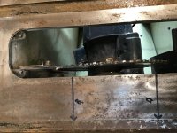
Next problem, the riving knife just fouls a part holding the blade faceplate.
Because the spindle carrier is slightly skewed.

A to B is 120 mm

B is 1.5 mm closer to the table slot than A
So the riving knife is about 3mm too close to the top left adjuster hole.
Note: photo came out 90 degrees wrong, sorry I always make this mistake!!

I assume that there is a way of adjusting the spindle carrier
 

Attachments

  • C33ED1A4-CE92-4294-B30D-F48AE0FB2BBF.jpeg
    C33ED1A4-CE92-4294-B30D-F48AE0FB2BBF.jpeg
    380.3 KB · Views: 4,131
Some saws have the spindle and trunnion mounted in the cabinet and the table top bolts on and can be adjusted or others have the trunnion hung off the underside of the table. These are more of a pain to adjust but jacking up the table on blocks to lift it clear of the cabinet by a few inches normally lets you see what is going on and the bolts to loosen to make the adjustment.

However you achieve it, first get the table slots absolutely parallel to the blade tooth tips and lock that solid.
Shim/fettle the riving knife to be dead central with the blade body.
then get the fence rail 90 degrees to the table slot, finally set up the fence to either be dead parallel to the table slot or slightly toe out away from the blade depending upon how you prefer to work. NEVER have the fence toe in to the blade.

Bob
 
The Riving knife was dead on to the blade, but the way it's fixed is not original.
I have an exploded drawing and I will machine some spacers to take it back closer to spec.

The riving knife is a bodge job so need to make a nice one.
I think I can see how it should look but if anyone has a pattern I'd be grateful.
The same RK is used on the 175 and the three phase versions.
 
I have ordered new drive belts from bearing boys.
Does anyone know how I slacken the pulley distance, to replace them.

There are no adjustable bolt slots on the motor nor spindle assembly as I was expecting.
Does disconnecting the tie bar do the job?

From the drawings I have looked at online many startrite TS are essentially the same design, so I am hoping that someone reading this can help me.

Edit: the motor is mounted on a large eccentric bush, you slacken the bolts and turn the motor. Very clever, easy to get at allowing for precise adjustments.
 
I’ve worked out why the blade isn’t parallel to the slot.

The table top appears to be fixed incorrectly to the body, and hence the spindle carrier mounts.
After a minor medical procedure (eyeball jab) yesterday, I have to take it easy today so will muck around with bolts tomorrow. Can’t quite understand how it all fits properly but I am hoping it will become obvious.
 
For anyone after drive belts and (not surprisingly) bearings, I can heartily recommend bearing boys.
Ordered Sunday evening, postie delivered them at 11am today (Wednesday)
£4.60 for two including p&p.

Drive belts (there are two) are Z24 10x635
 
Not sure if this thread is interesting anyone, but I will carry on incase someone finds it useful in the future.
 
I have solved my misaligned blade vs the table slot.

The table top was held on by 3 bolts! … should be 8.
I think someone removed the top and then when they put it back they dropped it with locating pins in what were actually bolt holes then didn’t see or understand their mistake. As a result the cabinet was distorted.
It was just a matter of replacing the bolts in a proper sequence and everything pulled back into shape.
This also resolved the problem with the riving knife carrier fouling the casting.

Quite enjoyed the problem solving, particularly when everything comes good.

I have decided to bite the bullet and buy a decent riving knife ( the current one is a bodge up in mild steel) £47 delivered is a bit eye watering but I see no option.
 
Pete Maddex":24w3ja2v said:
Didn't Steve Maskery make one from ground flat stock?

Keep up with the posts.

Pete

Agreed - I'm enjoying seeing the progress and chipping in too.

Making RK from ground flat stock is fairly straight forward. The thickness needs to be greater than the body of the saw blade and less than the kerf cut by the blade tips& set on the saw, as GFS is readily available in both metric and imperial thicknesses it is fairly easy to find suitable thickness material.

Bob
 
Definitely carry on pls, so good finding the previous owners c,up on reattaching the top, very heavy and also dangerous to try to move and locate, so easy to see how it happened, but all the bolts left over should have been a bit of a giveaway.
 
Pete Maddex":1suoppqt said:
Didn't Steve Maskery make one from ground flat stock?
Yes he most certainly did. 2 actually, one for standard blades and one for Thin Kerf.

It's easy Jim, just take the cutting slowly so that the steel doesn't distort inthe making. If you are concerned about getting the shape exactly right, and the hole positions, make a dummy from 3mm MDF, or even good cardboard.

S

PS Excellent thread.
 
I have been on holiday in cornwall but back to the saw…..

Ground flat stock is on order.

I thought that I would sort the fence squareness to the table slots, it is out by 3mm front to back.
I had assumed it was a simple job of shimming the rail to top fixings, but after loosening everything up and giving it a wiggle, I have chickened out.
I need confirmation that I am doing the right thing from experts.
 
I shimmed my table rail with some biscuit tin, easy to make sure the non adjustable fence
is parallel with the blade or where you want it, using the slot and an adjustable square.

Not sure how through you want to have this machine.
If doing a real OCD job on it, then you might be concerned about the squareness of the blade when tilted.
I think mine is out by a good bit, and the fence didn't need to be shimmed at all.
You can easily spot with the blade exposed all the way and butting the fence up to it.
Not looked at remedying this yet, but might get around to it someday.

What Kerf is the blade, could it be possible to make one from an old sawblade,
I made one from 3mm stainless, folks were saying their's better materials than gauge plate for the job.
As Steve has said before, best to not have an open ended slot which you can pull out vertically, say if you had the bolts loosened.
you want an elongated hole, in which you cant slot the blade back on/off with loosened bolts.
Yes making it slightly more faff, but you shouldn't need take it off too often.

Oh and beware if it's the same fence as the 275, mine can come loose all of a sudden.
It's obvious that this is a problem on nearly all, should you look at the tensioner screw which gets chewed up.
Mine needs a revamp, as it's not holding up at all now.

Tom
 
Cheers Tom,

I have an old blade and tried drilling it and quickly gave up!!
It might be plan b though.

I was aware that slots were not desirable but thanks for the reminder.
 
I don't think I drilled anything when making mine.
Burned through a cheap round file, and some half used thin discs were handy to have for the tighter radius.

Tom
 
Ah!
I was thinking that I would need to drill a load of holes to join up into a slot.

If the ground flat doesn’t materialise (someone is going to see if they have some), then I will try that.
Good point about the discs, I have a box full of thin cutting discs for my 4” angle grinder.
 
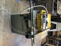
It dawned on me yesterday that I had not checked the TS for electrical safety so I got the tester out of the loft.

All good.
 

Attachments

  • EADCAAA5-A6CC-4C62-9944-ADED8228A64D.jpeg
    EADCAAA5-A6CC-4C62-9944-ADED8228A64D.jpeg
    292.3 KB · Views: 3,531
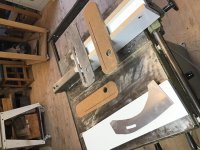
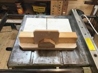
Started to make a couple of zero clearance insert plates.
Have made a riving knife out of some ally, I know it’s no good long term but I am using it to finesse my final shape and for short term use. It also helped me get the spacers that I made spot on.
 

Attachments

  • 4529B17A-3840-4990-9159-3A2290A268AA.jpeg
    4529B17A-3840-4990-9159-3A2290A268AA.jpeg
    337.4 KB · Views: 2,766
That's quite a large hole in the insert, has there need for it to be so large?
The ones on my throat plate are also matched to the aluminium one but are about perfect
finger catching size, or maybe a bit larger, (but that's how these things happen I suppose :lol: )
I'd definitely make a second hole as they might get very tight.
Your saw seems the same as the 275 in size, I thought it was going to be one with a smaller footprint.
Guessing the motor is a wee bit smaller and is the only difference...
Does it take a 12" blade.. and still retract into the cabinet?

Only had to use my saw yesterday, and noticed the riving knife could lift up a couple of mill.
As in rotate?
It still followed the curve of the blade nicely, and still very solid.
Couldn't get the bloomin insert out to check it out to check.
Yet another thing to sort out on my machine.

Watching with interest
Tidy job on the template.
 
Cheers chaps,

Just been to a local fasteners company for bolts to sort the fence bars.
Cost me £1 for ten :D

I think some people have fitted a 250mm blade but I have decided to stick with 235mm.
I made two throat plates and will treat them as consumables.

The aluminium RN has been a useful experiment, but I now have some GFS to do a decent job.
I have three blade guards and I am considering which one is best.
Made a sledge yesterday and also a short fence, not as nice as Steve’s but good enough for now.

Visitors today so will report back when I have had a fiddle with the fence bars.
Next job is some castors as my workshop is not big enough to have the TS in a fixed position.

Thanks for the feedback.
 
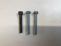
Bolts for the bars, I could not get quite the right bolts,but once they are fixed they will not need to be moved again.
The original black one has a hex but isn’t a metric size, I have lots of similar metric ones but none are quite long enough. The fastener company didn’t have any either.
So I got some pozi cheese head and turned a bit off the head to fit.

Edit: I started to swap these out, but I have now realise the nut and bolts that I am replacing aren’t the original fixing method. The cap screw fixing the bars should screw into a thread tapped into the table, there should not be a nut and the bolts I have are undersized.

I will try to ascertain the cap screw thread size*, but for now I have carried on and I think the shimming has resolved the out of square fence.

*it’s between M6 and m8, does anyone know what would have been the original?
 

Attachments

  • 71045D8D-B45A-4D38-894A-E061B3364249.jpeg
    71045D8D-B45A-4D38-894A-E061B3364249.jpeg
    296.5 KB · Views: 2,700
Pete Maddex":3csutrme said:
Do you have enough meat around the holes to drill and retap?

Pete

Problem is that a m8 will not pass through the hole in the bar.
I used M6 which has clearance for both holes

I don’t think it’s an enormous problem, but it would be nice to get right.


The steel that was given to me for the riving knife turned out to be too thin, so I reverted to plan b which was to use an old 250mm saw blade from my other TS. Worked out quite well.

I now have everything good enough to safely use the Startrite, so I will try to sell on the old TS, will see what happens when I post it on Facebook market place.
 
The strange thing is that the most likely bolt size for an older UK machine would be 5/16 and that is so close to 8mm that a clearance hold designed for 5/16 would normally pass an 8mm bolt through.

It is hardly credible that a 9/32 bolt would have been used as they would have been specials back in the day and nigh on unobtainable today.
7mm is often found on cars but rarely elsewhere which leaves 1/4 or 6mm and they are a bit weedy for the job

Easiest thing to me would be to open up the holes to 8mm and re-tap the female thread to M8 (tapping drill 6.8mm)

Bob
 
If I remember rightly Startrite actually used BA threads on some of their saws in the fence, though a can’t remember exactly what for, have you tried a 0BA cap head? As Bob said probably a bit weedy anyway, 5/16” BSW might be more likely.
 
Ah! BA thread pitch is 0.9mm raised to the power of the BA number. Yes British Association threads are metric!!
So 0BA comes out at 1mm pitch so M6 will fit after a fashion although the pitch angle will be wrong 47.5 deg vs 60 for metric. run in a m6 tap will sort that out with ease.

Bob
 
9fingers":bcrlviit said:
Ah! BA thread pitch is 0.9mm raised to the power of the BA number. Yes British Association threads are metric!!
So 0BA comes out at 1mm pitch so M6 will fit after a fashion although the pitch angle will be wrong 47.5 deg vs 60 for metric. run in a m6 tap will sort that out with ease.

Bob

Can’t be that then, as an M6 passes through the threaded bit in the table with clearance to spare.
 
Trevanion":1jg33kar said:
If I remember rightly Startrite actually used BA threads on some of their saws in the fence, though a can’t remember exactly what for, have you tried a 0BA cap head? As Bob said probably a bit weedy anyway, 5/16” BSW might be more likely.

I have some BSW taps so I will have a look.

Edit: 1/4" BSW passes through both holes.
5/16 BSW is too big for the bar hole.
 
Lurker":2cgwgfvy said:
9fingers":2cgwgfvy said:
Ah! BA thread pitch is 0.9mm raised to the power of the BA number. Yes British Association threads are metric!!
So 0BA comes out at 1mm pitch so M6 will fit after a fashion although the pitch angle will be wrong 47.5 deg vs 60 for metric. run in a m6 tap will sort that out with ease.

Bob

Can’t be that then, as an M6 passes through the threaded bit in the table with clearance to spare.

Ok get a bit of dowel that will just fit the clearance hole paring down if needed. Chamfer the end and grease the first inch. Thread that into the tapped hole to form a male version of the thread. Remove and measure the id and pitch to be certain what the thread is.
Bob
 
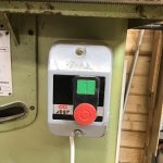
I think I have taken this as far as I am going to, but I would like the off button to be more sensitive.
On my old TS I made a Steve Maskery inspired kick plate, but can’t see how to do this on the startrite.
I have seen some professional machines with an auxiliary stop button at floor level, anyone fitted one?

The on/ off box looks like a recent ish addition, does anyone have experience of these?
I thought that I would ask before I start rootling in it’s innards.
Or can anyone recommend a replacement?
 

Attachments

  • 9D41DA16-8F71-4DCE-964A-B4B77E10DDB6.jpeg
    9D41DA16-8F71-4DCE-964A-B4B77E10DDB6.jpeg
    206.1 KB · Views: 2,482
Back
Top