• Hi all and welcome to TheWoodHaven2 brought into the 21st Century, kicking and screaming! We all have Alasdair to thank for the vast bulk of the heavy lifting to get us here, no more so than me because he's taken away a huge burden of responsibility from my shoulders and brought us to this new shiny home, with all your previous content (hopefully) still intact! Please peruse and feed back. There is still plenty to do, like changing the colour scheme, adding the banner graphic, tweaking the odd setting here and there so I have added a new thread in the 'Technical Issues, Bugs and Feature Requests' forum for you to add any issues you find, any missing settings or just anything you'd like to see added/removed from the feature set that Xenforo offers. We will get to everything over the coming weeks so please be patient, but add anything at all to the thread I mention above and we promise to get to them over the next few days/weeks/months. In the meantime, please enjoy!

Electric Motor Problem, 2nd new motor rec’d, and resistance tests

I think it most unlikely that the new motor has a bent shaft, there is no sign of such when running free of the cutting disc.

Motors designed for shredders are usually very robust with heavy rotors to provide maximum mechanical inertia when presented with the shock loading of brash input.

I'm intrigued by your observation that the fan on the new motor spins independently of the rotor shaft. can you see why this is so?
 
I’m at loss to understand too Chas. I explained the situation to the supplier as I did here and showed them the videos. They are happy to replace the motor so when it arrives we will see. If it does not solve the problem then I will get a multimeter and measure the capacitance of the capacitor.
I would like to understand if a capacitor can perform differently if the motor is under load or not? Thoughts anyone?
 
If you do get a multimeter measure the resistance of each coil (the mains connections is one coil, capacitor connections the other.). Both will be a low number of ohms but the mains should be higher than the cap. It would be interesting to compare faulty new unit to replacement when it arrives. I'm still suspicious about the coil connections being reversed.

A capacitor either works or it doesn't. Too much voltage will damage it and to a degree it will self heal that damage but can of course fail completely. Capacitors are 2 conducting sheets with an insulator between them. 2 x A4 sheets of kitchen foil separated by cling film in between makes a capacitor of very low value but a capacitor it is. Self healing is if a bit of it shorts out then blows away the short like a fuse so there is no more short.
 
Ok Robert happy to give that a try. I've ordered a multimeter so with a little more help (exactly what to measure, how and where) as I have never used a multimeter before). I should be able do those measurements over the weekend.

Just for interest and for Chas here are a couple of vids showing the fan spinning with the shaft on the old motor and the fan spinning without the shaft moving on the new motor. The fan does spin when the new motor is running.

new motor

old motor
 
Just for interest and for Chas here are a couple of vids showing the fan spinning with the shaft on the old motor and the fan spinning without the shaft moving on the new motor. The fan does spin when the new motor is running.

Will be interesting to see if Replacement Motor Fan is free to rotate and not connected directly to Rotor shaft.

Has by any chance the free spinning fan come loose due to a fixing bolt unscrewing?

If a single phase motor is designed to have a capacitor fed winding to assist starting/running the winding also determines the direction of rotation.
If starting, which it may well do, without the capacitor feed without any shaft load there is a 50/50 chance it will spin in the opposite direction, this could cause a bolt in the end of the shaft securing the fan to come loose. (bolt may be left hand thread)
 
Last edited:
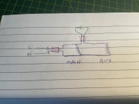
On the electrical side, if the circuit is as below, which is likely, you could conceivably measure each winding separately.

The two white plugs are shown here in red:

image.jpg

Unplug the cap and mains connections.

Main: measure between L and N.
Aux: find the cap connection that’s a dead short to one of the mains (left-hand one to ‘L’ here). Measure between the other cap connection and the other mains connection (right-hand one to ‘N’ here).

EDIT: while you wait for the meter, you could try unplugging the cap and very briefly switching on, to see if it behaves the same. If it does, that would suggest the aux winding or cap is at fault.
 
Last edited:
Disconnected the cap, switched in, motor hums but does not turn.

No indication of a loose bolt holding fan on the shaft.

Using a multimeter must be second nature to you chaps, to me the symbols and terminology are like a foreign language. What I learnt at secondary school about ohms, volts, amps, watts, capacitance etc was forgotten by the time I took my O levels.
I may need more help of exactly how to use a multimeter and exactly what needs to be tested, disconnected before testinng, switched on or off etc.
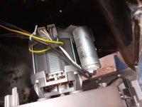
Here is an image of the wiring at the moment which is exactly how it was with the original motor.
20250522_174701_resized.jpeg

Multimeter due tomorrow, delivery is usually late in the day.
I’ve a lot on at the moment, funeral in UK next week and emptying of daughters uni flat. I doubt the new motor will arrive before I leave so maybe a couple of weeks before I can get back to this.

Again thanks for all the help. I am sure that the collective knowledge here will get this sorted even if there is a numbskull at the controls.
 
Disconnected the cap, switched in, motor hums but does not turn.
As expected for an electrically healthy motor, then. It’s a basic test so doesn’t rule out electrical problems, but does tend to point us to a mechanical issue.
 
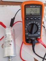
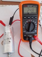
Cap test results. As that is within 5% of 25 can we assume all is good?
20250523_162348_resized.jpeg

With specific reference to the image in post #48 is it worth me testing anything else? Someone is going to have to tell me. Which meter setting, which multimeter lead goes where on the meter and on the connections?
Of shall we just wait until the new motor to arrive which is currently with DHL in Germany?
 
Cap is good.

Hook in the standard probes, if you have them, the same way you’ve done the crocs, and set to this one:
IMG_1323.jpeg

With both motor plugs unplugged:

1. Short the meter probes together and note the reading.

2. Measure between the two mains terminals of the motor.

3. Measure between the two capacitor terminals.

* 2-1 is the main winding resistance.
* 3-2-1 is the aux winding resistance.

4. Measure between each of the four terminals and the metal body of the motor, just for completeness.
 
Last edited:
Cap is good.

Hook in the standard probes, if you have them, the same way you’ve done the crocs, and set to this one:
View attachment 33658

With both motor plugs unplugged:

1. Short the meter probes together and note the reading. 0.4

2. Measure between the two mains terminals of the motor. 2.4

3. Measure between the two capacitor terminals. 9.0

* 2-1 is the main winding resistance. 2.0
* 3-2-1 is the aux winding resistance. 6.2

4. Measure between each of the four terminals and the metal body of the motor, just for completeness. 0

Measurements done as above. What does it all mean?
 
Trying to keep it not too technical.. Your meter uses its internal battery to send a small amount of DC electricity into whatever you connect the probes to. How much goes through is measured in Ohms. Even copper wire resists the current a little so it will have a resistance value that is a low number of ohms or even a fraction of 1 ohm. That's why you short the probes first - to see the resistance in the meter leads. The numbers from the motor will give an idea of how much wire there is on each pair of connections and from that we can see which coil is which..probably :)

Just fyi... If a battery puts out 1 volt and is connected to a 1 ohm resistor then 1 amp will flow through the wire. The resistor will heat up and will put out 1 V x 1A of power... 1 watt. That all works for DC. AC when coils and capacitors are involved is more complicated as the volts and amps are not happening at the same time called out of phase. For resistive only loads like an electric fire the amps volts and watts work out just like for the DC battery.
 
Thank you Robert for your patience and explanation.
My next question is what is normal? Are the measurements I recorded what you would expect from the motor?
 
Well the customer service from www.Motoruf.de has been excellent. New motor just received.
So I will fit later today I hope and let you all now the outcome.
Is there anything else worth checking before I fit the new motor?

I thought that I should test the resistance on all the motors. Here are the results.

Resistance testing Viking shredder motors
Original burnt out motorfirst replacement motor2nd replacement motor
Meter short1.40.41.4
Motor connectors3.82.43.4
Cap cannectors7.89.09.8
These figures seem reasonably consistent but I have no idea what I should expect.

On the 2nd replacement motor the shaft spins when I turn the fan.
 
I didn't expand your quote reply so didn't see the numbers until now.

I took ONC electrical engineering and HNC electronics back in the 70's. We covered induction motors on the ONC but it hasn't been part of my working life so no claim to expertise just memories and a general electrical understanding.

I expected a higher resistance for the mains connected winding than on the capacitor connected winding but that doesn't seem to be the case. The capacitor terminals have both coils in series with no mains connected so that is the total - about 8 ohms. The mains connected winding is 2 ohms so the starting winding is 6 ohms. maybe the start winding is thinner wire or something. Anyway my lack of motor knowledge is clear.

The similarity in figures between the 2 new motors shows the wiring is the same and if there is a fault it is probably mechanical. There could well be a brake unit inside the motor or fan hub that is the problem.

Your burnt out motor figures imply it was the capacitor connected coil that failed as the mains connection are 2.4 ohm similar to the new motors. Can you test the old capacitor?
 
Due to the extra length of the new cap I had to cut the wires on the old cap very close. Holding the meter's probes as best I could on the wires there was no reading on the meter.

IMG_4162.jpg
 
These figures seem reasonably consistent but I have no idea what I should expect.

Reasonably consistent is about all we’re looking for. Nothing grossly abnormal except for the old aux winding. I would question your 0.4 ohm meter short reading, and be tempted to measure again, but probably not worth it.

Due to the extra length of the new cap I had to cut the wires on the old cap very close. Holding the meter's probes as best I could on the wires there was no reading on the meter.

View attachment 33664

In the picture, you have the meter on ohms, not capacitance. Click it one to the right and try again.

I expected a higher resistance for the mains connected winding than on the capacitor connected winding but that doesn't seem to be the case.
We’re down in the depths of induction motor design, which isn’t my area, but it could make sense if you consider the impedance of each winding.

Z = R + jX so by increasing R, you’re lowering the impedance angle. This will shift the current phasor earlier, adding to the leading effect from the capacitor, giving a bit more phase shift to the aux winding.

If you think back to split-phase motors, that’s how they make the start winding lead the run one, by having a higher resistance in the former. No capacitor needed.
 
Last edited:
Actual capacitance 21.5 which is still within the 5%
I make the minimum 23.75 uF, so it is under, but still, not grossly out of whack.

As far as I can see, the low value would reduce aux winding current, and overall torque, making the motor ‘work harder’. It may be the main winding that burnt out as a result, because the aux one was no longer pulling its weight. Or… both windings were getting hot, stressing the insulation, and the aux winding let go (shorted -> overheated) first, which is more consistent with the halved resistance reading of 2.6 ohm, versus 6.2 or 5.0 in the new motors.

The only thing we’re missing are the readings between all four terminals and the motor body, for each motor. Ideally, all ‘0L’ - anything else would likely have tripped your RCD. [Edit: I see they’re added to the quote as ‘0’. I assume this means ‘0L’, in which case, all ok.]
 
Last edited:
Success . 2nd replacement motor fitted, tested under load for 20 mins, two sackfuls of shreddings passed through, switched on and off half a dozen times, runs sweet as a nut. I'd do more but started to rain here.

My, not so expert, hypothesis of what has happened:-
Original motor burnt out, old age and possible failing capacitor.
First replacement motor was faulty/damaged on receipt, remember the shaft does not spin when the fan is turned. I can't explain why it worked for 5 mins although I can assume the fault just got worse until it failed completely.
Second replacement motor does not stop with a thud like the first one did, another indication that the first replacment was faulty.

To everyone that commented on this thread I thank you. Just knowing that there are people around here that can help when things do not work gives people like me the confidence to have a go, safe in the knowledge that help can be found from a trusted and reliable source.

Not much use to anyone outside the EU but the customer service of www.Motoruf.de has been excellent. Advised them of the problem on Weds at 10.30am; new motor received at 10.00am Saturday.

Now what can I do with two electrical motors? There must a a bob or two's worth of copper in them.
 
Last edited:
Now what can I do with two electrical motors? There must a a bob or two's worth of copper in them.
Do they not want the first new motor back?

If not, maybe strip it down on a rainy evening to see what happened. Otherwise, with various destructive tools, you can chop out the windings - makes a few quid more than a whole motor.
 
Do they not want the first new motor back?

If not, maybe strip it down on a rainy evening to see what happened. Otherwise, with various destructive tools, you can chop out the windings - makes a few quid more than a whole motor.
Nope, told me I could keep it, replaced under warranty. I expect you can imagine it is quite heavy, probably cost more in shipping costs than it is worth.

We’ve a load of scrap metal odds and sods from my father’s place to take to scrap metal dealer. I’ve never stripped a motor down before so I may well do so.
 
I've been out all day. Good news with the new motor. This thread has reminded me how much I don't know :)
 
Well done for your perseverance, I doubt I would have bothered and I normally enjoy fixing stuff.
 
Back
Top