• Hi all and welcome to TheWoodHaven2 brought into the 21st Century, kicking and screaming! We all have Alasdair to thank for the vast bulk of the heavy lifting to get us here, no more so than me because he's taken away a huge burden of responsibility from my shoulders and brought us to this new shiny home, with all your previous content (hopefully) still intact! Please peruse and feed back. There is still plenty to do, like changing the colour scheme, adding the banner graphic, tweaking the odd setting here and there so I have added a new thread in the 'Technical Issues, Bugs and Feature Requests' forum for you to add any issues you find, any missing settings or just anything you'd like to see added/removed from the feature set that Xenforo offers. We will get to everything over the coming weeks so please be patient, but add anything at all to the thread I mention above and we promise to get to them over the next few days/weeks/months. In the meantime, please enjoy!

Like the ocean under the moon

Dr.Al

Old Oak
Joined
Dec 31, 2020
Messages
3,505
Reaction score
2,104
Location
Dursley, Gloucestershire
Name
Al
This is a project I've wanted to have a go at for a while. I think there's a fairly high chance it'll end up going through several iterations as I discover all the design problems but I think the journey will be interesting nevertheless.

I'm going to make myself a bench plane. I don't really need any more planes (although my collection is tiny compared to @AndyT's), especially not bench planes, but I like making tools and I find it really satisfying to be able to use tools I've made on other projects. The plan is for it to be somewhere in between a #4 and #4½ in size (probably the length of a #4½ but a width closer to that of a #4). Part of the reason for choosing that width is simply the material I've got at the moment but regardless I'm aiming for a relatively small plane.

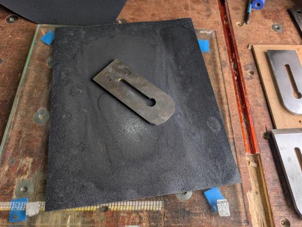
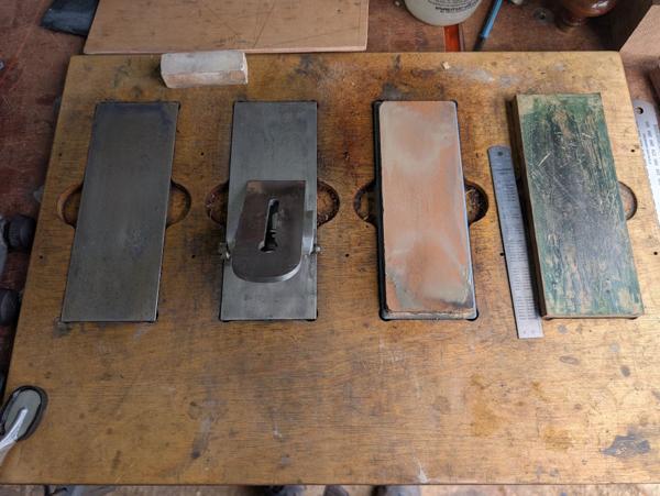
I had a rummage around and these looked like the best bits of material I had:

2026-03-27-01-materials-to-start-with_600.jpg


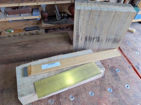
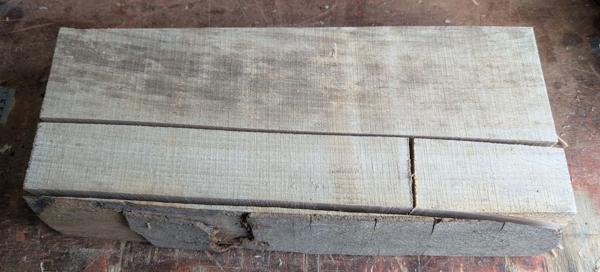
That big bit of beech to the right is really badly cracked, ruling it out sadly. I had thought (after only looking on one side) that there would be enough to take a slice out of it and use that, but on closer inspection I realised that it wasn't going to be much use for anything other than firewood. The darker wood at the back was something I picked up in an antique shop, sold as a mahogany lintel. That's a definite option and I'll almost certainly use it for the plane's handle, but the initial plan is to use the other piece of beech for the body (with a brass base giving it extra strength). This gives an idea of the sizes of the main bits of material:

2026-03-27-02-beech-dimension_600.jpg


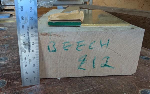
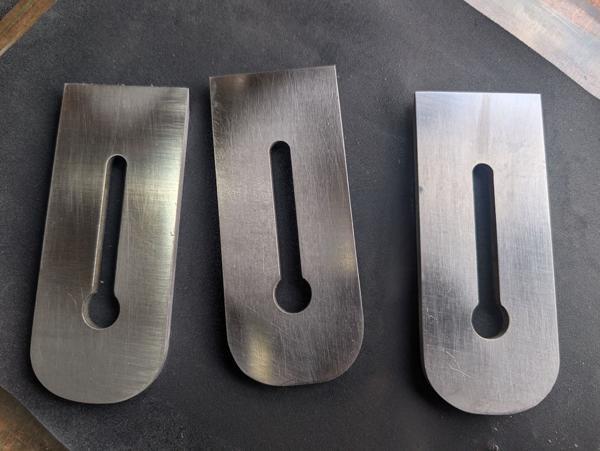
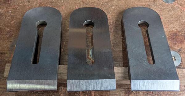
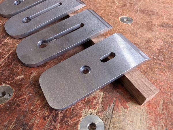
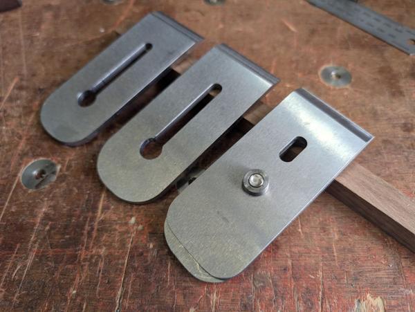
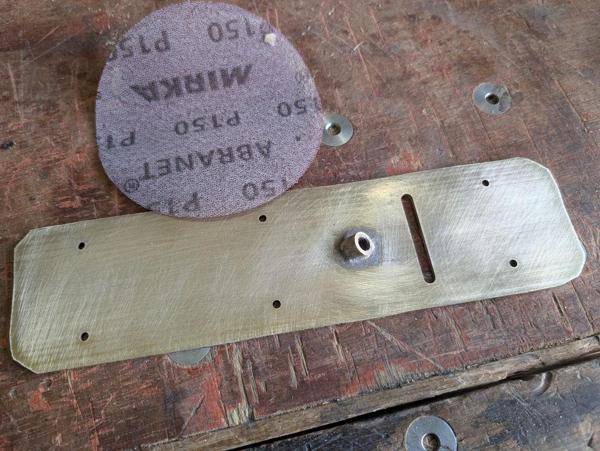
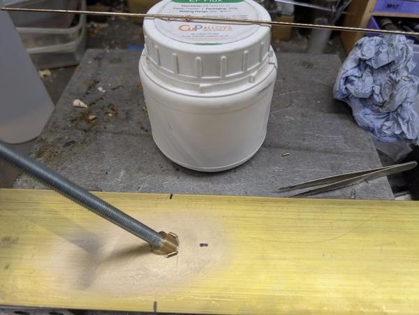
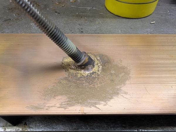
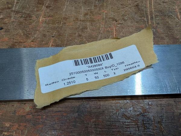
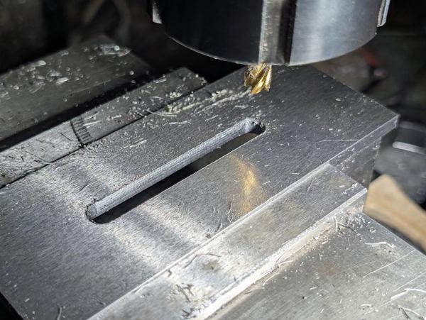
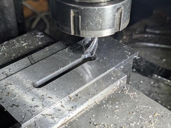
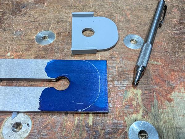
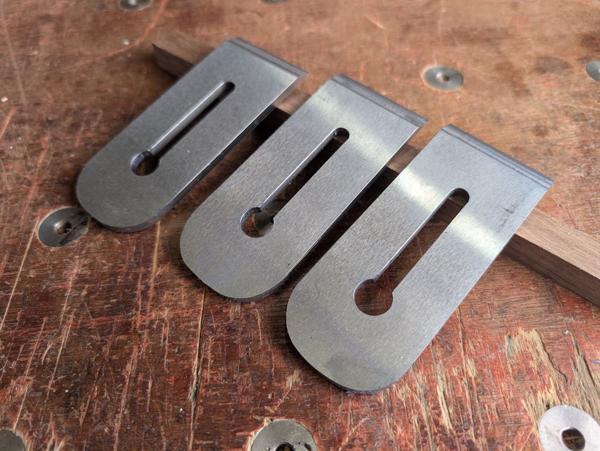
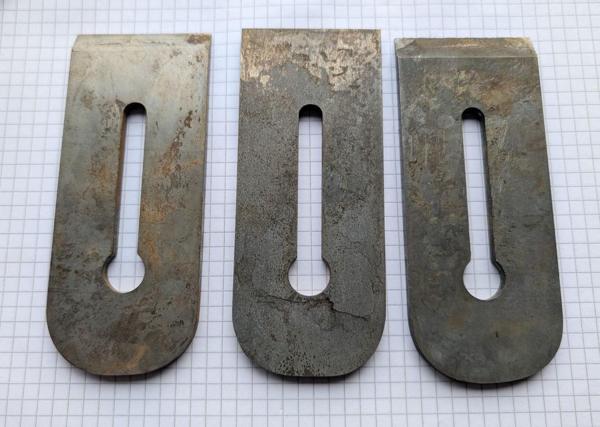
I'm aiming for a 70 mm body width, which means there isn't much excess material on the sides of that lump of rough-sawn beech. The brass plate is about 3 mm thick and 75 mm wide. I probably would have gone for a 75 mm body width by preference but I don't have any appropriate wood that is thick enough. The steel bar (gauge plate, also known as O1 tool steel) is 50 mm wide and 5 mm thick. I'm going to use that for the blade and also for a cap iron.

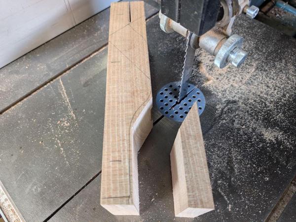
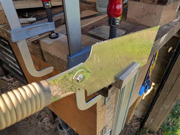
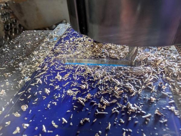
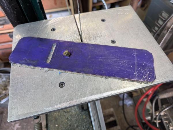
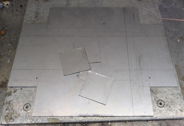
The first job (after spending quite a bit of time playing around with a CAD model, which I haven't completely finished yet) was to bandsaw the big lump of beech up:

2026-03-27-03-bandsawn_600.jpg


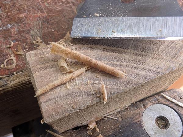
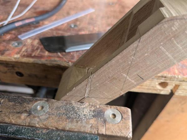
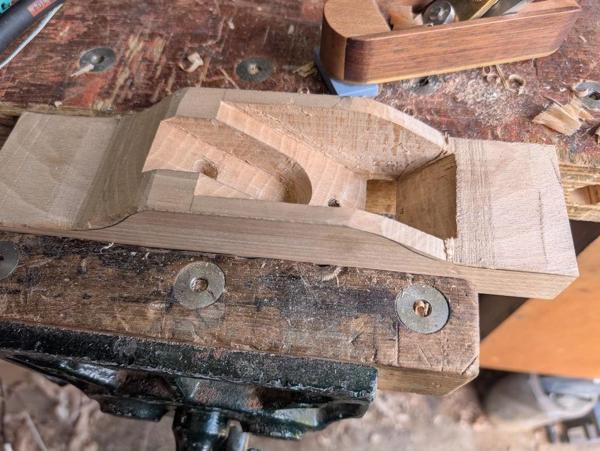
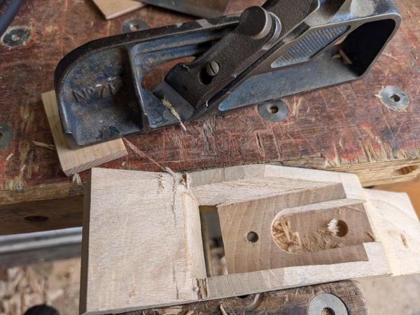
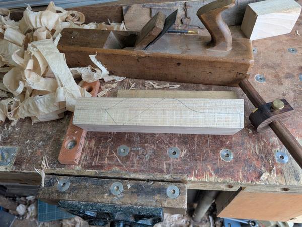
The base surface got planed flat with my wooden jack:

2026-03-27-04-planing_600.jpg


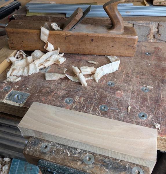
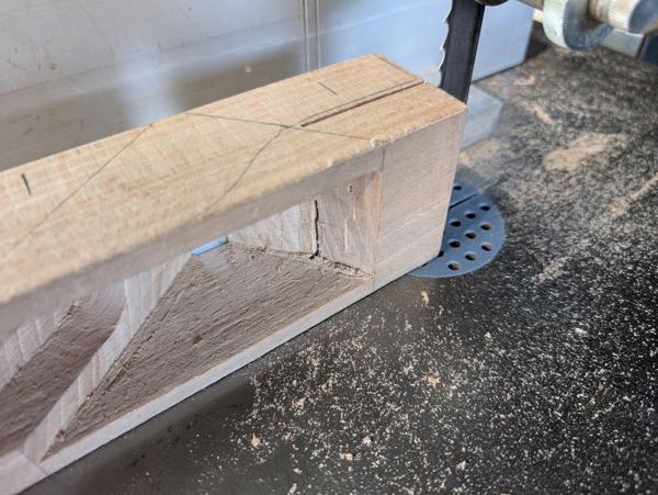
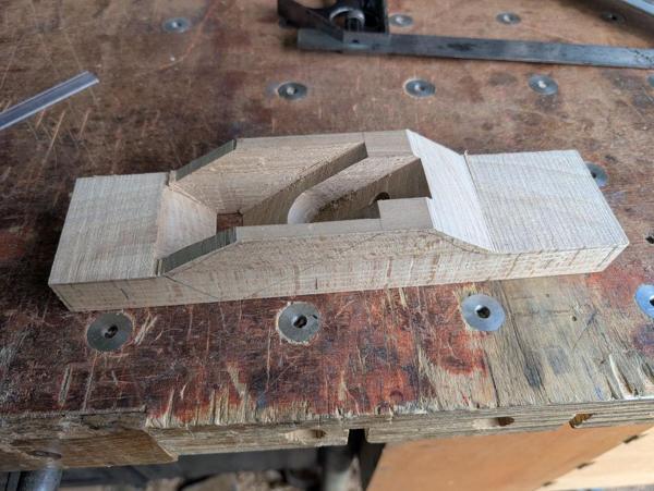
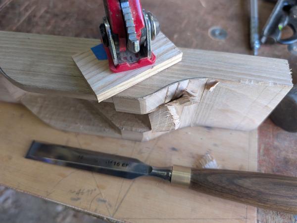
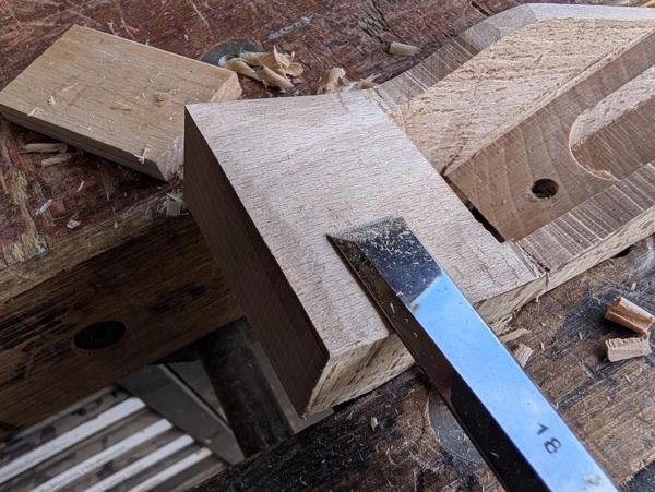
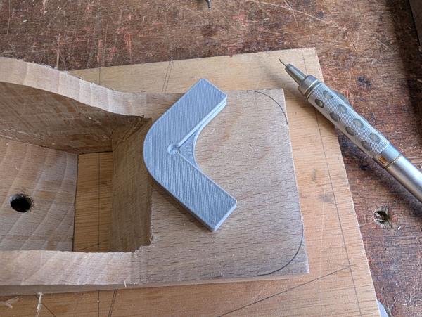
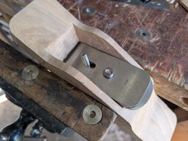
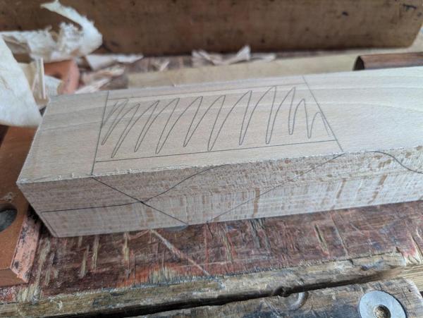
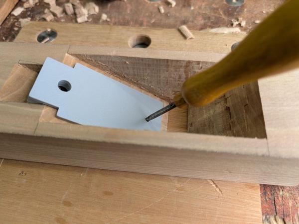
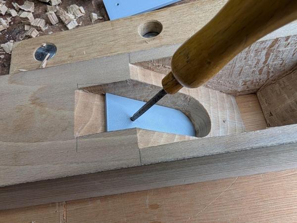
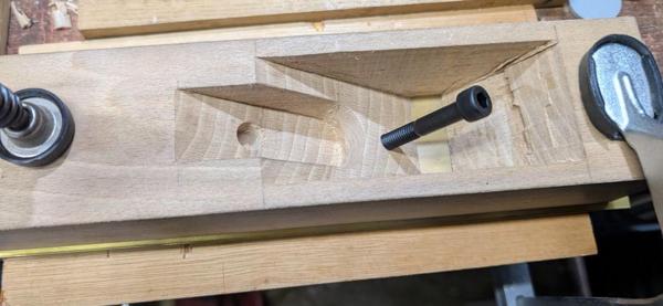
I've no idea why I did that in the vice rather than using planing stops, but it worked fine. I then very carefully planed down the sides so that they were square with the top, but taking as little off as possible to maximise the final width. I could then mark the shape of the body onto the side with a pencil:

2026-03-27-05-shape-marked-on-side_600.jpg


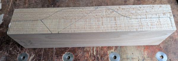
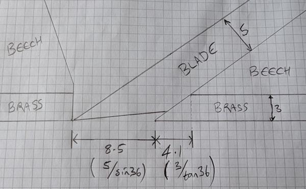
It's quite slim at front and back (25 mm plus the 3 mm brass thickness). Hopefully that will be enough for a strong enough body; I'm working on the assumption that the brass will help a lot with stiffness. Worst case I'll be thinking about a version 2 with steel sides but I'd rather err on the side of keeping the weight down for now.
 
Ooh, this is looking very interesting!
Will you use the brass sides to let you saw the escapement or will you make the conventional mortised escapement, with the sides adding extra strength (and bling!)?
 
Ooh, this is looking very interesting!
Will you use the brass sides to let you saw the escapement or will you make the conventional mortised escapement, with the sides adding extra strength (and bling!)?
The plan at the moment is to have a brass base and just the wood on the sides (a bit like the block plane I made but not laminated). If it isn't strong enough I'll have to add metal (steel or brass) on the sides but I'd rather keep the weight down if possible.

As for the big hole, that's a mortice chisel job. I'm not ruling out a final skim with the milling machine if I make a mess of the bed, but plan A is chisels and perhaps files.
 
Just in case you want to watch how wooden bench planes used to be made commercially, I'll take the risk of repeating myself and slip in a couple of my favourite archive video recommendations. I think they are worth a look even for people who don't have your appetite for testing new projects!

The classic offering from Ken Hawley is this one - Albert Bock, filmed on dodgy 16mm cine film in 1965, making bench planes at Marples, chopping out the escapement in the least time possible:


And less well known is this gem from Swiss TV, filmed in 1983, showing a father and son in their tool making shop in Geneva. Most of the stages of making a wooden jointer plane are included, with a strong sense of capturing a craft that was dying out.

It's doubtless more informative if you speak French, but stick with it even if you don't, as the film reveals so much.

 
Thanks Andy, they sound interesting. I'll probably wait until I've finished making mine before watching them: I quite like the process of figuring stuff out myself, especially once I've started a project. Of course that does mean I'll probably kick myself when I see all the better ways of doing things!
 
I had left the top surface of the plane body with a rough sawn finish but when I went back to it I decided it would be easier to plane it flat and parallel with the base and at about the right thickness for the widest part.

2026-03-27-06-planed-top-down-flat_600.jpg


With the height reduced and the top surface smooth I could mark out the big mortice on the top:

2026-03-27-07-marked-out-mortice_600.jpg


I'd wondered about cutting the profile into the top before starting the mortice, which would reduce the amount of material to remove and also reduce the risk of break-out when sawing the narrow side walls, but I decided that it was best to leave it solid for now and deal with the shaping later.

To cut the hole I used a 10 mm mortice chisel. After the first few whacks it looked like this:

2026-03-27-08-first-few-whacks_600.jpg


I went this far along before changing direction:

2026-03-27-09-just-about-to-change-direction_600.jpg


After coming back the other way the bottom surface was looking rough but it was getting quite deep (deeper than I realised in fact):

2026-03-27-10-messy-but-deep_600.jpg


Rather than carrying on deepening it with vertical chops, I switched to working down the angled faces. After the first go it looked like this:

2026-03-27-11-starting-to-clean-up_600.jpg


Unfortunately, I'd made two errors of judgement. The first was that I'd gone deeper than I'd realised. The second was that the front surface (the one the blade doesn't sit on) was steeper than I'd intended. As a result:

2026-03-27-12-whoops_600.jpg


That's not where it should be! Thankfully, I'd marked out that gap on the very conservative side (in practice it'll need to open out more or the blade will hit the front edge) and also at this point it's not too big a deal to move the hole slightly further forward:

2026-03-27-13-moved-hole-forward_600.jpg


That probably looks like a big hole for anyone used to wooden planes, but remember there's an additional 3 mm of brass thickness to go on the bottom and that'll close it up quite a lot.

There's a reasonably high chance that the error will mean that that the front section of the plane base (ahead of the blade) will be a bit shorter than I'd intended, but I don't think it's a disaster as the difference will only be a couple of millimetres.

With the bottom hole cleaned up, I could turn it back over and do a bit more cleaning up of the mortice. I pared the sides to something close to final dimension (they're now a fairly snug fit around the steel bar that'll become the blade but I'll probably open them up slightly more to give a bit of blade adjustment room). I've done a bit more paring down the long faces (with a 30 mm chisel, which I don't use much), but there's quite a bit further to go, especially on the surface that the blade will run on:

2026-03-27-14-stop-for-the-day_600.jpg
 
I deduce that this plane will have a screw to tighten against the iron, like your block plane. That's what you said at the beginning and it cunningly avoids the challenges of cutting abutments and making a wedge. Smart choice!
 
I deduce that this plane will have a screw to tighten against the iron, like your block plane. That's what you said at the beginning and it cunningly avoids the challenges of cutting abutments and making a wedge. Smart choice!

You're absolutely right. The plan is for a bit of threaded rod fixed into the beech body (just like the block plane) and a lever cap holding it all in place. I haven't quite figured out the design of the lever cap yet but there's plenty of time for that yet!
 
This morning I've been doing a bit more work on the body. I 3D-printed a guide (and later 3D-printed another thinner one) to help me get a consistent angle when tidying up the surface that the blade will sit on. No prizes for guessing what the bed angle of this plane will be:

2026-03-29-01-paring_600.jpg


The finished (for now) surface:

2026-03-29-02-finished-blade-surface_600.jpg


I then did a bit of (unguided) tidy up of bottom half of the front surface (which you can see is a bit shabby in the photo above) but I was being quite cautious not to open it up too much. The top half will get cut off later so I didn't bother to tidy that up. The bottom bit will probably get a bit more attention when the base is on and I've test-fitted a blade but I'll leave it for now. I didn't take any photos of that stage but you'll see it in some of the later ones.

The next thing to do was to make the pocket for the adjuster mechanism. To start the pocket off I angled the table on my pillar drill and used a 30 mm Forstner bit. I used a digital angle gauge to get the bed surface level and drilled down until the tip was a shade under 18 mm down:

2026-03-29-03-drilling-forstner_600.jpg


I also drilled a second hole with a 28 mm Forstner bit to clear out some of the waste:

2026-03-29-04-two-holes_600.jpg


It was then time for some more chiselling, using these three chisels:

2026-03-29-05-three-chisels_600.jpg


The 18 mm one did most of the work. The 8 mm one was used to get into the bottom of the curve and the carving gouge was used to extend the curve deeper into the wood (so I could get rid of the mark from the tip of the Forstner bit and bring the hole to depth).

That pocket is finished for now; the next job is to drill a couple of holes, one for the adjuster and one for the threaded rod that the lever cap will tighten against.

2026-03-29-06-done-for-now_600.jpg
 
These two little marking guides were very quick to design and only took about 10 minutes to print:

2026-03-29-07-two-marking-things_600.jpg


They line up with the pocket and allow marking of the hole for the threaded rod that will hold the blade down (via the lever cap)...

2026-03-29-08-mark-first-hole_600.jpg


and the hole for the adjuster:

2026-03-29-09-mark-second-hole_600.jpg


They got drilled in much the same way as before, with one difference on the lower hole, which I drilled through 6.8 mm...

2026-03-29-10-drilling_600.jpg


... and then flipped the plane over, lined the hole up again (using the drill which was still in the chuck) and plunged a 12 mm end mill into the bottom:

2026-03-29-11-end-mill-from-rear_600.jpg


On the little block plane, I set a piece of threaded rod into the body with a hole tapped into the wood and some epoxy to permanently mate the threads. That has worked absolutely fine on the block plane but I thought it would be good to try something a little stronger on this one.

I put a bit of 12.7 mm brass in the chuck of the metal lathe, skimmed the outside down to 12 mm and drilled and tapped an M8 hole in the middle:

2026-03-29-12-turn-and-tap_600.jpg


After coating the outside with some blue Dykem (and, as usual, not leaving it long enough to fully dry), I popped the brass bit into the hole in the bottom of the plane body and used my retractable scriber to mark around the level of the base of the beech block:

2026-03-29-13-mark-round-rim_600.jpg


The end then got sawn off with a hacksaw:

2026-03-29-14-hacksaw_600.jpg


I used a digital angle gauge to set a collet block up in the milling machine's vice at the right angle...

2026-03-29-15-angle-gauge_600.jpg


... and then milled down to the scribed line:

2026-03-29-16-mill-end_600.jpg


After deburring and washing off the Dykem with acetone, I held the part in the pocket in the bottom of the beech block (fingernail pressure was enough to hold it in place) and ran the M8 tap all the way through:

2026-03-29-17-tap-into-wood_600.jpg


That transferred the threads (nicely aligned) into the wood:

2026-03-29-18-threads-in-wood_600.jpg


Next up was to attach the angled nut to the brass base. This was the set-up I used for that:

2026-03-29-19-setup-for-alignment_600.jpg


The dial indicator stand is holding onto a bit of M8 threaded rod, which is long enough that I can sight along it's length and make sure the nut is pointing the right way. It's pressing it down fairly firmly to the brass plate (which has been scrubbed with Scotchbrite around the joint area) but I could slide the plate around underneath to tweak the position.

Flux was applied in the joint and some little bis of what I think is silver solder (it was found in an unlabelled tube in my father-in-law's shed) were dropped in three places around the joint:

2026-03-29-20-flux-and-solder_600.jpg


Lots of heat was applied with a MAPP gas torch until it all melted:

2026-03-29-21-lots-of-heat_600.jpg


It's not pretty, but no-one (apart from you, dear reader) will ever see it.

While that cooled down, I used a gouge to chamfer the hole in the bottom of the beech block (to give space for the melted solder bead to go). You can see the effect of not having waited for the Dykem to dry before putting the brass bit in for marking up:

2026-03-29-22-gouging-out-base_600.jpg


Finally, I could clamp the body down onto the brass plate and do a test fit with a handy cap screw:

2026-03-29-23-test-with-cap-screw_600.jpg


I was really pleased with how that came out. Being the only thing on the over-size plate, the alignment wasn't super critical. As on the block plane, I'll epoxy a bit of threaded rod into the hole when I get to final assembly, but the brass threaded bit at the bottom should be much stronger than just glue into threaded wood.

I haven't decided yet whether to do something similar with the front knob attachment or even the rear handle attachment. At the moment I'm leaning toward just attaching them from above (which will mean I don't have to worry about alignment relative to the existing parts) but we'll see.
 
Interesting project but I need to complain about your thread title - I have Santana stuck singing in my head now....
 
I spent most of yesterday blade making. This is the material I'm using:

2026-04-04-01-steel-for-blades_600.jpg


It's what's commonly known as gauge plate or O1 tool steel but more formally as Werkstoff 1.2510 and is an oil hardening (i.e. quenched in oil) steel supplied ground to size.

After chopping it up with the horizontal bandsaw, I used a little 3D-printed marking guide to help punch a series of evenly spaced marks along the middle of the blank:

2026-04-04-02-3d-printed-punch-marking-guide_600.jpg


Those made it easy to use the pillar drill to spot drill and drill through 7 mm with all the holes centred and without any risk of the holes joining and deflecting the drill bit:

2026-04-04-03-chain-drilling-on-pillar-drill_600.jpg


It then went over to the milling machine and I used a 7 mm end mill to join the holes together...

2026-04-04-04-milling-7mm_600.jpg


... before swapping to an 8 mm end mill for a couple of final passes, opening the slot out to 8.5 mm width:

2026-04-04-05-milling-8mm_600.jpg


One end got opened up with a 12 mm end mill and then a 14 mm one:

2026-04-04-06-opened-end-out_600.jpg


Next I mounted the blade in the milling vice at an angle:

2026-04-04-07-angled-blade-for-bevel_600.jpg


The bed angle is 36° and (if I understand correctly) on a bevel down plane it doesn't really matter what the bevel angle is as long as it's a few degrees less than the bed angle (for clearance). The bed angle dictates the cutting action. I've milled it at 24°; I'll probably grind a primary bevel at 25° and then put a secondary bevel on at 30° which will make the tip a little stronger but still leave 6° of clearance.

With it mounted at the chosen angle, I milled it down until there was a bit under a millimetre left at the end. I think there's a higher risk of distortion if you heat treat it with a razor edge, but milling most of it off saves a lot of post-hardening grinding work.

2026-04-04-08-leave-a-bit-for-grinding_600.jpg


The shape of the rear end of the blade isn't that critical but I drew something that looked okay to me in CAD and 3D-printed a little marking guide and used that and my home-made retractable scriber to mark a desired shape:

2026-04-04-09-mark-round-back-edge-with-template_600.jpg


I used my home-made table for the metalwork bandsaw to remove most of the waste:

2026-04-04-10-bandsaw_600.jpg


Then filed down to somewhere near the line, starting off with this bastard cut file...

2026-04-04-11-filing_600.jpg


... and then finishing with a 2nd cut and then a smooth cut one.

The blade ready for heat treatment (and probably the last time it will look this shiny):

2026-04-04-12-first-blade-ready-for-heat-treatment_600.jpg


Ctrl-C, Ctrl-V, Ctrl-V:

2026-04-04-13-three-blades_600.jpg


When heating steel to red hot in air, it develops some scale on the surface and that can be very hard to remove. To avoid that I tend to bury the parts in boric acid powder, which protects them from scaling and coats them in a glassy substance that can be easily removed with boiling water. I'd previously used a small welded tray to hold the parts and the boric acid but it wasn't big enough to put all three blades in, so I grabbed a handy bit of sheet steel and cut it into a pattern:

2026-04-04-14-tray-pattern_600.jpg


The pattern got folded with my home-made sheet metal bender:

2026-04-04-15-folded_600.jpg


Four short TIG welds later it was ready for use:

2026-04-04-16-welded_600.jpg


I'd made that little tray before retrieving my home-made heat treatment oven from storage. Having got it back I realised it was a very close fit in the cavity:

2026-04-04-17-just-fits_600.jpg


At that point I felt grateful that there's an interlock on the door so the power is automatically removed from the elements when you open it! In the photo above, you can see the boric acid in the tray, covering the three blades. A bit later, it looked like this:

2026-04-04-18-hot-hot-hot_600.jpg


One-by-one, the blades were removed from the oven and quenched in a tall Kilner jar (something like this) full of vegetable oil. After cleaning the boric acid off with boiling water, they then went in the kitchen oven at 200°C for an hour or so to temper.

They don't look as shiny now:

2026-04-04-19-post-heat-treating_600.jpg


The next job is lots of deeply dull work with wet-and-dry paper to clean them up.
 
Sorry for asking the bone-headed questions, but what’s the purpose of each heating?
It's not bone-headed at all: it's a perfectly reasonable question.

The first heat (up to about 800°C or so) makes the blade glow a cherry red. Internally it changes the structure of the steel. Dunking it in oil cools it rapidly, "freezing" that new harder structure.

The steel is then what is often referred to as "glass hard": it's extremely hard but also brittle and likely to break.

The second heat (at 200°C or so) is called tempering and softens it very slightly while adding a lot of durability: effectively keeping most of the hardness while getting rid of the brittleness.

Does that make sense?
 
Good explanation. First explained when I was a nipper in metalwork class - before I was mad to do exclusively academic stuff. They had a proper old fashioned forge and we did heat treatments.
 
It's not bone-headed at all: it's a perfectly reasonable question.

The first heat (up to about 800°C or so) makes the blade glow a cherry red. Internally it changes the structure of the steel. Dunking it in oil cools it rapidly, "freezing" that new harder structure.

The steel is then what is often referred to as "glass hard": it's extremely hard but also brittle and likely to break.

The second heat (at 200°C or so) is called tempering and softens it very slightly while adding a lot of durability: effectively keeping most of the hardness while getting rid of the brittleness.

Does that make sense?
Yes, it makes sense. Thanks. I have supplementaries though:

What state is the tool steel delivered to you? You said it’s oil quenched, so does that mean it’s hard? Are you doing the heating because the steel as delivered isn’t the right hardness/brittleness or because your tooling operations changed it (or a bit of both)?

You’re heating the entire blade. Is that because it’s important for the characteristics you’re looking for throughout the blade or is it because that’s easier than only heating part of the blade (or for some other reason)?

Thats all I’ve got for now. Really appreciate you writing about this. It’s fascinating.
 
Fascinating as ever Al thanks. Saw a guy using a wheel to clean rust off tools, bit like a polishing mop but brown, made of stuff like a green kitchen scourer. It was extremely effective would that work to clean them up? Or is this stuff too hard?
 
What state is the tool steel delivered to you? You said it’s oil quenched, so does that mean it’s hard? Are you doing the heating because the steel as delivered isn’t the right hardness/brittleness or because your tooling operations changed it (or a bit of both)?

It's delivered soft, which is what you want as otherwise it would be next to impossible to shape it (e.g. cutting the slotted hole). Hardening at the end turns it into a cutting tool. I still find it slightly amazing that you can buy a bit of soft steel, cut it in half, shape one half into a cutting tool and harden & temper that half, then use the hardened half to cut and shape the soft half. I sort-of understand some of the science behind it but the kid in me still finds the whole thing magical.

You’re heating the entire blade. Is that because it’s important for the characteristics you’re looking for throughout the blade or is it because that’s easier than only heating part of the blade (or for some other reason)?

Most of the blades I've made in the past have been heated with a blowtorch (or for something this size, often two blowtorches!). The aim with a blowtorch is to get the very tip hot as that's the only bit you really need hard. The downside of that is the uneven heating can introduce distortion. There's always a bit of distortion but the more uneven the heat the more distortion you get. The nice thing about using an oven like mine is it heats the entire blade evenly, which should minimise the distortion.

I've been rubbing the blades on wet-and-dry paper on glass today and, while it still took a while and was mighty tedious, it was far quicker than any blade of this size I've made before. I suspect that was down to the even heating.

Fascinating as ever Al thanks. Saw a guy using a wheel to clean rust off tools, bit like a polishing mop but brown, made of stuff like a green kitchen scourer. It was extremely effective would that work to clean them up? Or is this stuff too hard?

Yes, that would work, but it would take a long time to get it flat (and the fact it's typically a rotating wheel means it's would be hard to get a flat surface if that's what you're aiming for). Those polishing mop compounds and Scotchbrite pads tend to be quite fine grits so they don't remove much steel (which is good if you just want to get rid of the rust but bad if you want to flatten things and get rid of any heat oxidation, which tends to be a lot harder than rust).

I'm saying all this like I know what I'm talking about but most of it is just stuff I've figured out from trial and error so it's entirely possible that everything I've written in this post is wrong!
 
Last edited:
Fascinating as ever Al thanks. Saw a guy using a wheel to clean rust off tools, bit like a polishing mop but brown, made of stuff like a green kitchen scourer. It was extremely effective would that work to clean them up? Or is this stuff too hard?
Scotch-brite mops?... I must have seen that video you've mentioned Ian. Cleaning up a small (½" possibly) chisel..? Different grades available... something I'll have to get at some point.
 
It's delivered soft, which is what you want as otherwise it would be next to impossible to shape it (e.g. cutting the slotted hole). Hardening at the end turns it into a cutting tool. I still find it slightly amazing that you can buy a bit of soft steel, cut it in half, shape one half into a cutting tool and harden & temper that half, then use the hardened half to cut and shape the soft half. I sort-of understand some of the science behind it but the kid in me still finds the whole thing magical.


Most of the blades I've made in the past have been heated with a blowtorch (or for something this size, often two blowtorches!). The aim with a blowtorch is to get the very tip hot as that's the only bit you really need hard. The downside of that is the uneven heating can introduce distortion. There's always a bit of distortion but the more uneven the heat the more distortion you get. The nice thing about using an oven like mine is it heats the entire blade evenly, which should minimise the distortion.

I've been rubbing the blades on wet-and-dry paper on glass today and, while it still took a while and was mighty tedious, it was far quicker than any blade of this size I've made before. I suspect that was down to the even heating.


Yes, that would work, but it would take a long time to get it flat (and the fact it's typically a rotating wheel means it's would be hard to get a flat surface if that's what you're aiming for). Those polishing mop compounds and Scotchbrite pads tend to be quite fine grits so they don't remove much steel (which is good if you just want to get rid of the rust but bad if you want to flatten things and get rid of any heat oxidation, which tends to be a lot harder than rust).

I'm saying all this like I know what I'm talking about but most of it is just stuff I've figured out from trial and error so it's entirely possible that everything I've written in this post is wrong!
Thanks again. I don’t know anything about metalwork - as you can tell - but I was watching a Marius Hornberger video recently and he kept talking about distortion that could be brought on by welding which wasn’t something I’d thought about before. I should have thought about it in this context too. Thanks for making the connection for me.
 
Thanks again. I don’t know anything about metalwork - as you can tell - but I was watching a Marius Hornberger video recently and he kept talking about distortion that could be brought on by welding which wasn’t something I’d thought about before. I should have thought about it in this context too. Thanks for making the connection for me.

Welding distortion is even more dramatic than the distortion you get when heat treating. The way it was explained to me is that welding involves melting steel and using the melted steel to make a joint. Steel expands at about 12 ppm/°C (from memory). Stainless steel about 16 ppm/°C. What those numbers mean is that for every degree you heat steel up, it'll grow in size by 12 μm in every metre of length. That doesn't sound much, but heat it up to melting point (about 1500°C) and it grows by 18 mm in every metre of length. Of course the molten bit is a lot less than a metre long but the growth is still quite significant proportion. You weld it in the position you want it when the weld bead is molten and then the weld bead shrinks as it cools. The shrinkage pulls the metal over towards the weld bead and away from where you wanted it to be.

As a result if you prepare a right angle joint and weld along the inside corner, the cooling weld bead will cause the angle to close up. Some experienced welders (not me!) can weld things at deliberately the wrong angle and then watch as the cooling action brings it perfectly square.
 
Most of the morning was spent finishing off the blades. It all started with some 120 grit wet-and-dry paper on a piece of glass (acting as a flat reference surface):

2026-04-04-10-wet-and-dry-on-glass_600.jpg


I used that on both faces and all the way round the rim but didn't touch the bevel at this point. I kept going until most of the surface was smooth but didn't try to get rid of every blemish (as I don't have the patience for that). The flat side then got rubbed on 240 grit wet-and-dry paper. The aim here is to get rid of all the 120 grit marks and leave a smooth surface near the cutting edge.

In practice, what happens is that it'll either get ground at the tip and at the back or it'll get ground in the middle. The former case is good; in the latter case I keep going until it's at least most of the way to the tip. In the following photo, the two on the right are what I consider to be good enough. The one on the left isn't great (as there are still some coarse marks in the middle of the tip area) but it'll do.

2026-04-04-11-good-enough_600.jpg


Next up is some work on my medium speed bench grinder, to prepare the bevel. This proceeds quite quickly, with the blade being dunked in some water as soon as the blade starts to feel even slightly warm.

2026-04-04-12-grinding-bevel_600.jpg


Looking at that photo, the blade tip looks a bit red (albeit a bit of a weird shade). That's not a heat effect, I think it's probably a reflection of something.

This is what it looked like when the grinding was nearly done:

2026-04-04-13-grinding-nearly-there_600.jpg


If you look closely you can see there's still a very slight flat end, so a bit more grinding was needed to remove that.

With the grinding complete it was over to the bench stones:

2026-04-04-14-honing-guide_600.jpg


There are a lots of ways of sharpening. As long as you get a sharp edge then your method is fine. This is just my method.

I use an Eclipse #36 honing guide, which I find is the quickest option for preparing bevels where there's a reasonable amount of material to remove (and I find it no slower than doing it by hand for normal sharpening). While putting the blade into the guide adds a bit of time (of the order of 15 seconds) to the process, I can move the blade back and forth on the stone at about 3 to 4 times the speed than I can when doing it unguided. As a result, the actual time on the stones is much shorter and that compensates for the jig set-up time.

After working through the three stones - a "coarse" diamond stone (equivalent to 325 grit I think), an "extra" fine diamond stone (equivalent to 1000 or 1200 grit I think) and an 8000 grit waterstone (which unlike the coarser waterstones doesn't need the tedious and messy step of soaking it in water, just spraying it is enough) - I plonk an old steel rule down on the waterstone and use David Charlesworth's trick to make sure the very tip is polished despite the slightly rough grinding in the earlier photo:

2026-04-04-15-ruler-trick_600.jpg


This is what the ruler trick does to the back:

2026-04-04-microbevel_600.jpg


This is the blade with the slightly lower middle section (because I stopped flattening before it went all the way to the tip). You can see that the polished edge only just makes it to the tip in the central section (whereas at the edges it goes further back). Only just getting to the edge is enough as it's only the very tip that cuts.

The blade then gets stropped on the leather pad and is ready to cut:

2026-04-04-16-ready-to-cut_600.jpg


It'll probably go back to the waterstone later to have a bit more attention on the bevel with more pressure on the outer edges (to add a very slight camber). For now I've just sharpened it straight across so any out-of-squareness of the blade fitment in the plane body will result in scratches from the corners of the edge. For now it's good enough to prove that the blades cut:

2026-04-04-shaving-end-grain_600.jpg


That was just a quick test freehand on some end grain (I think it's Sweet Chestnut). Plane blades aren't the most ergonomic thing to use freehand but it cut easily and that's good enough for me.

All three blades are finished, give or take any cambering or whatever I decide to do later:

2026-04-04-three-sharp-blades_600.jpg
 
Have I missed something? Why are you making 3 blades?

Mainly just because it's not that much more work (ignoring the tedious flattening on glass process) to make three than it is to make one. A lot of the work ends up being in setting up machines, zeroing axes etc and once you've done that for the first blade then (assuming they're all the same size) you might as well work on several blanks.

When I made my block plane I made two blades and similarly when I made Paul Sellers' design of router plane, I did the same. It's sometimes handy to have spare blade if only because you can quickly swap them out and then sharpen both later. For home-made blades I generally figure that I'd like to have a spare in case I do anything stupid and mess one of them up or if one distorts so much that I can't face the work involved in flattening it.

Three blades is perhaps excessive, but I'm planning on grinding a different tip shape on one of the blades (you'll have to wait for a later episode for an explanation of that). If that doesn't prove beneficial then I'll still have two blades that I can swap between.
 
I thought as much TBH but was hoping you were going to make another couple of planes.
We often hear of different planes with different bed angles which just got be thinking if an adjustable bed was possible by way of various inserts.
 
I thought as much TBH but was hoping you were going to make another couple of planes.

I'm sure I'll make more at some point, but not for a while.

We often hear of different planes with different bed angles which just got me thinking if an adjustable bed was possible by way of various inserts.

Hold that thought... 😉
 
I'm enjoying this... but I've lost count of the number of homemade tools you have used so far. The satisfaction index must be nearly at the top of the scale!
 
I'm enjoying this... but I've lost count of the number of homemade tools you have used so far. The satisfaction index must be nearly at the top of the scale!
Absolutely. I love making tools & then being able to use them to make more tools. There are a few that I've used but not explicitly mentioned (e.g. the bench grinder's support bar & mount, the "welder's third hand" etc), but I've tried to mention most of them whenever I remember.
 
Scotch-brite mops?... I must have seen that video you've mentioned Ian. Cleaning up a small (½" possibly) chisel..? Different grades available... something I'll have to get at some point.
Yep that was the one.
That bevel was most definitely a whole lot more perfect than my old flat revolving wheel did. I’ve just bought a slow Tormek style water cooled wheel but haven’t used it yet.
 
Another steel milling job that needed doing was to make the cap iron. The process for this was quite similar to that for the blades except that I didn't use the pillar drill but went straight to the milling machine:

2026-04-04-cap-iron-01-milling-holes_600.jpg


I'm shaping the cap iron to be a bit like a blade but it won't get hardened as it isn't actually cutting. I cut a bevel on it at the final intended angle:

2026-04-04-cap-iron-02-bevel-angle_600.jpg


The back got shaped in the same was as the blades but with a slightly different shape for no particular reason:

2026-04-04-cap-iron-03-back-shaped_600.jpg


Most cap irons I've seen have a slightly curved shape. The intention of the curve is that, when they're clamped down to the blade, the tip is forced into tight contact with the flat surface of the blade and causes shavings to be deflected by the cap iron rather than getting jammed underneath it.

I've decided to stick with a flat cap iron for this plane (although if it causes problems later I can always come back and modify it or make a new one). As it won't have been hardened, I should be able to slightly deform the very tip with a hammer (like the process done on soft-backed Japanese chisels) so that the very tip is ever so slightly curved down but the rest of the cap iron is flat (and that deformation can be quickly re-done if the cap iron bends back). All being well, that'll serve the purpose of giving a tight contact between the blade and the cap iron but without the hassle of making a fully curved part. I won't know the outcome of that until I've finished making the plane, but that's the plan for now.

To attach the blade to the cap iron, I needed to do a very simple turning job:

2026-04-04-cap-iron-04-simple-turning-job_600.jpg


That's 13 mm diameter, reducing to 11 mm at the tip. It has a 6.8 mm through hole. My favourite metal glue got used to fix that into the little pocket in the cap iron:

2026-04-04-cap-iron-05-glued-in_600.jpg


Once the glue had been left for plenty of time to set, I clamped the turned part in the bench vice and the tapped M8 through both together:

2026-04-04-cap-iron-06-tapped-together_600.jpg


A quick test fit showing the cap iron mounted to a blade:

2026-04-04-cap-iron-07-mounted-to-blade_600.jpg


As you can see, I made this cap iron before heat treating the blades (as the process of making the cap iron was quite similar to that of the blades so it made sense to do them at the same time) but I thought I'd post about it separately as it's a distinct part.
 
This morning I've been working on the body again. The first job was to get rid of some of the waste that comes as a result of the curvy top shape I've picked. I started by cutting along the straight bit at the front with the bandsaw, stopping just as the blade came into the opening (so the blade didn't make too much of a mess of the unsupported top web):

2026-04-05-01-bandsawing-front-of-body_600.jpg


The back was simpler and I could just cut a section out with the bandsaw:

2026-04-05-02-bandsawn-back-of-body_600.jpg


To remove the back piece, I sawed down each side separately with the Dozuki:

2026-04-05-03-dozuki-for-the-thin-bits_600.jpg


That gives an idea of the rough shape that the plane will be:

2026-04-05-04-rough-shape_600.jpg


I squared up the front end using my shooting board and low-angle jack plane (equipped with my home-made shooting handle):

2026-04-05-05-shooting-ends_600.jpg


The back got shortened a bit...

2026-04-05-06-shortening_600.jpg


... before it too was subjected to the shooting board.

For the convex bits of the curves and the outer areas of the flat bits, I used my home-made block plane:

2026-04-05-07-block-plane_600.jpg


I was quite nervous about the concave areas as I've never felt very confident dealing with the transition between grain going down the curve and (on one end) grain going the other way along the face. I started by putting the body on its side and chopping down with a chisel to get rid of the bulk of the waste:

2026-04-05-08-chopping-out-bulk-of-waste_600.jpg


A bevel-down chisel then did a lot of the remaining work down to the flat:

2026-04-05-09-bevel-down_600.jpg


In that photo you'll notice a bit of tear out where I forgot to chamfer (what was then) the rear side before planing across the grain with the block plane. It's not a big deal as I intend to round that edge off quite a bit when the plane is closer to finished.

To deal with the flat bit that the block plane couldn't get to (near the transition to curved) I thought I'd pull out one of my most infrequently used tools: the Record #73 shoulder plane. That brought the surface down closer to the line, but I quickly reminded myself why I don't use it very often.

2026-04-05-10-shoulder-plane_600.jpg


To tidy up my rough bevel down chiselling and rough shoulder planing, I used the wonderful get-out-of-jail free card that is a card scraper to tidy the back surface up:

2026-04-05-11-card-scrapers_600.jpg


For the front surface, I thought I'd try a different shoulder plane, this one with a skewed blade with the skew in the right direction (for the front of the plane) to make a fairly smooth cut:

2026-04-05-12-different-shoulder-plane_600.jpg


In the end, however, I did what I usually end up doing when experimenting with shoulder planes and went back to using a chisel instead:

2026-04-05-13-chisel-is-better_600.jpg


The sloping walls were a bit easier this time (as they are thinner and the grain direction is such that the chisel can keep going when it meets the face), so a bevel down chisel followed by a light touch with a card scraper sorted it out.

Next up was to round off the corners. I marked a 16 mm radius with this little printed guide:

2026-04-05-14-marking-corners_600.jpg


A few years ago the only way I would have thought myself capable of rounding a corner like that would have been with an electric router and a template. It's much more pleasant just doing it with a chisel:

2026-04-05-15-chiselling-corners_600.jpg


With all that done, I could tidy up the side walls a bit more and then do a test fit of the blade:

2026-04-05-16-blade-test-fit_600.jpg


I can't fix it in place yet as there's no lever cap (and I haven't even figured out the design of the lever cap yet - that's a problem for later down the line).

With hindsight I think it would have been better to move the threaded rod location a bit higher up the slope and/or lengthen the slot further. With the blade and cap iron pulled back as far as possible (as shown in that photo), the blade protrudes 2.5 mm out of the bottom of the body. That should be just okay as the brass base is currently 3.2 mm thick so even after attaching it and removing a bit of material through flattening the blade should still be retractable to the point that it doesn't cut.

If it proves to be a problem I can extend the slot in the cap iron (which will remain unhardened) and grind a bit more off the tip of the blades, but I think it should be okay.

Another quick job before moving onto the next thing: drilling an 8.2 mm hole (clearance for M8) in the front:

2026-04-05-17-drill-hole-for-knob_600.jpg


It then got flipped over and an 11.1 mm hole drilled 12 mm deep followed by a 14 mm end mill (still in the pillar drill) drilling clearance for the head of a threaded insert:

2026-04-05-18-threaded-insert_600.jpg


In most situations, inserting a threaded insert from the rear isn't a very good idea as tightening the screw from the other end can also untighten the threaded insert. In this case I think it's okay as the brass base will stop that threaded insert from going anywhere.

A few days ago, I'd coated the brass base with Dykem. With the basic outside shape of the plane defined, I could plonk it on top of the brass piece and draw around it:

2026-04-05-19-place-for-marking-brass_600.jpg


The result:

2026-04-05-20-marked-brass_600.jpg


That mouth opening is the maximum size at the upper face. It'll be a lot smaller on the bottom face (the 36° bed angle and 3.2 mm thickness equates to a 4.4 mm reduction in size and there will be a smaller reduction at the front too). I think I'll probably drill or mill it out quite a bit smaller than I expect it to end up. As much as I dislike filing, I think the only way to get the right shape for the mouth will be needle files (all the bigger files I measured were 5 mm thick, which is the same as the blade thickness and hence too thick for filing a close-fitting opening for the blade).
 
Before cutting the slot in the brass, I thought I'd do a little 5:1 pencil sketch to work out the size of the slot at the bottom and also how far ahead of the bottom of the beech slot the hole needs to be. I did the calculations based on 3 mm thick brass (rather than 3.2 mm) to allow for any reduction in thickness from the flattening process.

2026-04-05-21-pencil-sketch_600.jpg


That told me that the slot would be 8.5 mm wide (plus any allowance for shavings) so it's safe to mill a 6 mm slot:

2026-04-05-22-milled-pocket_600.jpg


I then covered the bottom surface in masking tape (to minimise the risk of brass chips gouging the underside) and used the bandsaw to bring the brass piece closer to the final size:

2026-04-05-23-bandsawn_600.jpg


Six holes were made in the brass plate, starting with a 6 mm spotting drill to get a shallow countersink:

2026-04-05-24-spotting-drill-with-eerie-shadow_600.jpg


Sorry about the weird effect on the right-hand side of that photo. After taking the photo I checked the lens of my phone camera for dirt and realised there was a massive crack covering most of it. Thankfully I've got a screen protector thing on it and it was only the protector that was cracked but the rest of the photos in this post were taken before replacing the protector, so you might see some weird effects in later photos where I haven't cropped it out.

After using the spotting drill, I switched to a 4.1 mm drill bit and drilled through:

2026-04-05-25-drilling-through_600.jpg


A 4 mm transfer punch was used to transfer the marks onto the beech body...

2026-04-05-26-transfer-punch_600.jpg


... and then a pilot drill prepared the holes for their screws:

2026-04-05-27-pilot-drill_600.jpg


After cleaning off all the Dykem with acetone, I roughed up the surface with some 150 grit sandpaper to give the epoxy something to stick to:

2026-04-05-28-roughing-surface-for-glue_600.jpg


Everything prepared and ready to glue:

2026-04-05-29-ready-to-glue_600.jpg


I'm using off-the-shelf brass wood screws which seem to always come with horrid slotted heads. On the up-side though, that means I can use my home-made screwdriver to tighten them up. The beech got daubed in epoxy, keeping the pocket for the brazed-on nut thing clear. There was a bit left-over so I spread it round the outer rim on the brass as I figured it couldn't hurt.

2026-04-05-30-daubed-in-epoxy_600.jpg


The six brass screws then got tightened into the holes. Five of them went well. The other not so much:

2026-04-05-31-drat_600.jpg


I'd considered pre-screwing the holes with some steel wood screws (to give the brass an easier life) but none of my steel screws have the same pitch thread as these brass ones so I thought it would probably be a bad idea.

I didn't have any bigger brass wood screws so the only thing I could think to do was to drill the broken screw out with a 4.2 mm drill bit...

2026-04-05-32-drilled-out-broken-screw_600.jpg


... then tap the resulting hole M5. An M5 thread in wood isn't going to be that strong but I'm hoping that the combination of the M5 thread and a lot of epoxy might be better than nothing.

I don't have any M5 countersunk machine screws, but unlike wood screws, machine screws are easy to make:

2026-04-05-33-m5_600.jpg


I could have just left the body as a cylinder and tightened with pliers but I figured I might as well use my home-made (from a Hemingway kit) rotary broach and then I could use an Allen key to fit the screw (after daubing it in epoxy:

2026-04-05-34-custom-screw_600.jpg


I'll leave it overnight now and then try to clean up that screw head first. If it comes out or breaks off then I'll probably make or buy a much bigger diameter wood screw and find a way to fit it and fill the hole.
 
I think there are quite a few of us on here who would be only too happy to send you a selection of suitable screws, but on a holiday weekend, making your own is much quicker!
 
"......machine screws are easy to make". :D

I bet you've got lots of friends who want odd favours doing now and then, or more often. "Hey Al, could you just.......?" You ought to consider yourself lucky you don't live near me!!!
 
I've just realised something Al. I should have asked about it sooner, but I was distracted by all the activity and the photos and wasn't paying proper attention. But now I belatedly realise that this plane is getting a sole made of brass.

You probably already know this and have a plan in mind, but brass soled planes are unusual. The reason is that the relatively soft brass can leave black marks on the wood being planed.

Sometimes you'll see brass cast planes with a thin steel sole sweated on, as a way of avoiding the problem.

I hope something is in your plans and I'm not spoiling anything but I feel duty bound to ask if you intend to add anything on to the sole or treat it in some way, or just call this an experiment to see if it really matters.
 
Back
Top