• Hi all and welcome to TheWoodHaven2 brought into the 21st Century, kicking and screaming! We all have Alasdair to thank for the vast bulk of the heavy lifting to get us here, no more so than me because he's taken away a huge burden of responsibility from my shoulders and brought us to this new shiny home, with all your previous content (hopefully) still intact! Please peruse and feed back. There is still plenty to do, like changing the colour scheme, adding the banner graphic, tweaking the odd setting here and there so I have added a new thread in the 'Technical Issues, Bugs and Feature Requests' forum for you to add any issues you find, any missing settings or just anything you'd like to see added/removed from the feature set that Xenforo offers. We will get to everything over the coming weeks so please be patient, but add anything at all to the thread I mention above and we promise to get to them over the next few days/weeks/months. In the meantime, please enjoy!

A groovy little two-day project

Dr.Al

Old Oak
Joined
Dec 31, 2020
Messages
3,827
Reaction score
2,717
Location
Dursley, Gloucestershire
Name
Al
I've just finished this simple project but I thought I'd post it in three instalments just to spread it out a bit.

About five years ago, I made a set of grooving planes based on an idea from Matthew Kenney in a book on woodworking with hand tools. I use the four planes fairly often as they're really convenient, involving zero set-up. Here they are next to all of my other plough planes:
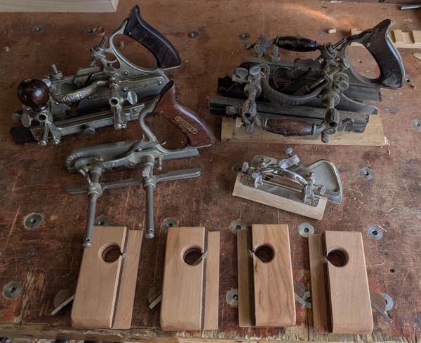
plough-planes_600.jpg


That's probably more plough planes than anyone needs, but I've though for a while that it would be handy to have a pair of 4 mm grooving planes to go with the 3 mm and 5 mm ones. I've been using the #43 quite often (with a 4 mm cutter) and as it's a size I use a lot then the fixed one would add convenience. The plane will cut a 4 mm wide groove, 4 mm deep at a 4 mm offset from the edge of the board.

If I'm honest, I don't really remember the process I went through to make those planes (it was before I was in the habit of writing up my builds in detail). My webpage about the planes says "Although I tweaked all the dimensions etc, the construction method and general principle follow Matthew Kenney's approach very closely", so I could look it up in the book but what I do remember is that it involved lots of use of the table saw and the electric router and I don't want to use them this time so I'm going to go my own way.

Another thing I remember about the process is that it was quite fiddly and time consuming at the end as the central piece of wood was either too thin to allow the blade to enter the slot or too thick to go into the groove made by the blade. I ended up doing a lot of fettling with needle files to make it work. This time I'm going to try a different approach.

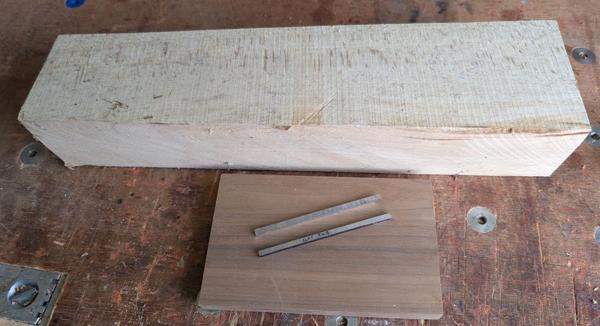
I started with these raw (ish) materials:
2026-08-02-01-raw-ish-materials_600.jpg


That's a big lump of Beech, a small piece of American Black Walnut and a piece of 3 × 4 mm high-speed steel that's been cut in half. One half has already been shaped into a blade (more on that later), the other half is largely untouched,

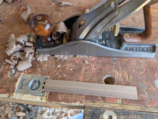
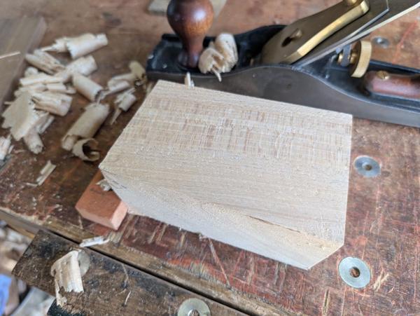
The first job was to cut off the end of that bit of beech and then plane three sides with my Axminster #5:
2026-08-02-02-planing-end-bit-of-beech_600.jpg


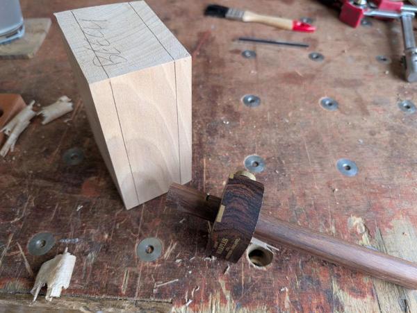
A pin marking gauge was used to mark 12 mm all the way round from each side of the block:
2026-08-02-03-marked-all-round_600.jpg


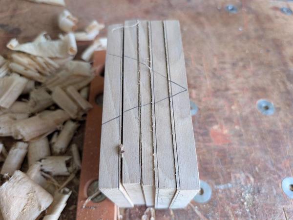
It was then sliced up on the bandsaw a little way from the line, then planed again, then marked again (10 mm this time), then sliced up on the bandsaw again, resulting in this:
2026-08-02-04-sliced-up_600.jpg


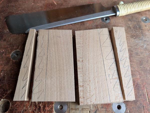
Lots more planing (this time with a Clifton #4½) brought all the pieces down to the marked lines:
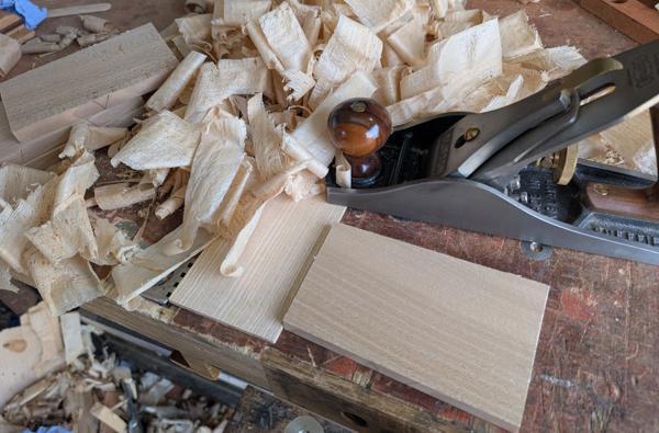
2026-08-02-05-more-planing_600.jpg


For the Walnut piece, I want it to be ever-so-slightly thicker than the blade. If it's thinner than the blade then it'll be impossible to get the blade into the opening. To aid that, I used the blade as a reference and set the pin gauge up like this:
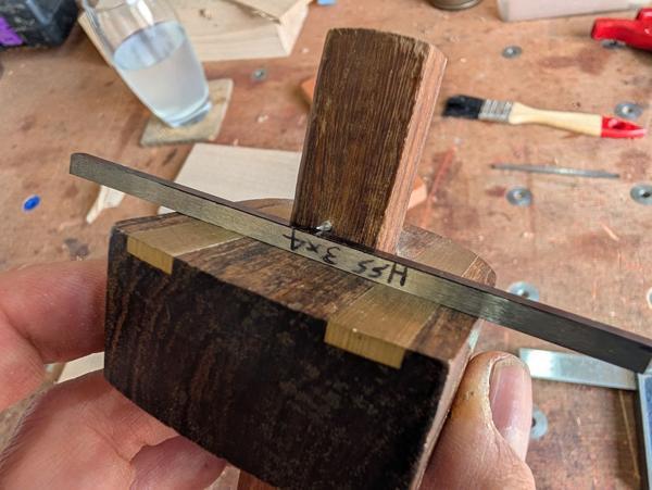
2026-08-02-06-setting-marking-gauge-oversize_600.jpg


The Walnut piece then got bandsawn and planed:
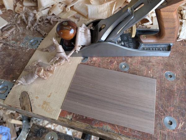
2026-08-02-07-more-planing_600.jpg


After getting it to the gauge line, I offered up the blade and made sure that there was a tiny ledge between blade and wood. It felt like quite a big ledge, so I planed it down a bit more until it was just a little thicker than the 4 mm blade.

With all the face planing done and the walnut piece sawn in half, I was left with this lot:
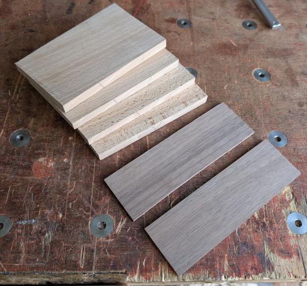
2026-08-02-08-wooden-bits_600.jpg


I sawed off a bit of excess:

2026-08-02-09-sawing-excess-off_600.jpg


Then used my favourite marking gauge and my recently made marking knife to mark an offset from the top on both the walnut piece and the 12 mm thick bit of beech:
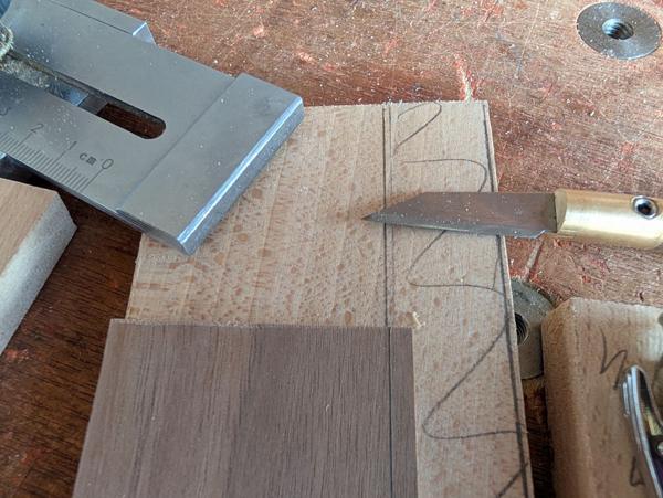
2026-08-02-10-marking-depth_600.jpg


If I did this again, I think I'd leave this step until after fitting some panel pins for alignment (described in the next post) but I think it worked okay this way.

I now needed to add a rebate in the 12 mm thick beech piece. This rebate needs to be parallel with the top face of the beech and of consistent depth: the depth of the rebate defines the offset of the groove (i.e. the distance from the groove to the edge of the board or, in normal plough plane terms, the distance from fence to cutter).

I started this rebate off with the #78 rebate plane, running it against a clamped block rather than using the fence as the grain direction suited that better:
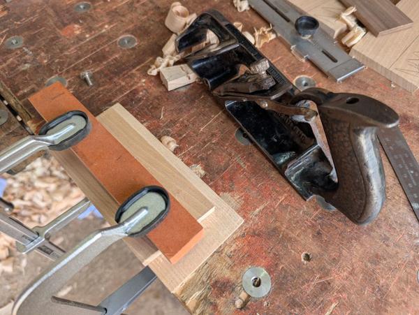
2026-08-02-11-rebate-plane_600.jpg


To ensure a nice parallel face with the two 12 mm pieces having identical fence offsets, I used a router plane to finish it off:
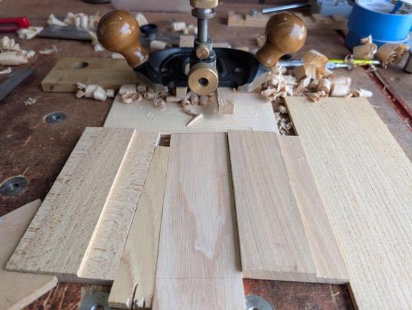
2026-08-02-12-router-plane_600.jpg


I also need a rebate on the end of the walnut pieces. This is something I'd wished I'd done when I made the other grooving planes. I made the rebate with two passes (on each side) with the rebate plane:
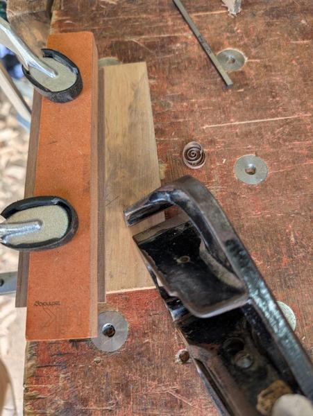
2026-08-02-13-rebate-plane-walnut_600.jpg


The rebates are there to make the part of the walnut that goes into the cut groove thinner than the groove itself (while the rest of the walnut is thicker than the cutter to allow the cutter to move in the slot). The width of the rebate effectively defines the depth of the groove as the walnut piece ends up about the same depth as the tip of the cutter.

To check I'd cut enough, I placed the cutter next to the walnut board and checked that I could feel a ledge, this time stepping up from the rebated walnut piece to the cutter rather than the other way round. With the rebate added to both sides of the walnut piece, the bit that sticks up is definitely thinner than the cutter.

That took longer to explain than it did to do!
 
Looks good - more of your "work out how to make it from first principles" approach, which always seems to pay off.

And (even as someone who has a 55) I can be confident that your own planes will continue to get used for jobs that, in theory, the 55 could do.

I can't remember what it was called or who it was by, but I do remember reading a popular science book a few years ago, exploring the difference between the unfathomable possibilities and complexities of a PC or smartphone with the simplicity of a single-purpose appliance, like a camera, alarm clock, record player, or notebook. I think the conclusion was that many people enjoy appliances more :giggle:
 
And (even as someone who has a 55) I can be confident that your own planes will continue to get used for jobs that, in theory, the 55 could do.
I can certainly imagine them being used a lot more than the #55!

At the moment I'd say that if I put the plough planes into order of most frequent use it'd come out as:

1. Rapier #43 (usually with a 4 mm cutter)
2. Pair of 5 mm (width, depth and offset) home-made planes
3. Stanley #45
4. Pair of 3 mm (width, depth and offset) home-made planes

Long gap and then...

5. Stanley #55
6. Stanley #50

Now that I've made the 4 mm ones I think they'll usurp the 5 mm ones spot and it'll be either the #43 or the new 4 mm ones in the top place and then probably the #45, followed by the 3 and 5 mm home-made ones.

For a while I used the 3 mm planes loads but I've tended to make the bases of boxes and drawers just a little thicker more recently (mainly just for ease of planing the slightly thicker material), hence the desire for a 4 mm set.
 
Last edited:
Looking great so far! I wouldn't mind making one of these. Seems like 99% of the time I am using one to cut grooves for drawer bottoms. Which is basically a 1/4"(6mm) same depth and distance from edge.

Would love to get a 43 but those things are super rare over here.
 
Last edited:
Looking great so far! I wouldn't mind making one of these. Seems like 99% of the time I am using one to cut grooves for drawer bottoms. Which is basically a 1/4"(6mm) same depth and distance from edge.

Yeah, that's exactly the principle behind the idea. If you're using the same dimensions over and over again, why not have a dedicated plane. These are really easy to make: it took me two days like the title says and I don't think they were particularly "full-on" days, just pottering at it when I felt like it.

Would love to get a 43 but those things are super rare over here.

I'm surprised at that: I thought old metal bodied planes in general were more common over there than here.
 
Yeah, that's exactly the principle behind the idea. If you're using the same dimensions over and over again, why not have a dedicated plane. These are really easy to make: it took me two days like the title says and I don't think they were particularly "full-on" days, just pottering at it when I felt like it.


I'm surprised at that: I thought old metal bodied planes in general were more common over there than here.
Well, you can find a Stanley 4 or 5 on every street corner. Even 3s, 7s and 8s are pretty easy. The joinery planes less plentiful. But for some reason the Record 43 seems to be very rare here, possibly only people that brought them over from the UK? Anytime i see them on ebay for the past 6-7 years its always in UK and shipping costs as much as the plane
 
I have a lot of drawers to make soon. I just might make one. I just need to work out the sizes of the groove etc. Food for thought.
 
Well, you can find a Stanley 4 or 5 on every street corner. Even 3s, 7s and 8s are pretty easy. The joinery planes less plentiful. But for some reason the Record 43 seems to be very rare here, possibly only people that brought them over from the UK? Anytime i see them on ebay for the past 6-7 years its always in UK and shipping costs as much as the plane
Maybe you'll have to find one of the members on here that goes back and forth between the UK and US quite regularly and talk nicely to them :ROFLMAO:
 
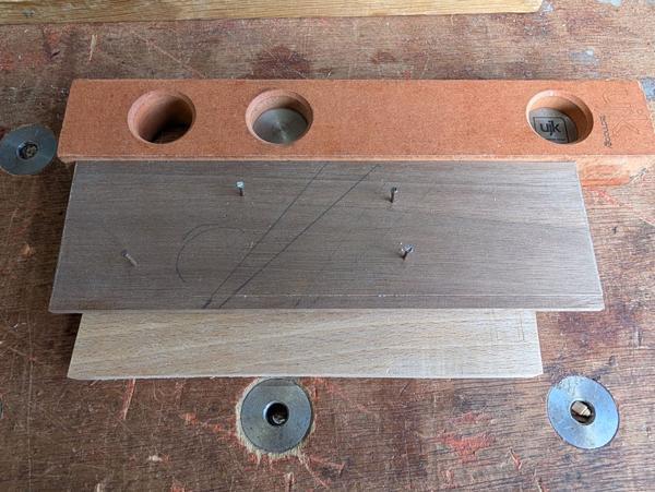
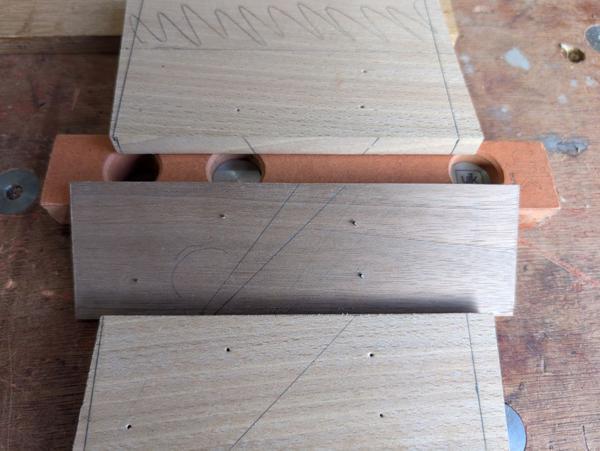
Next up was a step I probably should have done earlier in the process. I placed the walnut on top of the thicker bit of beech and tapped some short panel pins into it:

2026-08-07-01-panel-pins_600.jpg


In that photo you can see the shape of the opening for the blade and a rough idea of where the hole (for shavings to escape) will go. On the previous grooving planes I made the wedge 10°. This time I thought I'd try 8°, although I didn't have a particularly good reason for that.

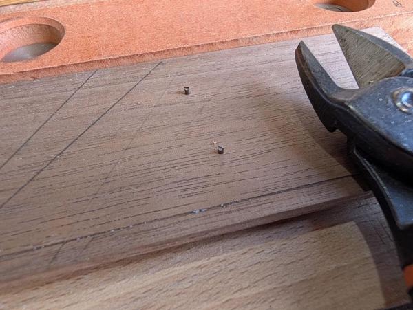
The pins then got snipped off...

2026-08-07-02-snipped-off_600.jpg


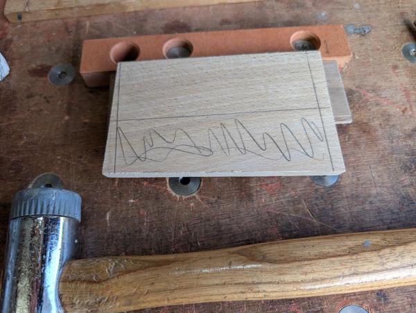
... and then the outer piece (which has yet to be cut down) was tapped onto the ends of the pins:

2026-08-07-03-outer-piece-tapped-on_600.jpg


After taking it apart, I was left with little dents in the beech pieces:

2026-08-07-04-dents_600.jpg


The cut-off panel pins being stuck in the walnut piece does make it slightly more awkward to work with but it's manageable.

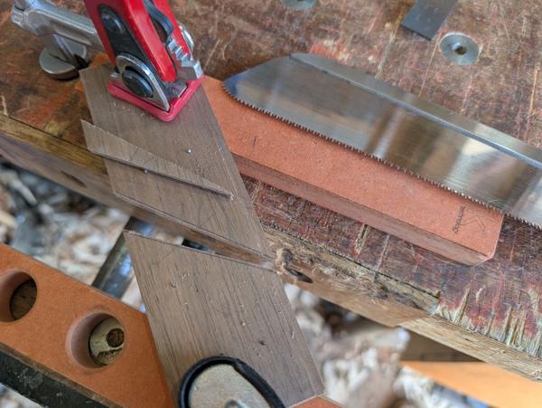
The opening for the blade got cut out with a Dozuki:

2026-08-07-05-sawing-opening_600.jpg


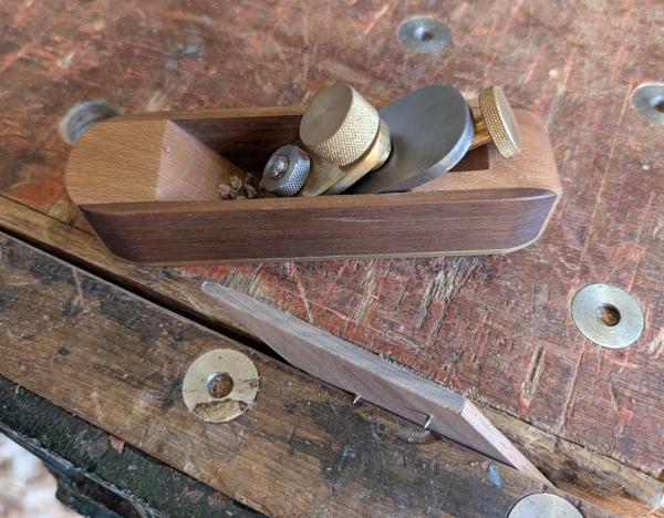
The ends got planed down to the knifed lines with my home-made block plane:

2026-08-07-06-planing-ends_600.jpg


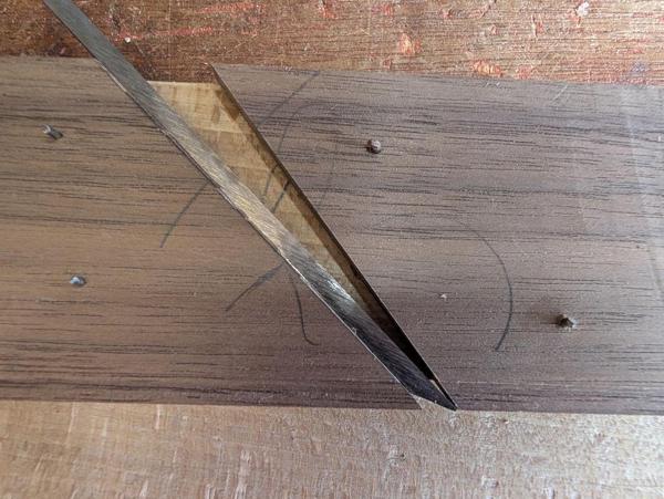
Test fit with the sharp blade:

2026-08-07-07-test-fit_600.jpg


Note that it'll be fairly easy to open up the mouth if necessary later by paring away a little bit of the protruding walnut.

Ideally, the wedge would be made out of the same bit of planed walnut as the inner piece, with just a couple of extra plane shavings taken off to make sure it's a nice sliding fit. However, the walnut off-cut I used wasn't big enough so I just grabbed another bit, chopped a bit off with a Dozuki and planed it down to the right thickness with the #4½:

2026-08-07-08-planing-wedge-wood_600.jpg


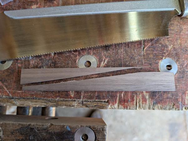
After marking an 8° angle on, I sawed the wedge in two with a Dozuki...

2026-08-07-09-split-wedge_600.jpg


... before running the sawn edge over an inverted plane in order to clean up the surface.

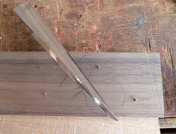
Test fit of one half...

2026-08-07-10-wedge-test_600.jpg


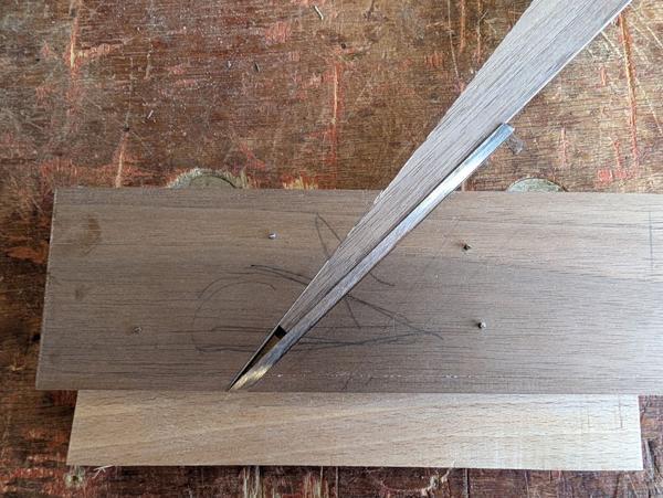
and the other (using the same blade as I only have one prepared at the moment)...

2026-08-07-11-wedge-test-2_600.jpg


The outer pieces (the 10 mm thick beech bits) got sawn to size and had their edges planed down to the line:

2026-08-07-12-outer-pieces_600.jpg


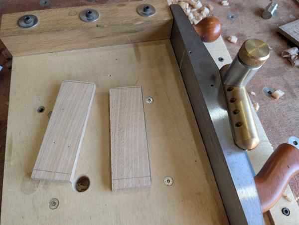
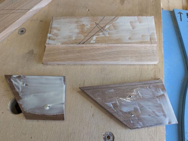
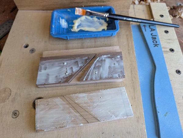
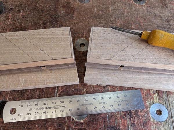
After drawing pencil lines on both beech pieces showing the location of the opening, I applied some glue, keeping clear of the rebate on the walnut piece and the opening on the beech piece:

2026-08-07-13-glue-1_600.jpg


After pressing the walnut pieces into place, I applied more glue...

2026-08-07-14-glue-2_600.jpg


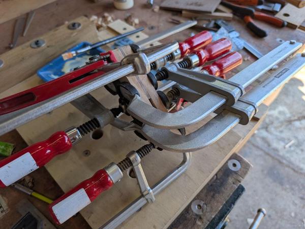
... and then put a slightly ridiculous number of clamps on:

2026-08-07-15-excessive-clamps_600.jpg
 
While the glue was drying, I got on with the other blade. When I made the first set of grooving planes, I made the blades out of gauge plate (aka O1 tool steel). That means they're very easy to shape (as the steel is relatively soft) but they need hardening and tempering (which is quite simple with such a small blade).

If memory serves me correctly, I started with a relatively wide piece of gauge plate, used the bandsaw to get them down to slightly over the right width for the cutter, then used the milling machine to bring to size. A hand file was used to add the slight taper on the sides and then I hardened and tempered them before sharpening.

This time, I'm starting with a bit of 3 × 4 mm high-speed steel. That means none of the hardening and tempering is required and, since it's already the right width (4 mm) I don't need to do any dimensioning either. What I do need to do is to add a slight taper on the sides and grind the profile on the end.

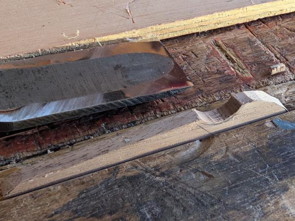
The taper on the sides changes the rectangular cross-section of the cutter into a trapezium, with it narrower further away from the cutting edge. This gives some clearance behind the cutting edge and means the cutter scrapes the side of the groove rather than rubbing on it. Without the taper you tend to get lots of tear-out on the groove walls.

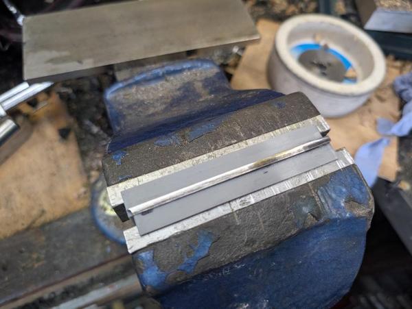
On the first blade (the one I've been showing in the earlier posts), I did this with some little 3D-printed jaw liners (made with a slight angle) to allow me to hold the blade at an angle in the bench vice so I could rub a diamond plate horizontally over the top:

2026-08-07-16-vice-jaws_600.jpg


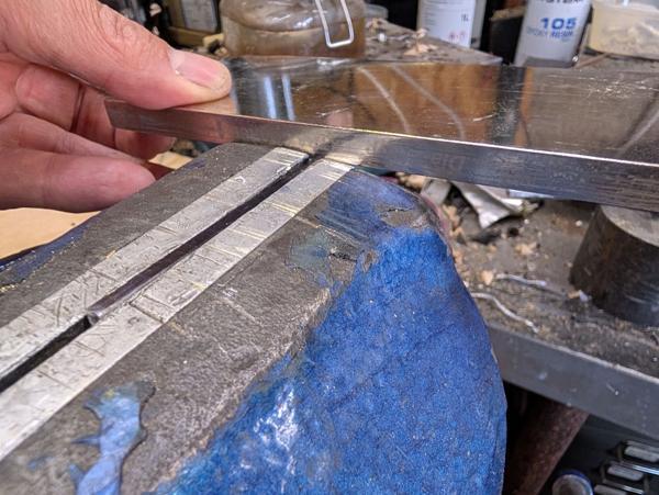
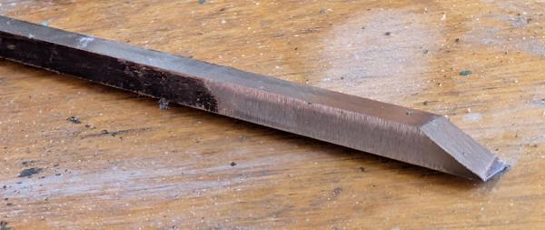
That was quite tedious (high-speed steel is hard!) so for the second blade I decided to do it a different way. The taper is only needed near the cutting edge, so instead of trying to grind away the blade all the way along, I held it in the bench vice with a bit sticking out and attacked it with the coarse diamond plate held at a slight (but arbitrary) angle:

2026-08-07-17-rubbing-with-diamond-plate_600.jpg


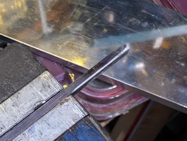
After a few strokes it looked like this (the marker pen helps me see where I've ground and where I haven't):

2026-08-07-18-fair-way-to-go_600.jpg


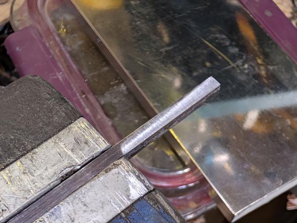
After a little bit more work it looked like this:

2026-08-07-19-that-will-do_600.jpg


I then flipped it over and did the other side, being careful to make sure the angle resulted in a trapezium and not a parallelogram!

Once both sides were done, it could be ground and sharpened. I went with the angle that the bench grinder's table was already set up for because I was lazy, but any angle less than about 40° should be fine.

2026-08-07-20-ground-and-sharpened_600.jpg


With the second blade prepared, I took the bodies out of the clamps and marked up a location for the hole that will allow shavings to escape:

2026-08-07-21-awl-for-hole-centre_600.jpg


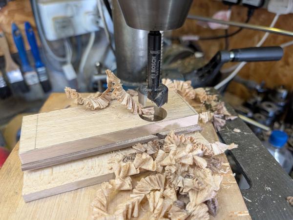
It needs to be fairly close to the bottom and the bed but mustn't cut into the bed or it could affect the way the blade sits. I measured 14 mm from the bottom and 14 mm from the bed position. I'm using a 25 mm Forstner bit, so I probably could have got away with 13 mm, but this was fine.

2026-08-07-22-forstner_600.jpg


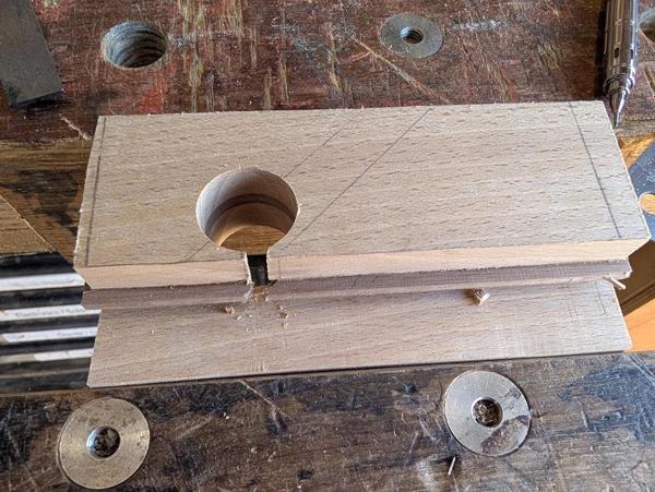
The hole then got opened out with a Dozuki:

2026-08-07-23-sawn-out-opening_600.jpg


At this point, it's a fully functional plough plane. I couldn't resist giving it a go:

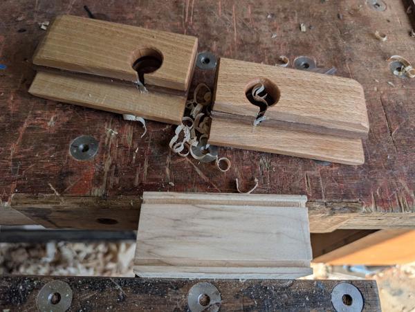
2026-08-07-24-test-groove_600.jpg


It worked!

When I made the first set, it took absolutely ages to get to the point that it was working (due to the issues with the walnut middle piece being the same thickness all the way down). The little rebate on the bottom has cured that nicely.

While it worked, it was (unsurprisingly) extremely uncomfortable to use, so it was time to get on with a bit of shaping. Everything from now on is ergonomics so nothing is too critical really.

I started by shortening the back a little with a saw and then shooting both ends to square it all up:

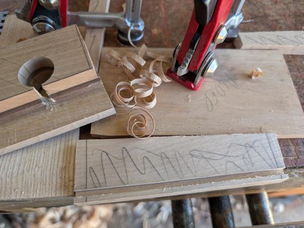
2026-08-07-25-shooting-ends_600.jpg


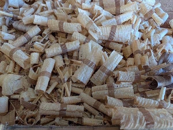
That produced some funky end-grain shavings:

2026-08-07-26-funky-shavings_600.jpg


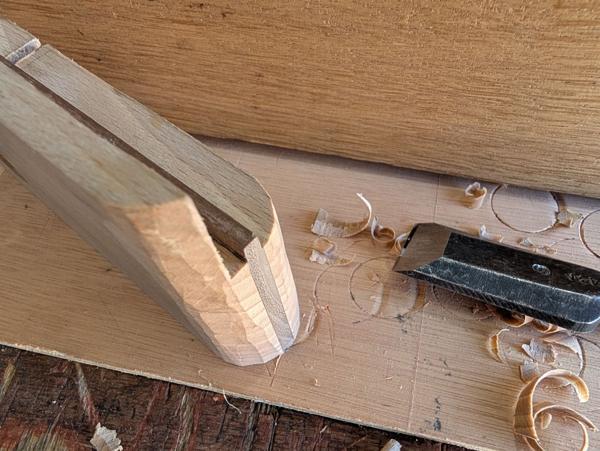
I was recently given a set of Japanese chisels by an astonishingly generous member of the MIG welding forum, so I decided to put one of them to use for shaping the backs of the planes. Work-in-progress shot:

2026-08-07-27-shaping-with-japanese-chisel_600.jpg


When I did that on the first set of grooving planes I used a round-over bit in the screaming monster (electric router). Doing it with a chisel is a far more pleasant experience.

Once the back was rounded over, I did a lot more in the way of chamfering and rounding over with my little block plane:

2026-08-07-28-shaping-with-block-plane_600.jpg


The wedge got shaped mostly by chisel, with the finger indent roughly shaped with the chisel bevel-down:

2026-08-07-29-bevel-up_600.jpg


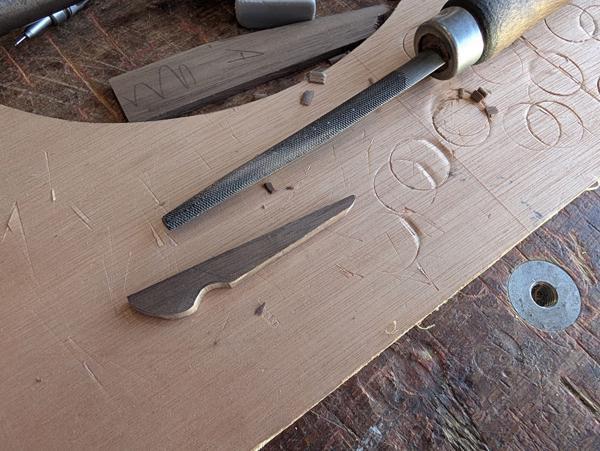
My curvy thing chisel skills are somewhat lacking, so I finished the shaping with a half-round file:

2026-08-07-30-half-round_600.jpg


I also used the half-round file to round over the Forstner hole openings. I'd love to be able to do this sort of thing with chisels but I need to practise on some scrap pieces rather than something that's nearly finished!

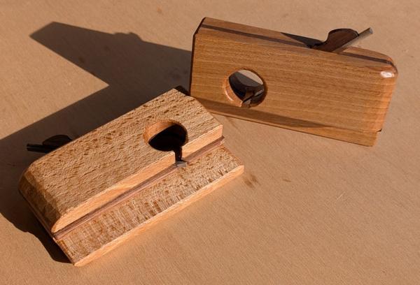
With that done, the planes were essentially complete: they just needed a few coats of Mike's Magic Mix to protect them:

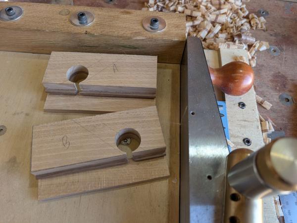
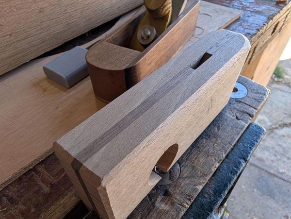
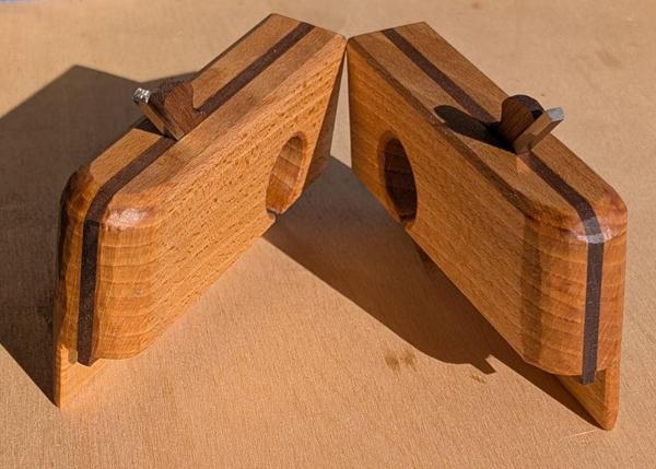
2026-08-09-01-two-new-planes_600.jpg


2026-08-09-02-standing-up_600.jpg


It would seem wrong not to finish with a quick test:

2026-08-09-03-test_600.jpg
 
Last edited:
Awesome job, they look great. As for the trapezium shape. I have a mortise chisel that is trapezium shaped, as well as one that is a perfect rectangle. To add more options, my Japanese mortise chisel is trapezoidal butt he sides are rounded comcave. When trying to figure out which way it was supposed to be i found differing arguments for both. Checking my cutters for my Stanley 50 they are all trapezoid
 
Awesome job, they look great. As for the trapezium shape. I have a mortise chisel that is trapezium shaped, as well as one that is a perfect rectangle. To add more options, my Japanese mortise chisel is trapezoidal butt he sides are rounded comcave. When trying to figure out which way it was supposed to be i found differing arguments for both. Checking my cutters for my Stanley 50 they are all trapezoid
I don't think I've ever checked what shape my mortice chisels are, but I guess with the fact they "walk" along the slot as they go in then a trapezoid shape makes sense.

I think it's pretty much essential for plough plane cutters. When I first made some blades for one of my Stanley plough planes I didn't know about the relief on the sides & the blades made a real mess of the groove walls.
 
I don't think I've ever checked what shape my mortice chisels are, but I guess with the fact they "walk" along the slot as they go in then a trapezoid shape makes sense.

I think it's pretty much essential for plough plane cutters. When I first made some blades for one of my Stanley plough planes I didn't know about the relief on the sides & the blades made a real mess of the groove walls.
Yeah i was a little confused on terminology etc. I saw some mortise chisels labeled “registered” mortise chisels. I bought an old vintage British mortise chisel and noticed it seemed to bind up in the mortise as it got deeper. Thats when i noticed the sides were parallel compared to my other one. Trying to research I found some places say it should be a trapezoid, Rob Cosman swears by having the sides parallel, and all the ones he sells are perfectly rectangular to a tight tolerance.
 
Last edited:
Yeah i was a little confused on terminology etc. I saw some mortise chisels labeled “registered” mortise chisels. I bought an old vintage British mortise chisel and noticed it seemed to bind up in the mortise as it got deeper. Thats when i noticed the sides were parallel compared to my other one. Trying to research I found some places say it should be a trapezoid, Rob Cosman swears by having the sides parallel, and all the ones he sells are perfectly rectangular to a tight tolerance.
I wonder if that's another thing (like sharpening) that starts religious wars :ROFLMAO:

My gut feel is that for the way I chop mortices it probably doesn't matter much but a trapezoidal shape probably makes it a little easier. Note that I still haven't checked what shape my mortice chisels are!

However I know some people thoroughly disapprove of the way I chop mortices (chop them under-width and then pare the walls). The only argument I've heard against doing it the way I do is that chopping to size is quicker, but I don't think that's true. The actual chopping process is a little quicker if I don't have to worry about the squareness of the chisel and the extra step of paring makes up the difference such that they take about the same overall time in my opinion. This is the same argument I have for honing guides: putting the blade in the honing guide takes 15 seconds, but I can move the blade on the stone far faster in the honing guide than without it so the actual sharpening time is quicker and overall it really doesn't make much difference either way.

Probably best not to poke that tiger too much though: both of the above opinions seem to wind some people up!
 
Another great project, Al. Well done. I'm rather envious of your nonchalance with metal working, as always.

How easy are they to adjust, and do they keep their setting well?
 
Another great project, Al. Well done. I'm rather envious of your nonchalance with metal working, as always.

Thanks Mike

How easy are they to adjust, and do they keep their setting well?
They keep their setting very well and on the 3 & 5 mm ones at least the blades seem to stay sharp for ages so I haven't sharpened & re-set them many times; hopefully the same will be true of the new ones.

Adjusting is just like any other wooden plane really: hammer taps on the blade to extend & on the back to retract. The 8° angle on the new wedges does make it slightly harder to set the wedge than it was with the 10° ones (just because it is narrower at the wide end so there's less to hit). I settled on resting the wedge on the edge of the bench & tapping the plane with a mallet rather than resting the plane & tapping the wedge.
 
Ok Al, here's an idea to think about. You could extend the usefulness of your nice grooving planes by making tonguing planes to go with them. Different sizes to suit thicker or thinner boards.

This is the sort of thing I mean:

IMG_20260810_090004450.jpg
IMG_20260810_090032417.jpg
 
That's an interesting idea. The blades would be much more complicated (but entirely possible with a milling machine :)). Making them would be quite straightforward if I went with the same construction technique I think.

I might wait until I have a plausible use for them though. My #45 has tongue and groove blades but I've yet to use them.
 
Ok Al, here's an idea to think about. You could extend the usefulness of your nice grooving planes by making tonguing planes to go with them. Different sizes to suit thicker or thinner boards.
How well do the tonguing planes work ? I don't have any woodie versions of those. I do have a couple of tonguing cutters for the #050C, and they do not work well enough to bother with. I used a mortice gauge and a woodie rebate plane instead. I expect the poor performance of the 050C cutters is down to the lack of a proper sole, so I'm guessing the wooden versions are much better ?
 
I'm fortunate enough to have a #55 and I think that's the one I would grab if I were going to have a go at cutting a tongue. It has the advantage of two fences so you can stick one on either side of the board and then there's no chance of meandering. Thinking about it again, I'd probably use the #45 (as it's simpler to set up) but nick the second fence of the #55 so I'd get that benefit :)
 
How well do the tonguing planes work ? I don't have any woodie versions of those. I do have a couple of tonguing cutters for the #050C, and they do not work well enough to bother with. I used a mortice gauge and a woodie rebate plane instead. I expect the poor performance of the 050C cutters is down to the lack of a proper sole, so I'm guessing the wooden versions are much better ?
I had a matched pair of 1/2” tongue and groove planes. I also had one of the wooden “coming and going” t&g planes. I ended up selling them all to get the Stanley 48 and 49. I would say in order of most to least i liked the #1 matched pair, #2 Stanley 48 & 49, #3 the coming and going version(didn’t like this one at all). The wooden matched pair seemed to slide effortlessly across the wood. The metal ones work ok but a little “fiddly”. From researching them all, people that have used them all seem to prefer the metal version of the “coming and going” plane with the opposing handles. I forget the Stanley model number but i have never actually seen them in any shops or in person
 
Last edited:
I've not really needed to use them much,but their big advantage is that there's no need to mark out the work or adjust the planes.

That is also true of the 48 and 49 of course. I had one of those (can't remember which) and used it to make a garden planter from offcuts of cedar. It did the job but the metal handle was really uncomfortable in my hands, always digging in somewhere. I gave it to a collector who was happy to get one step closer to completing his run of Stanley numbers.
 
That's an interesting idea. The blades would be much more complicated (but entirely possible with a milling machine :)). Making them would be quite straightforward if I went with the same construction technique I think.

I might wait until I have a plausible use for them though. My #45 has tongue and groove blades but I've yet to use them.
You don’t need to make a notched blade unless you want the challenge. You could just have 2 separate blades like the #48 and 49 planes.
 
You don’t need to make a notched blade unless you want the challenge. You could just have 2 separate blades like the #48 and 49 planes.
Really? You might be right, but I suspect the annoyance of knocking one iron out of adjustment whilst adjusting the other would be enough to drive you nuts.
 
Really? You might be right, but I suspect the annoyance of knocking one iron out of adjustment whilst adjusting the other would be enough to drive you nuts.
Not sure. For the wooden ones i always just used the playing card trick and shoved the wedges down and left them. I never tapped like a wooden smoother.
 
Back
Top