derekcohen
New Shoots
Time to re-visit the dining table, and move in a new direction. I have design, this time, a trestle table. The design is aimed at complimenting the (DC 09) chairs. To do this, in part the table legs must reduce clutter, which is the advantage of a trestle table ... the legs are tucked out of the way.The base is to be Jarrah, which is a particularly hard and stiff wood. I have used in in many builds, as many are aware. One of the advantages this has given me is the option of building with thinner stock. All the trestle tables I have seen come with rather chunky legs and stretchers, and this is not the aesthetic I prefer.
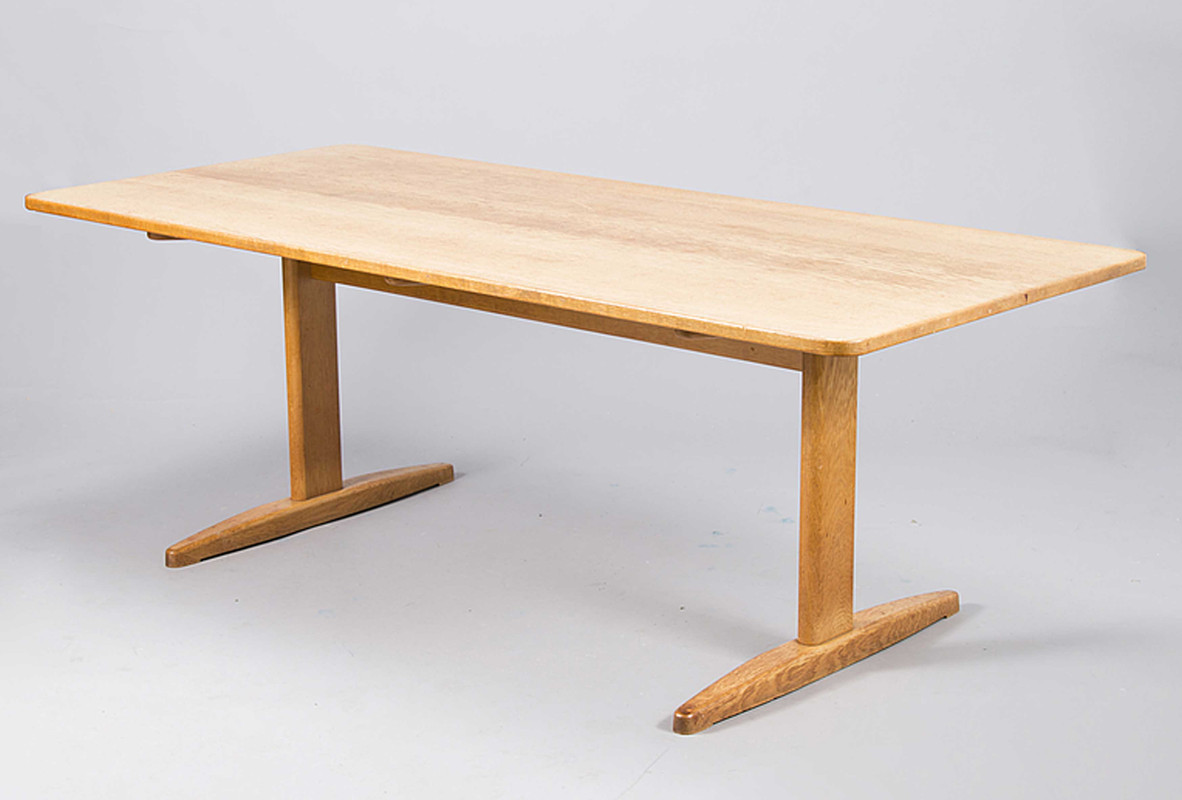
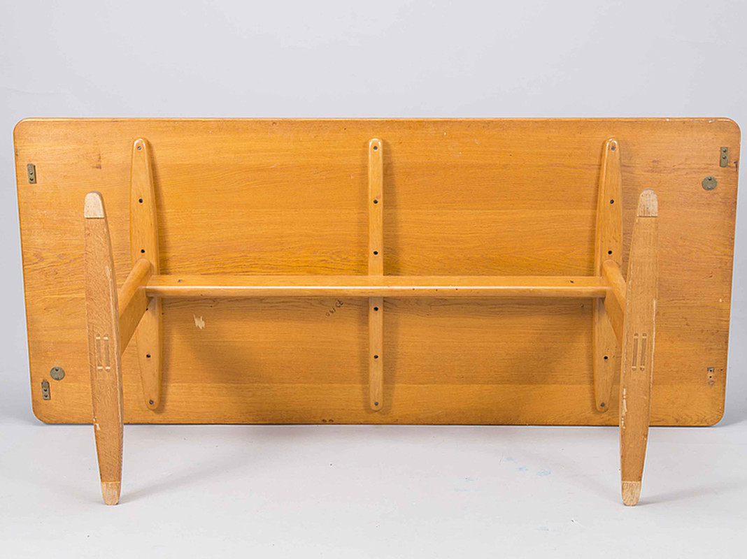
I have made up some basic drawings and plans, but nothing I want to show here. Instead, I am posting photos of tables I found which have similarities - this is just to offer up some concepts to aid in visualising what I am planning. My design is different in important areas, but there are indeed similarities ...Here is a table made by Borge-Morgensen, which has similar dimensions for the parts. The construction is very similar.
I have made up some basic drawings and plans, but nothing I want to show here. Instead, I am posting photos of tables I found which have similarities - this is just to offer up some concepts to aid in visualising what I am planning. My design is different in important areas, but there are indeed similarities ...Here is a table made by Borge-Morgensen, which has similar dimensions for the parts. The construction is very similar.
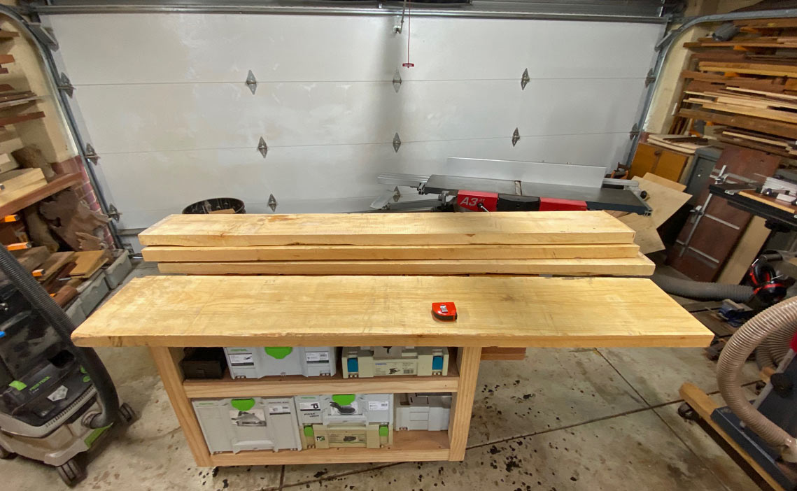
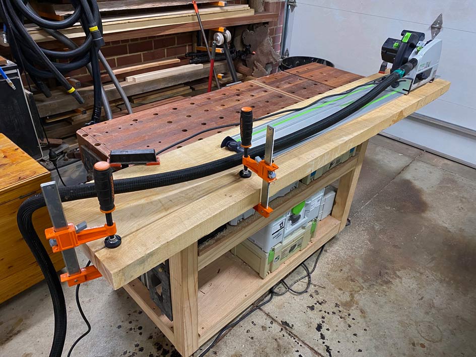
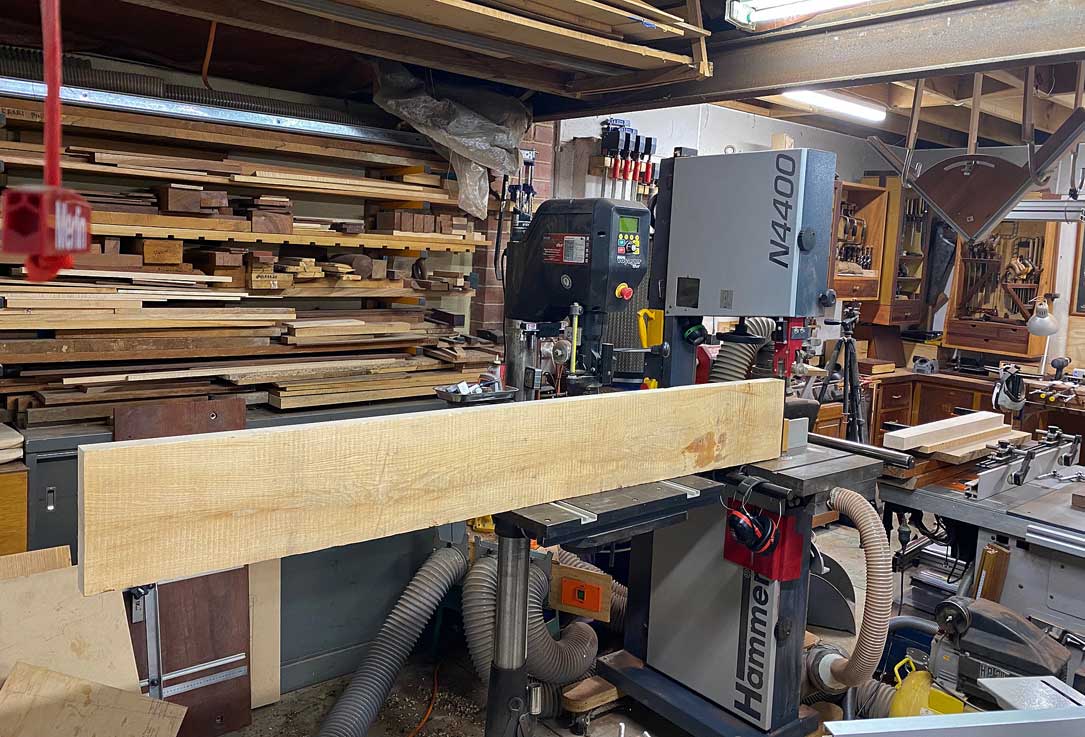
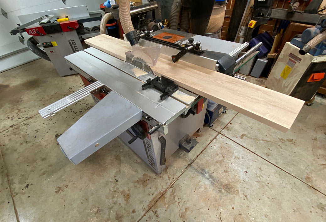
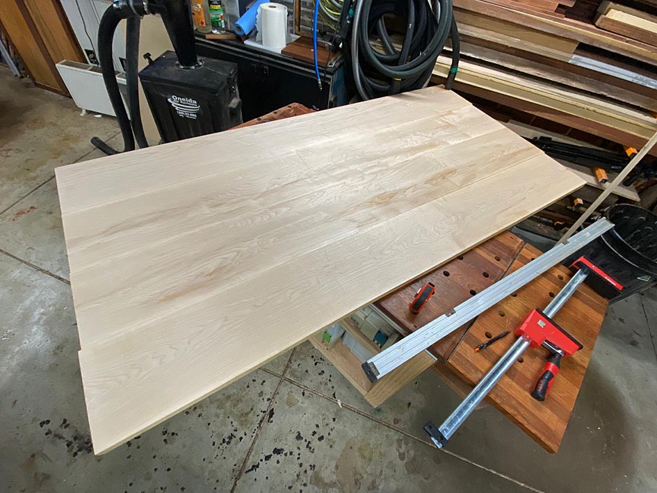
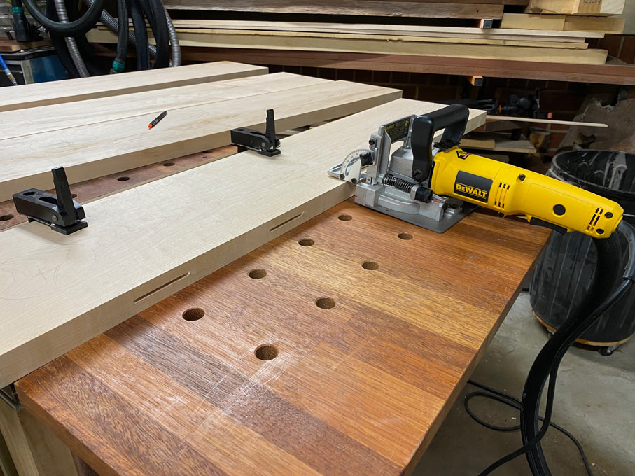
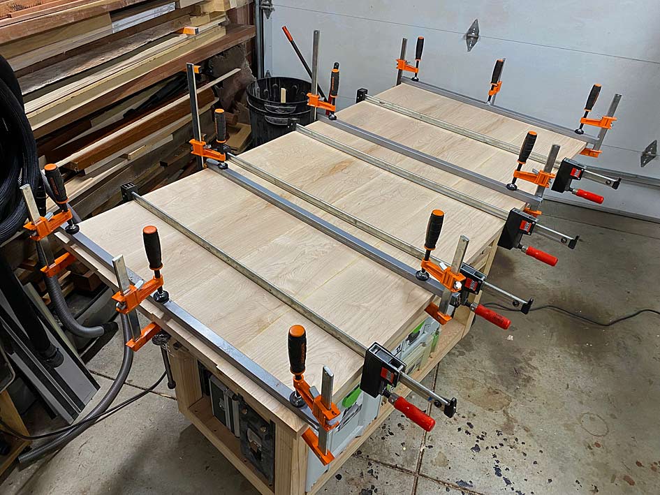
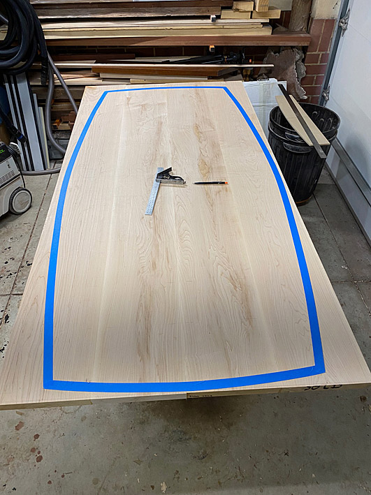
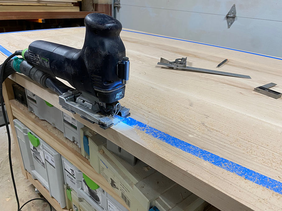
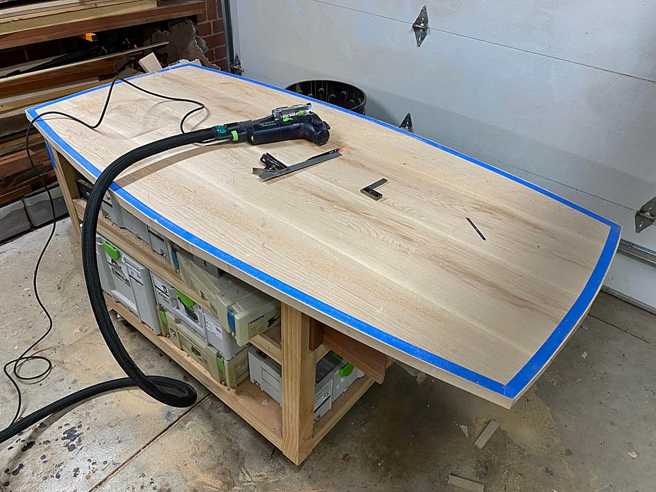
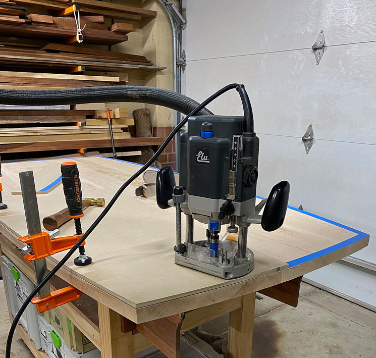
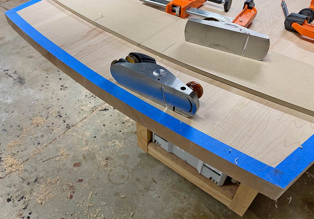
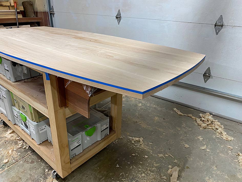
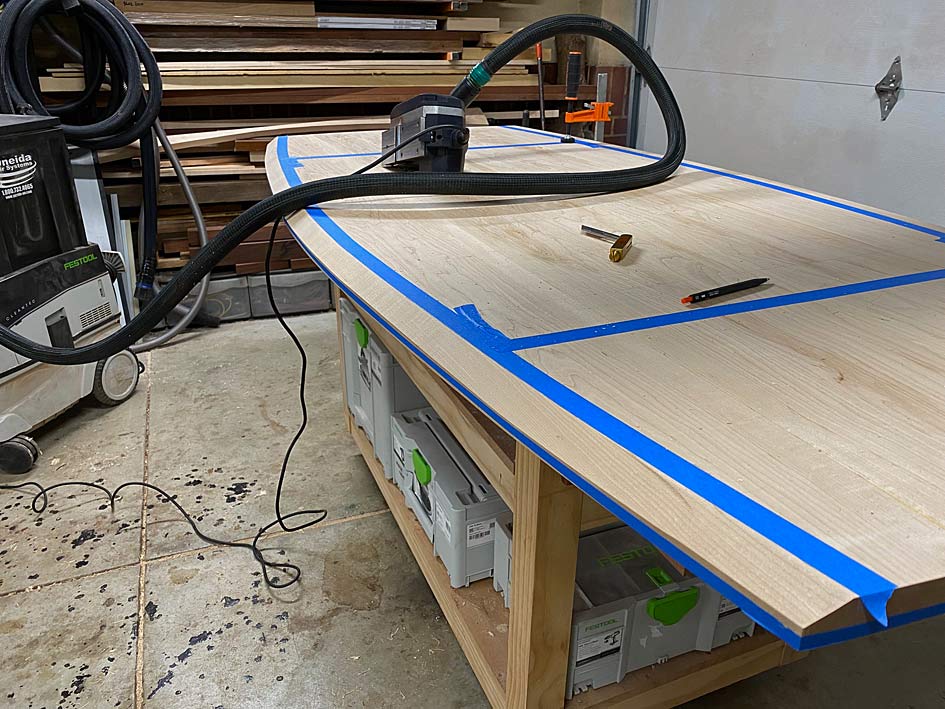
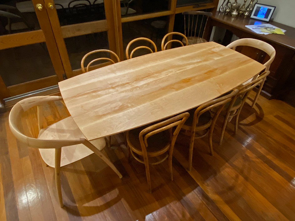
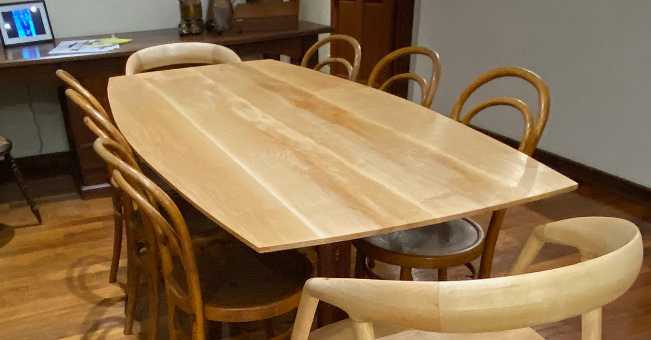
The top will be made from Rock Maple, and 1825mm long (72") x 900mm (35") wide, and 30mm thick. At present my first choice is to use a shallow elliptical router bit, creating a pillowed (very slightly rounded) face to soften the edge. This is in keeping with the chairs, which are all curvy. The second choice - if this leaves the top looking too thick - is to use a shallow undercut chamfer. Note that the top will be curved along all sides.Something like this Nakashima table ...
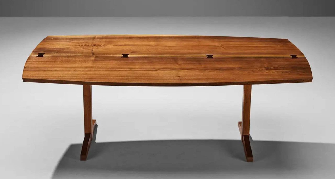
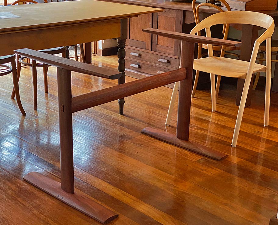
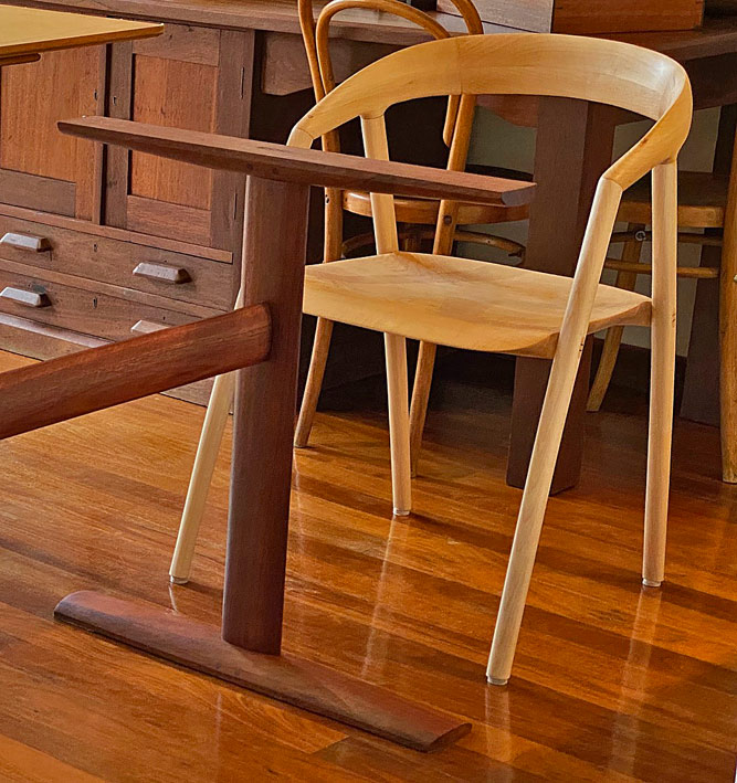
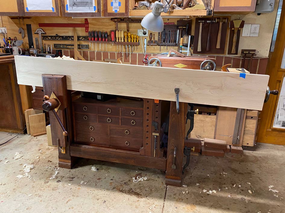
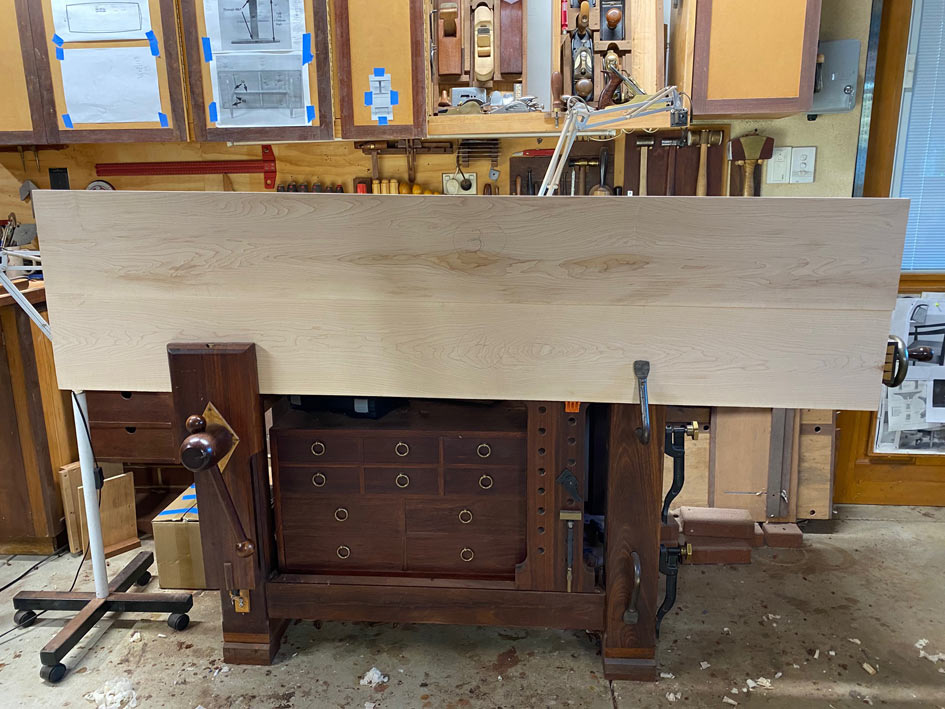
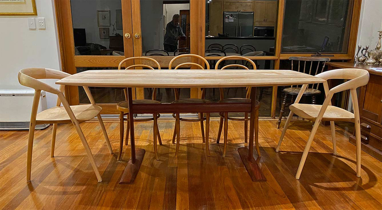
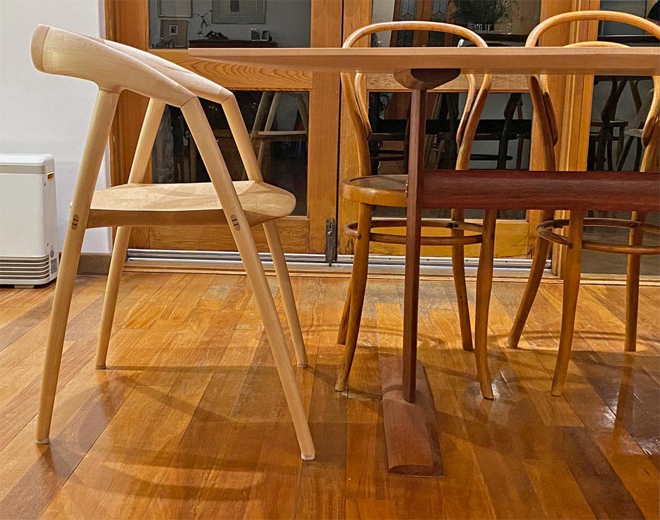
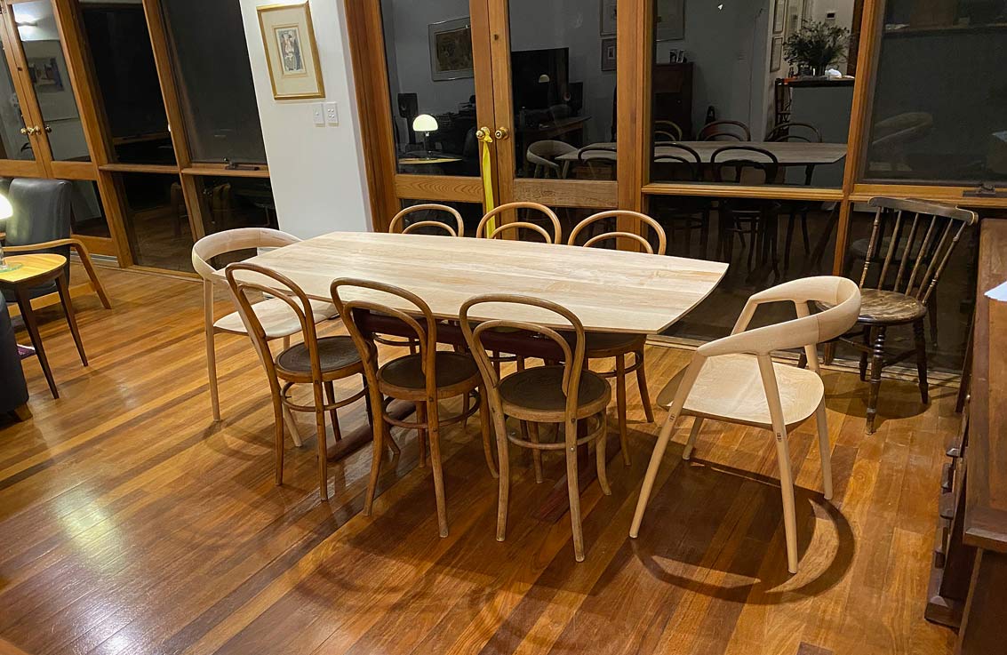
The legs link to the chairs through an oval shape I plan to give them (the legs of the chairs are oval) ... both in the horizontal and vertical parts. Joinery is pinned loose mortise-and-tenon and not the bridle joint in the Nakashima photo.The light Rock Maple top will appear to float on the dark Jarrah base. That is the intention.
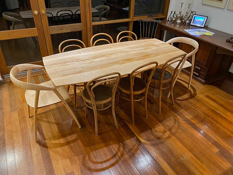
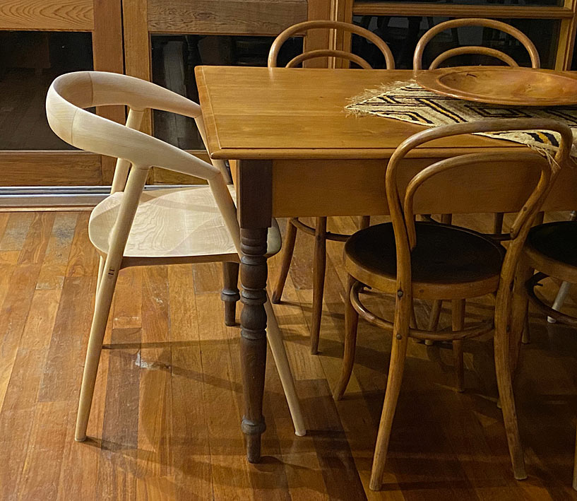
A comment about the DC 09 Chairs I built: When we were planning to build a larger table, it was necessary to add two more chairs. My initial thought was to find bentwood carvers to join the existing bent wood chairs, but we did not like their looks, and went searching for something else. Much of our furniture is contemporary, Mid Century-styled (as you may have noticed from my builds), and so I decided to add two modern carvers (we do not mind a mix-and-match), and use the table to blend all the pieces together.
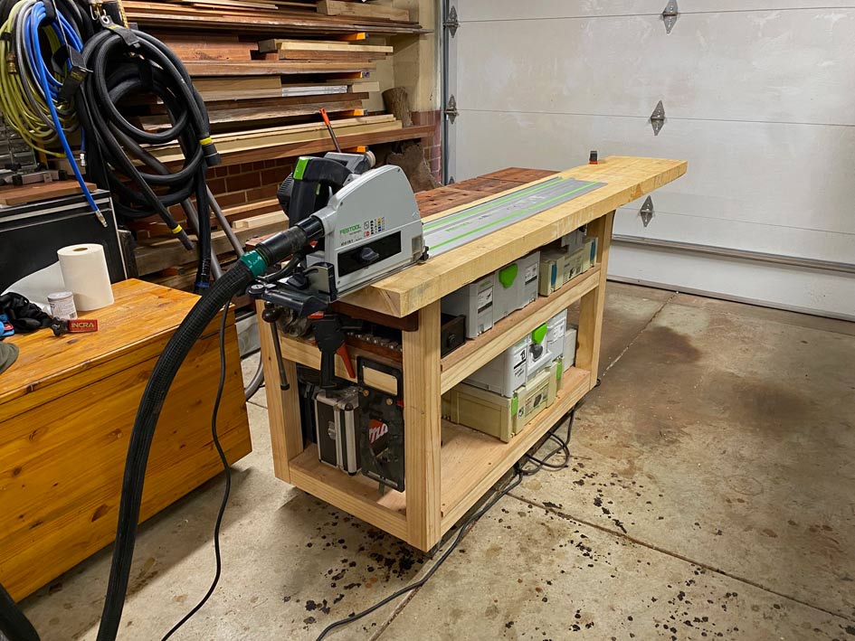
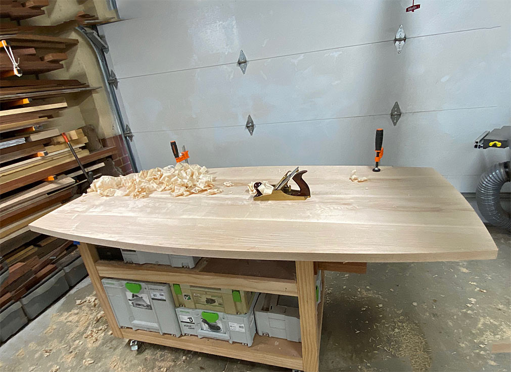
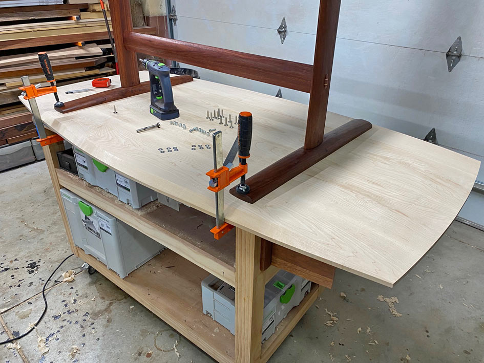
I managed to do a little work on the trestle table this weekend, in between watching the Olympic Games.
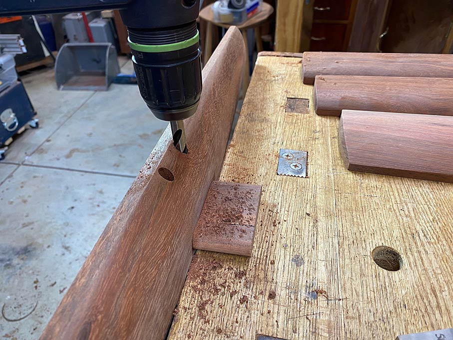
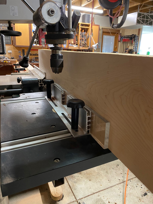
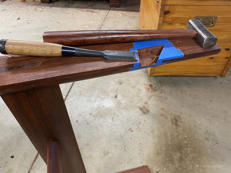
The mortise and tenon joinery is all loose tenons, which is easier to do accurately since all are through mortises. Plus I can orient the grain in the tenons for maximum strength (i.e. no run out).
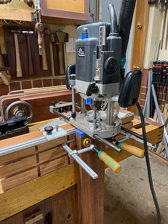
With the exception of the cross support, all mortises are 1/2" x 70mm wide x 40mm deep. The cross support mortises are 1/2" x 40mm wide x 40mm deep.
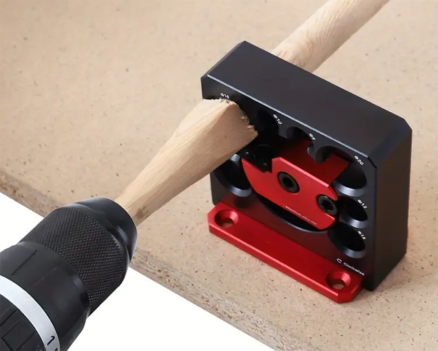
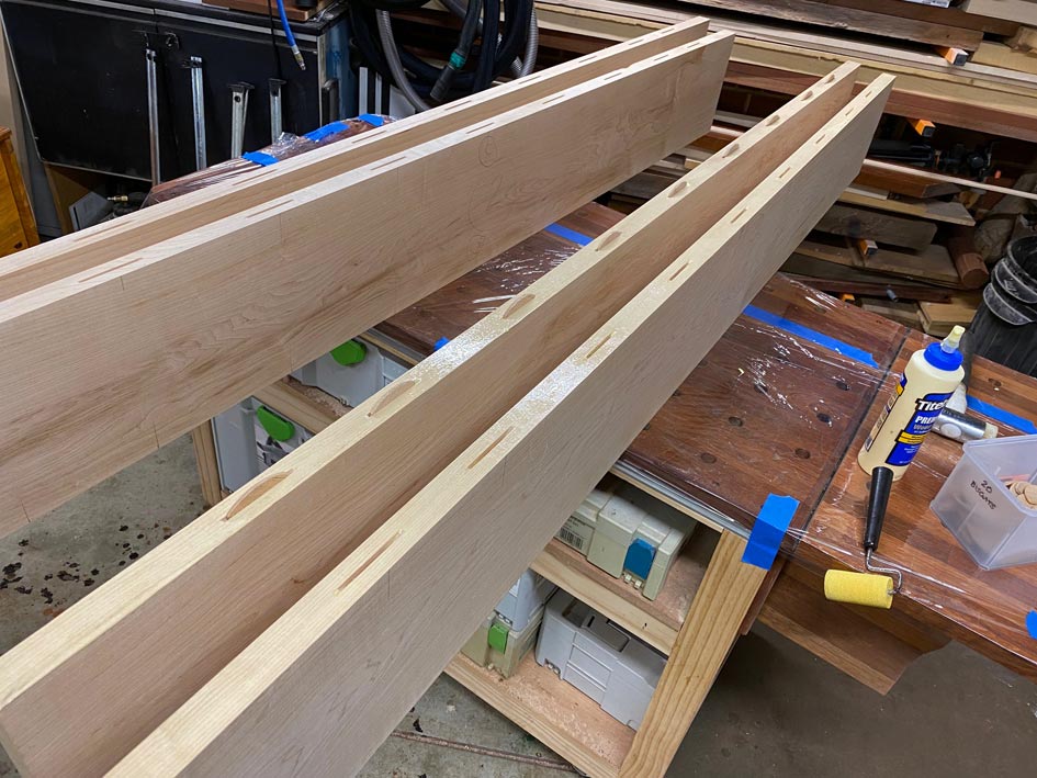
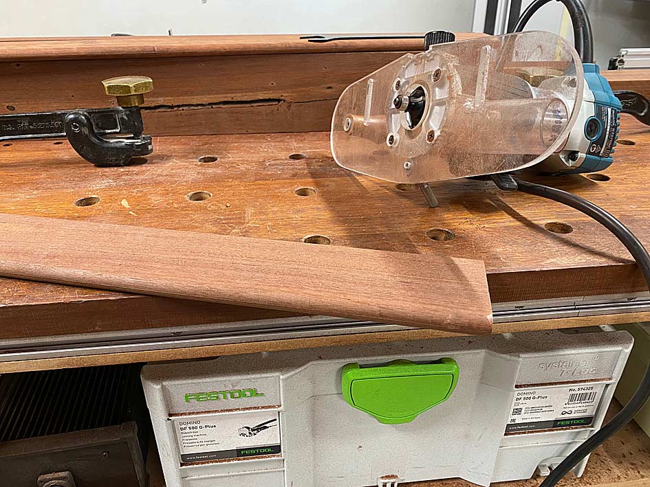
The loose tenon stock is made simply and quickly: thickness quarter sawn Jarrah, saw to width, and round over with a 1/4 round bit in a trim router.
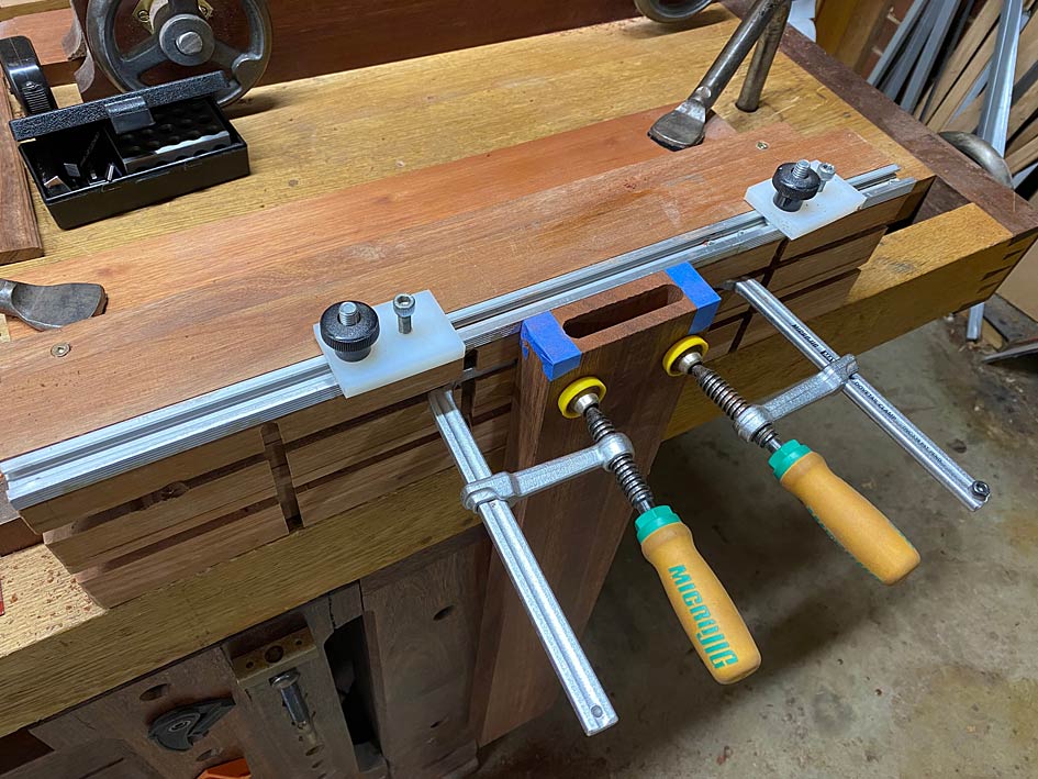
One correction for the loose tenons: the loose tenon is actually 80mm (3 1/8") long. The root is 40mm. And will be pinned at each end. That is pretty substantial. The rail will be wedged.
Regarding the choice of loose tenon joinery in this build: I have a preference for traditional mortise-and-tenon joinery. When I started making the chairs, this is what I did - integrated tenons from the seats. Then it became evident that they were vulnerable to breaking owing to run out. That is not a risk to take with chair legs. I started again, and this time used loose tenons, which allowed me to choose quarter-sawn stock.
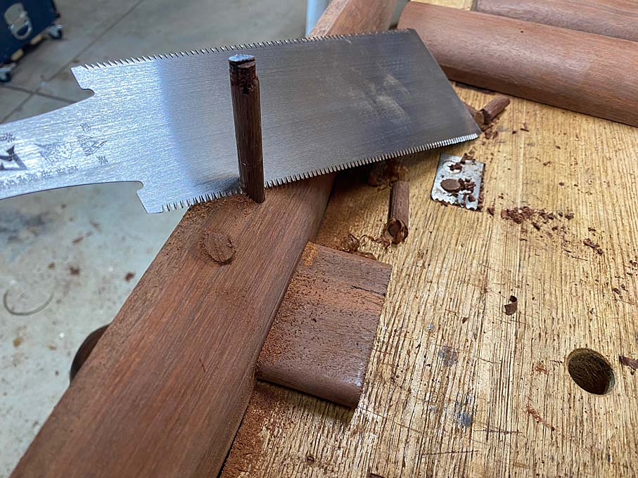
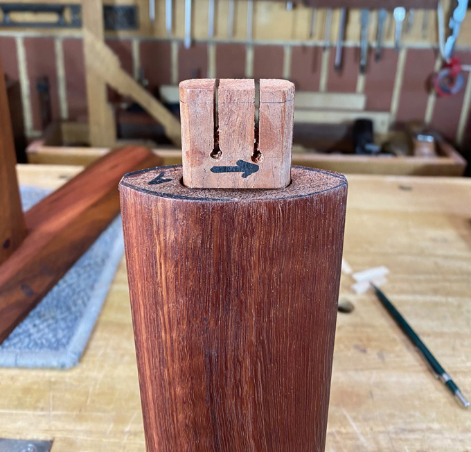
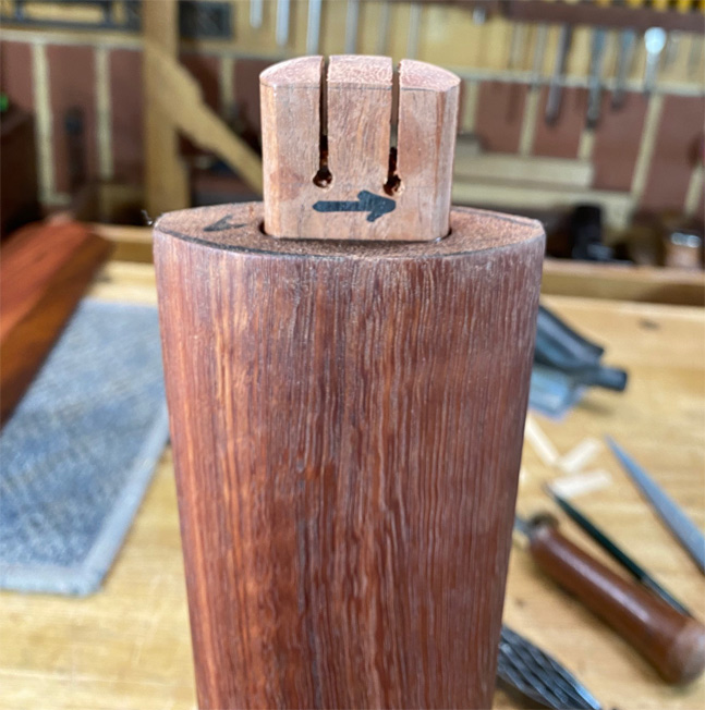
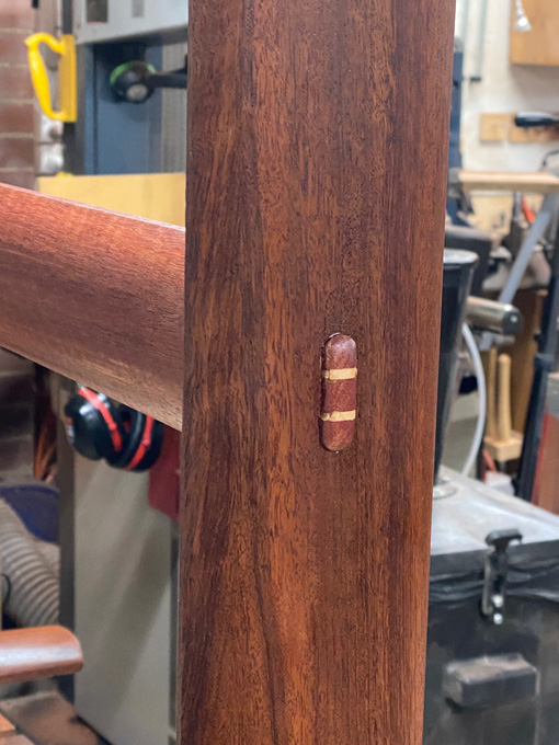
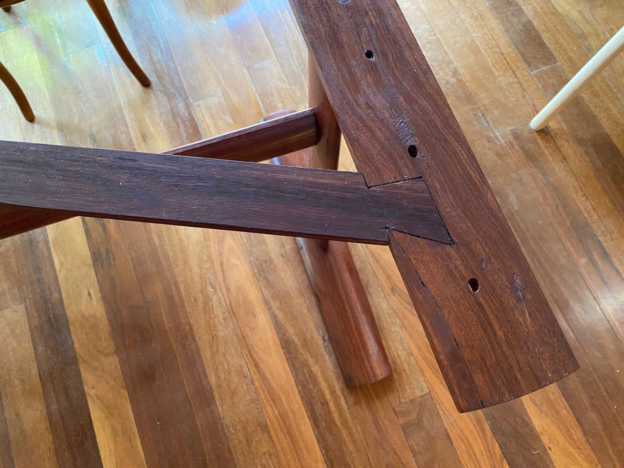
The wedged M&T legs ...

... need to be echoed in the table. Hence the round ends (made with a router) in the table legs. Also the oval table legs linking to the oval chair legs.
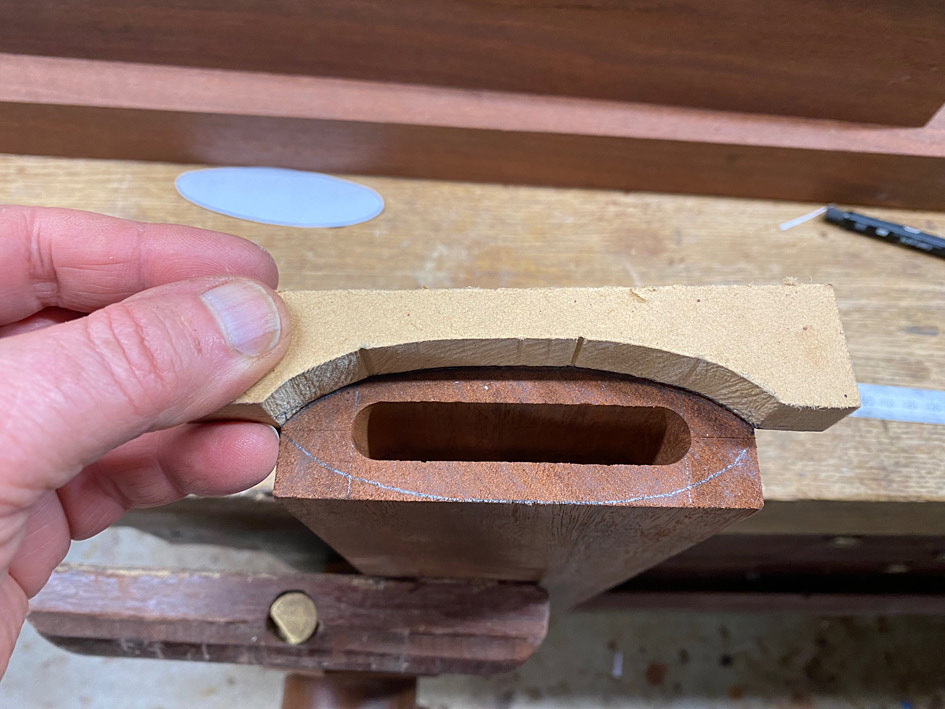
Now we get to the interesting part. What I start with will be quite different from what ends up finished. There is very little that will not be carved away. Remember, the table is intended to blend with the two chairs I built. For this reason, the two vertical sections and the horizontal cross support will be oval in cross section. I have not seen this before ...
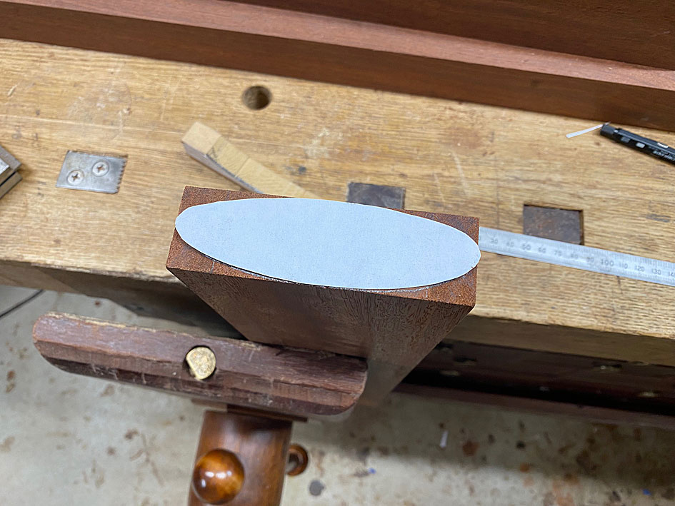
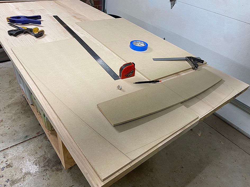
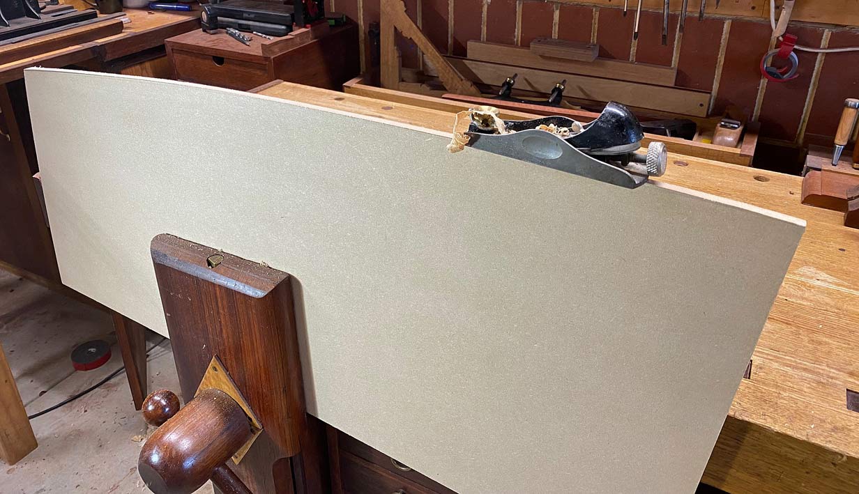
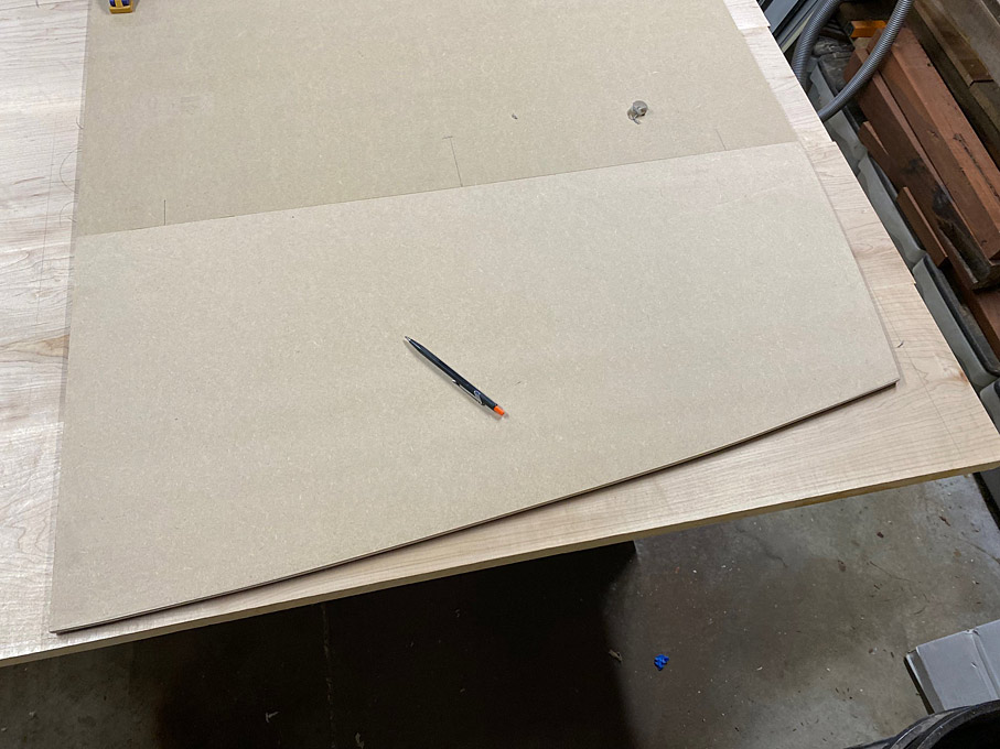
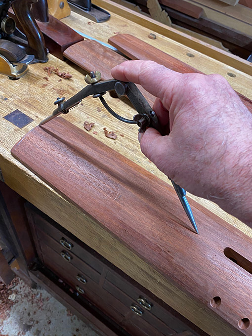
A template for later use ...
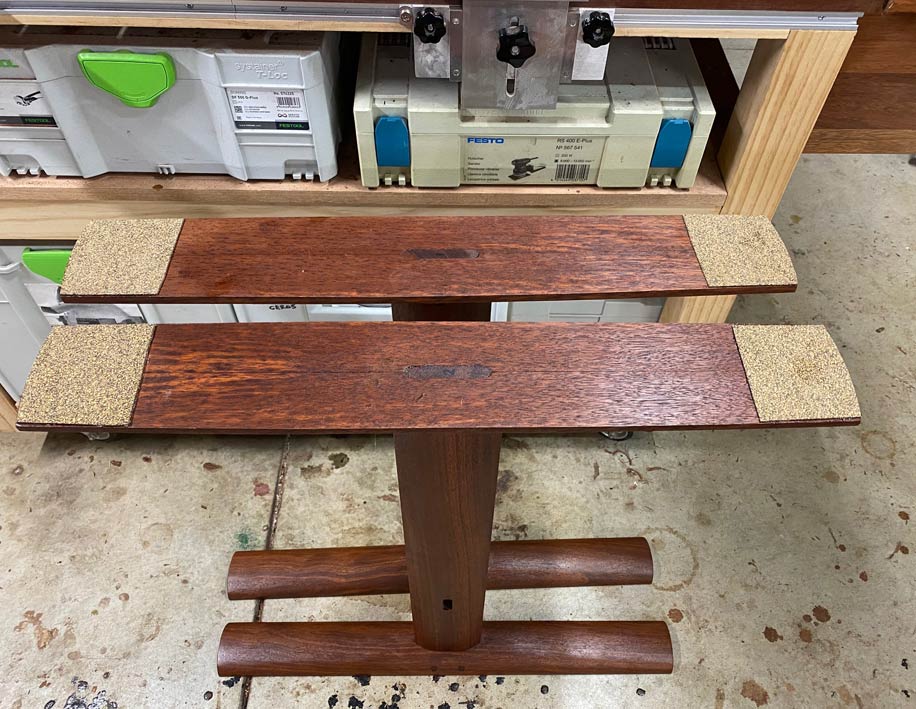
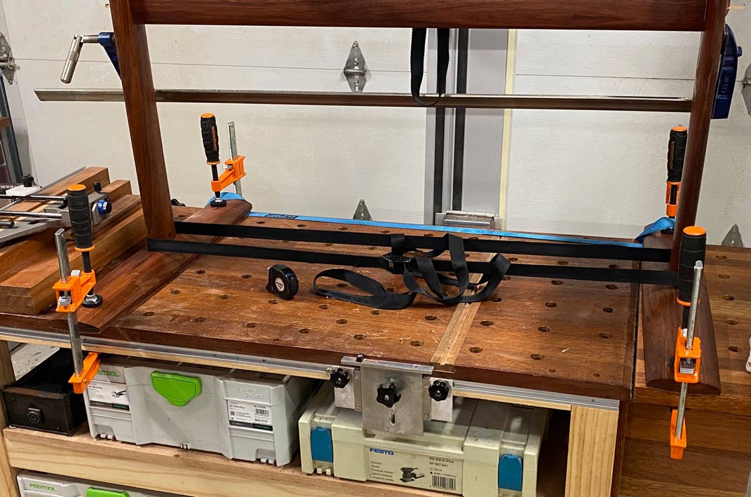
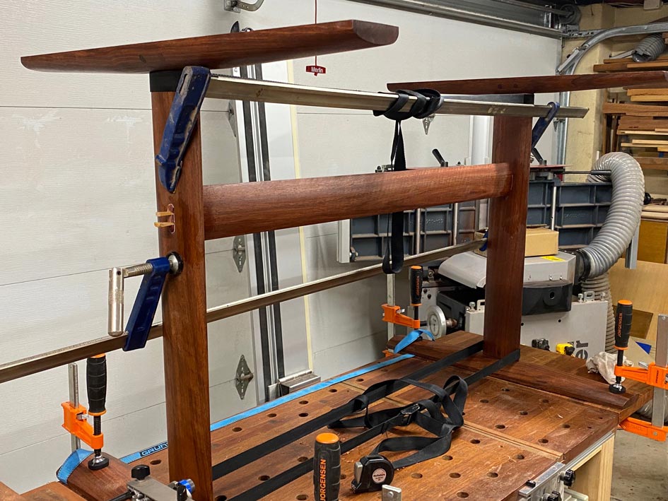
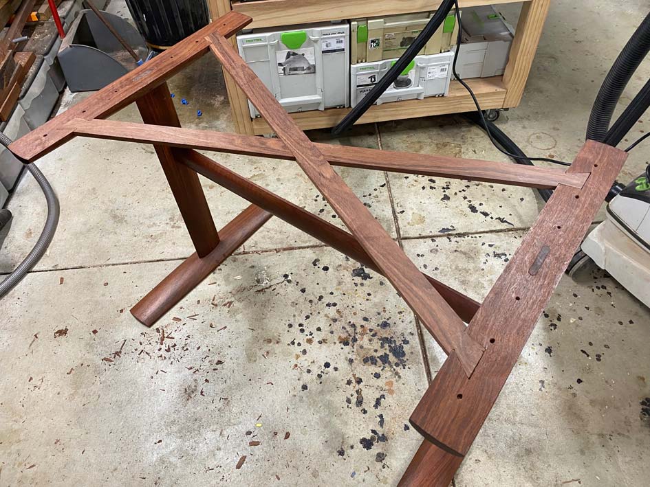
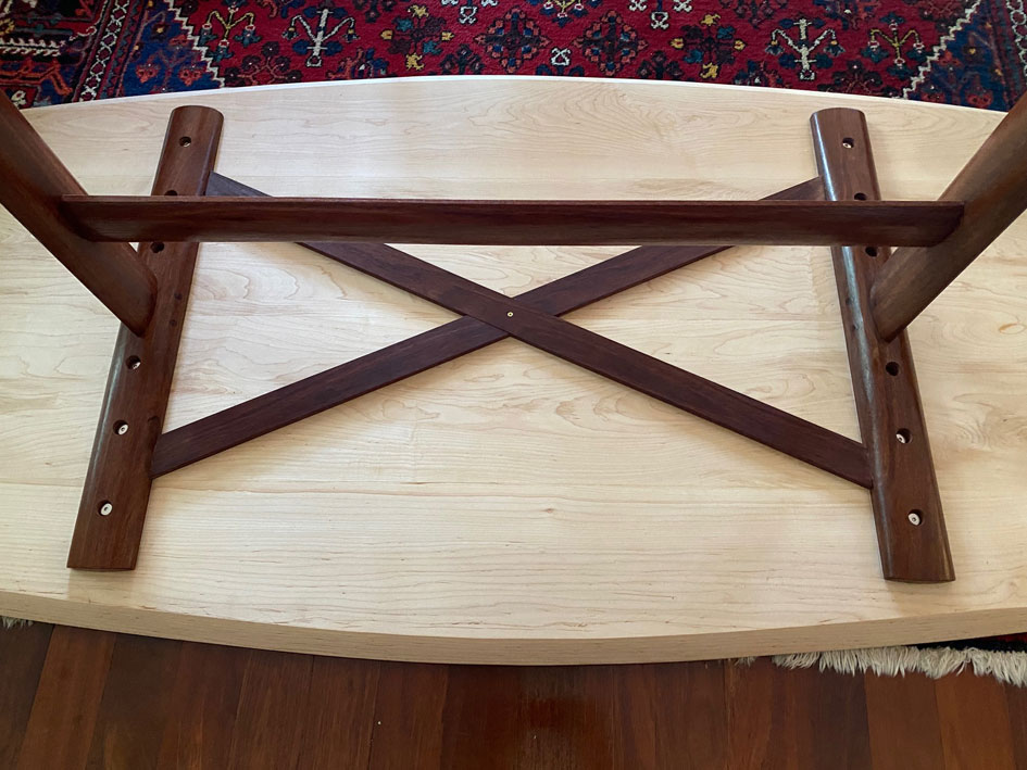
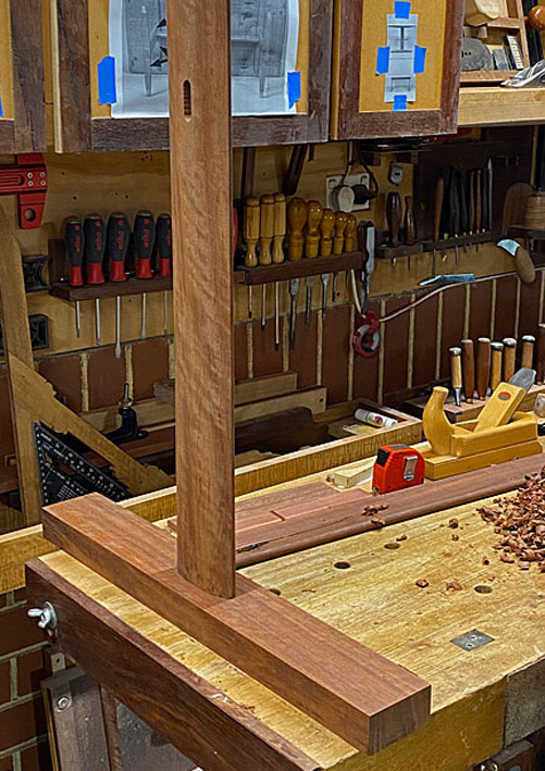
All the base parts cut to length and width, and mortised ...
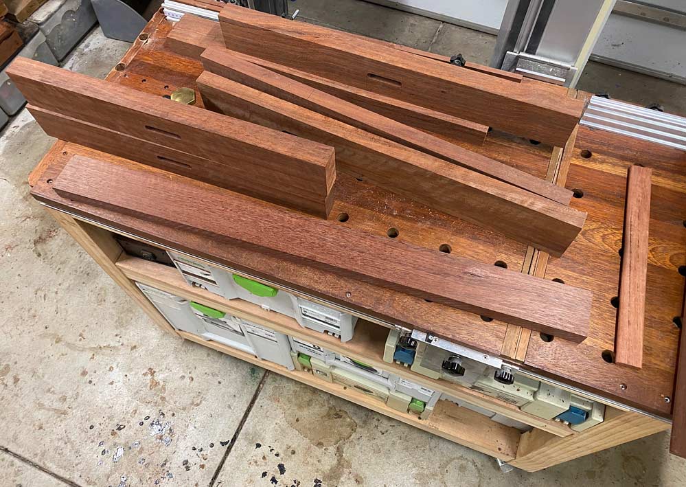
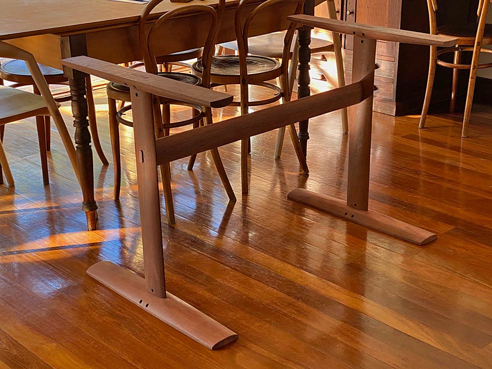
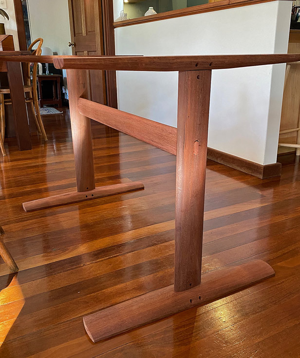
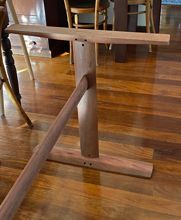
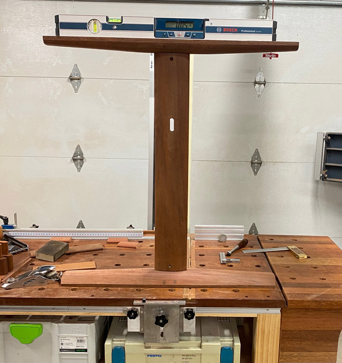
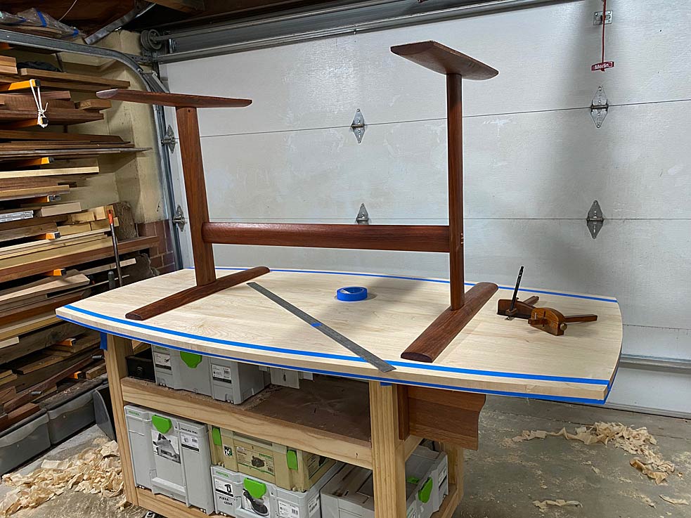
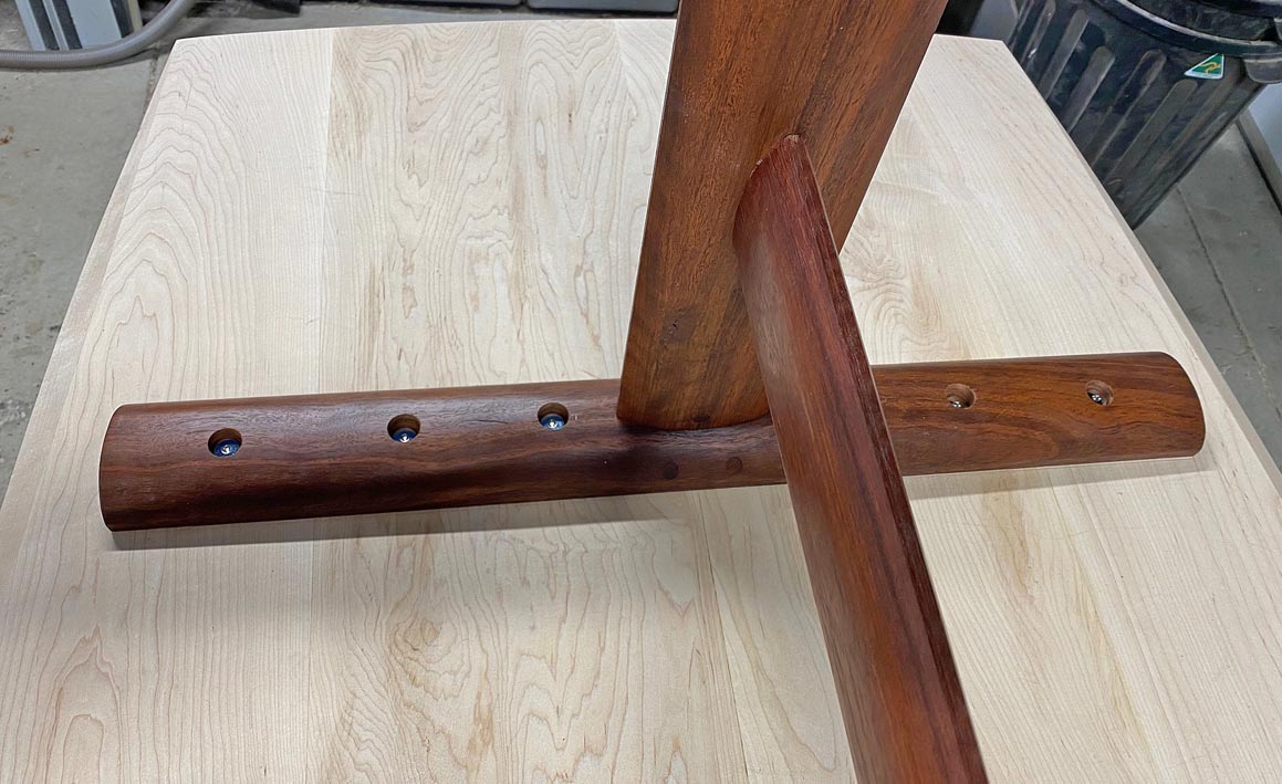
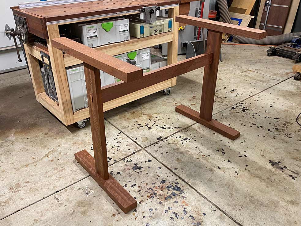
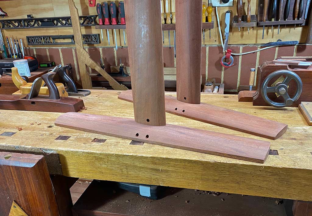
A loose fit. There is just over 1m (40") between the trestle ends, with a 16" overhang planned. 72" long in total. Note that the top support is wider than the base. Both will be carved away for an "organic" blend with the upright sections. It looks a little stick-like at present ...
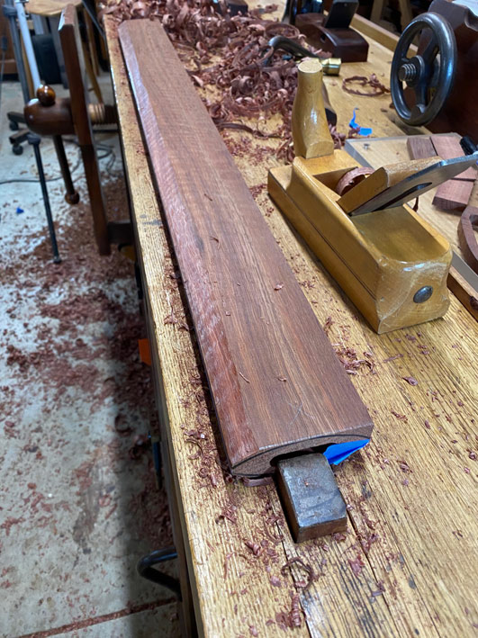
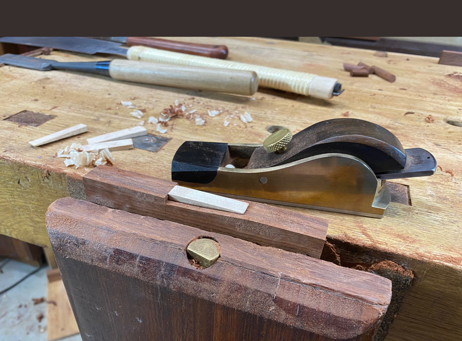
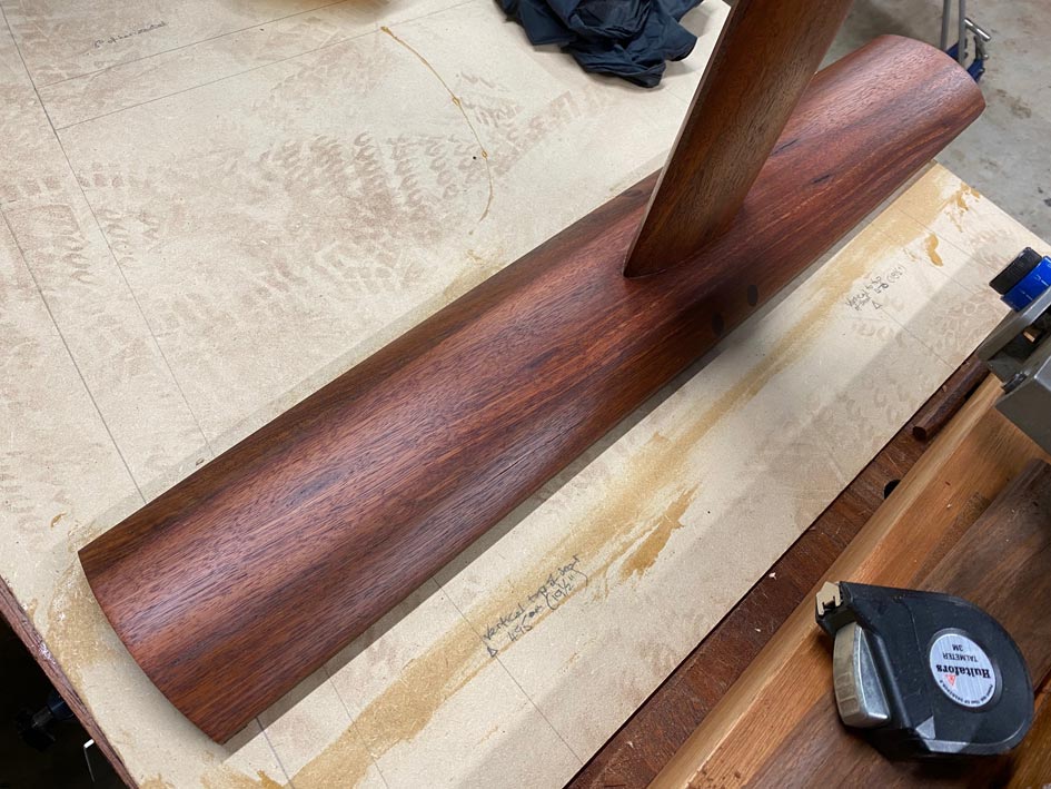
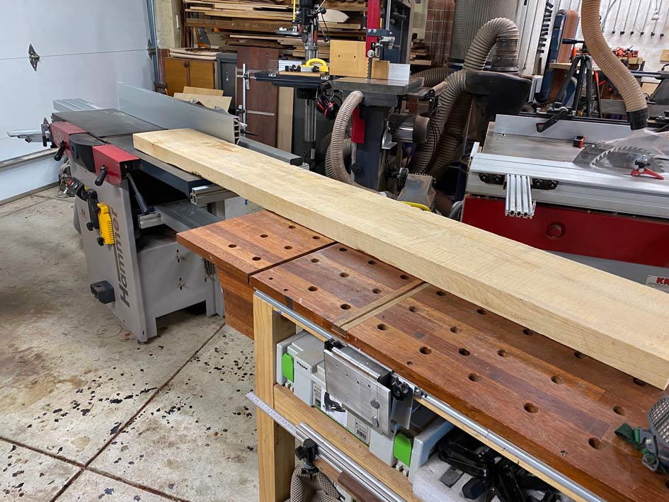
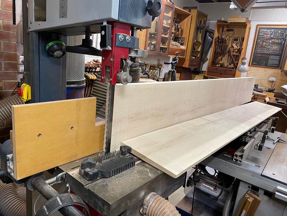
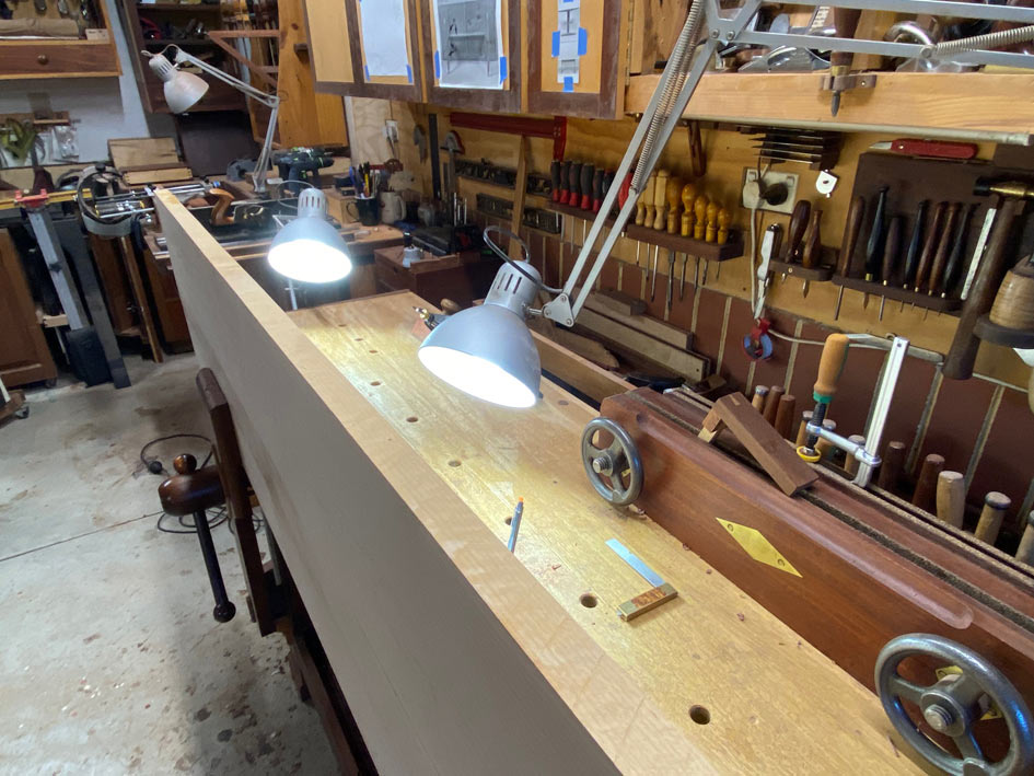
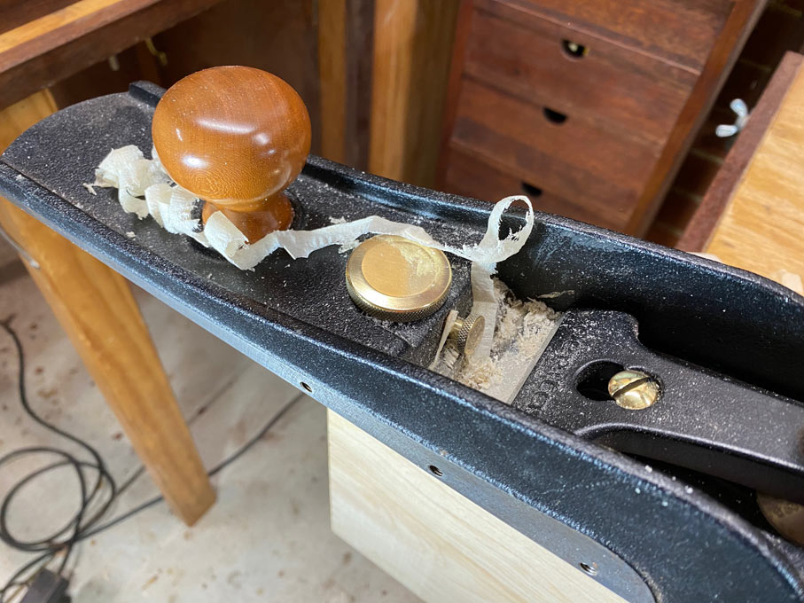
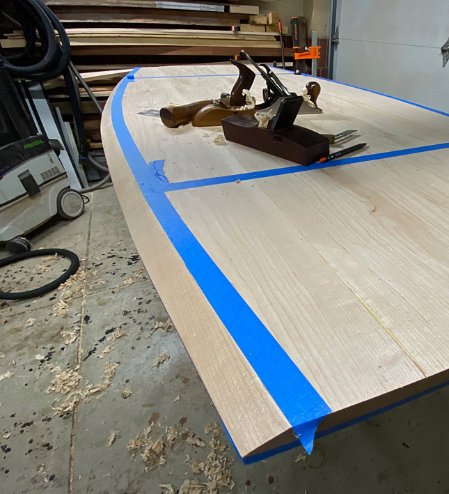
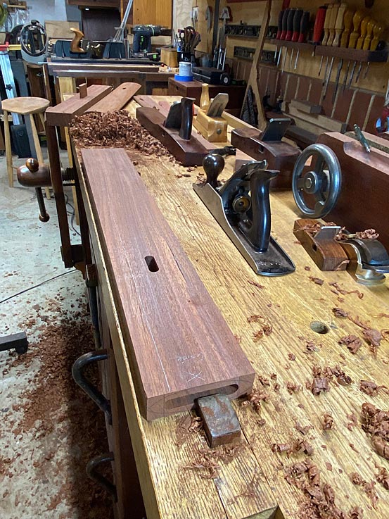
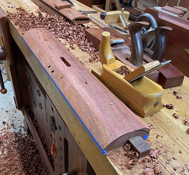
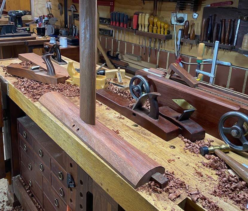
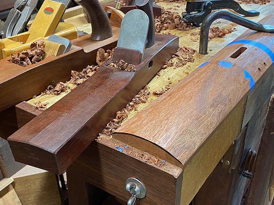
Here is one leg or, rather, one upright. Everyone likes looking at shavings and planes. Start with a jack ... in this case a Stanley #605 with a radiused blade ... follow with a HNT Gordon Trying Plane to remove any tearout, and more shaping with smaller planes ...
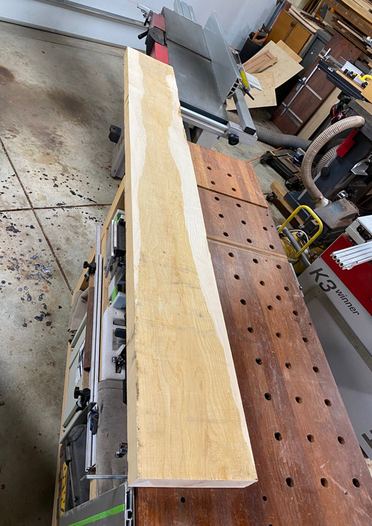
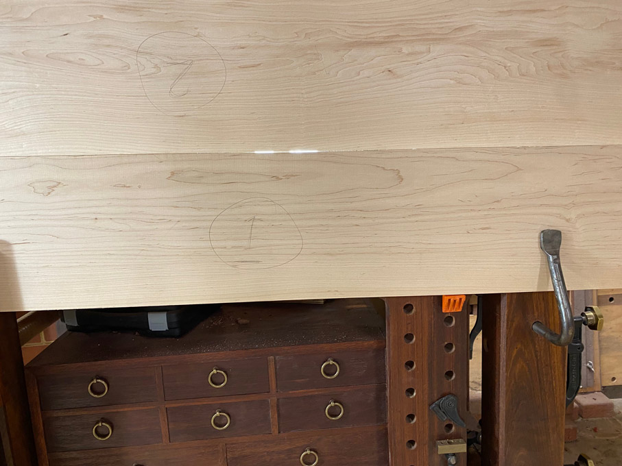
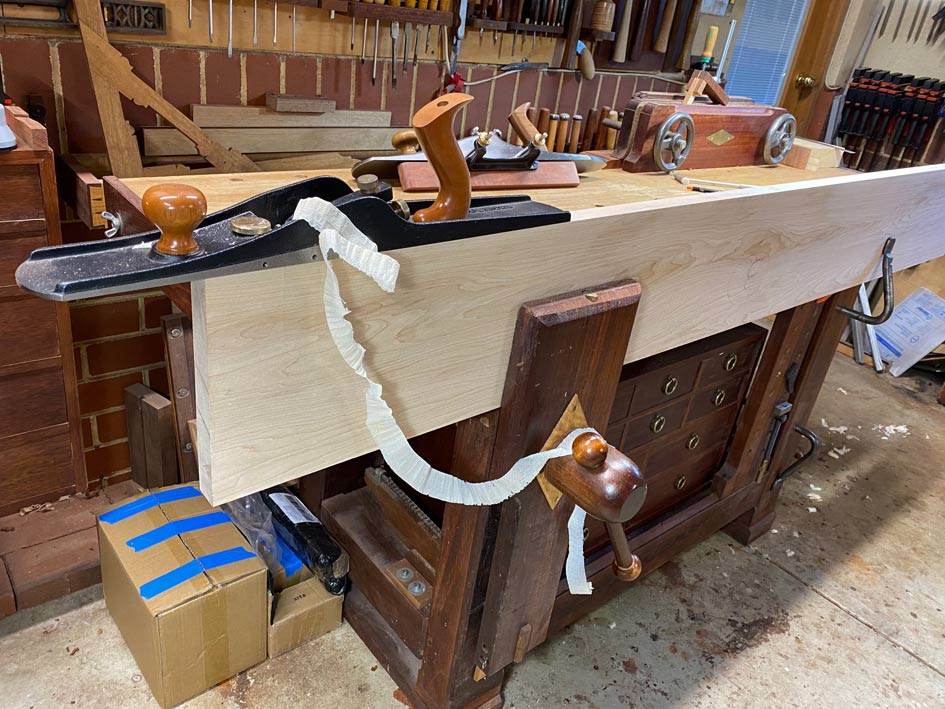
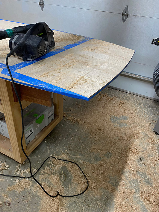
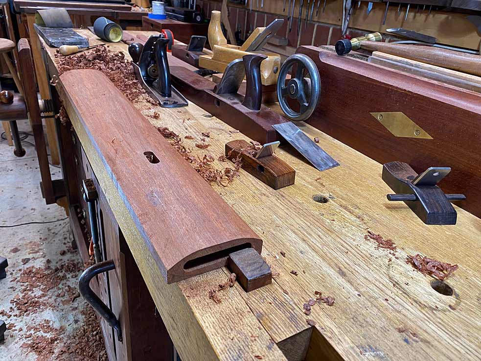
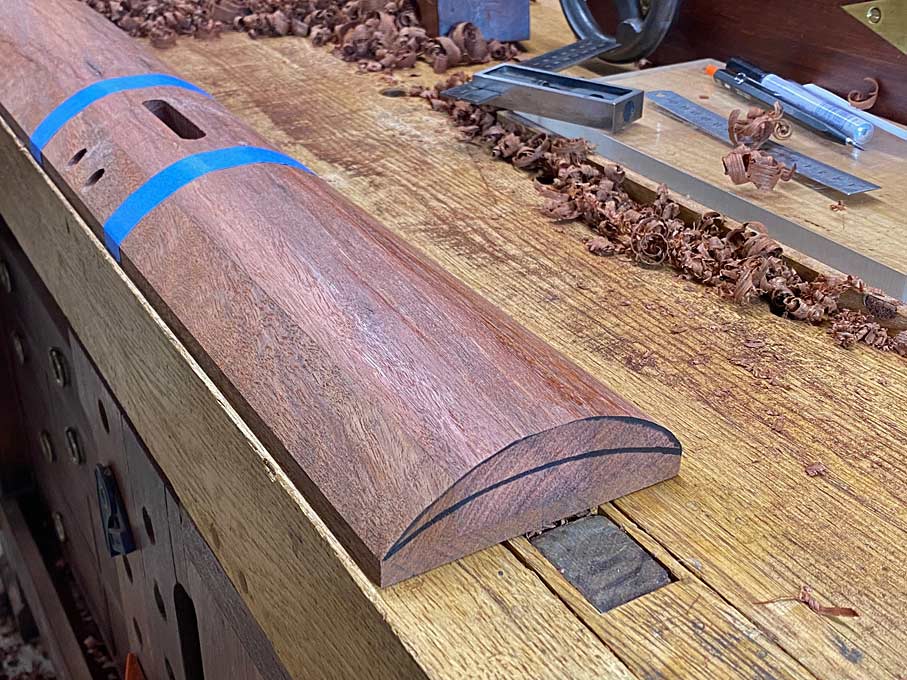
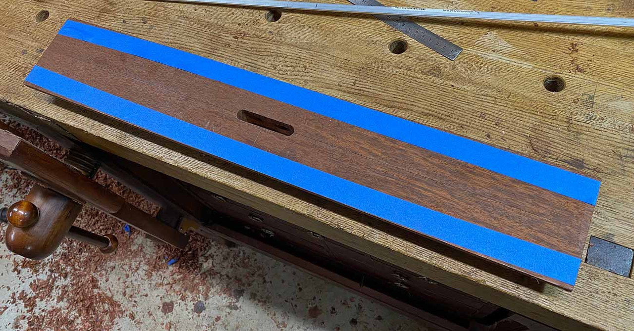
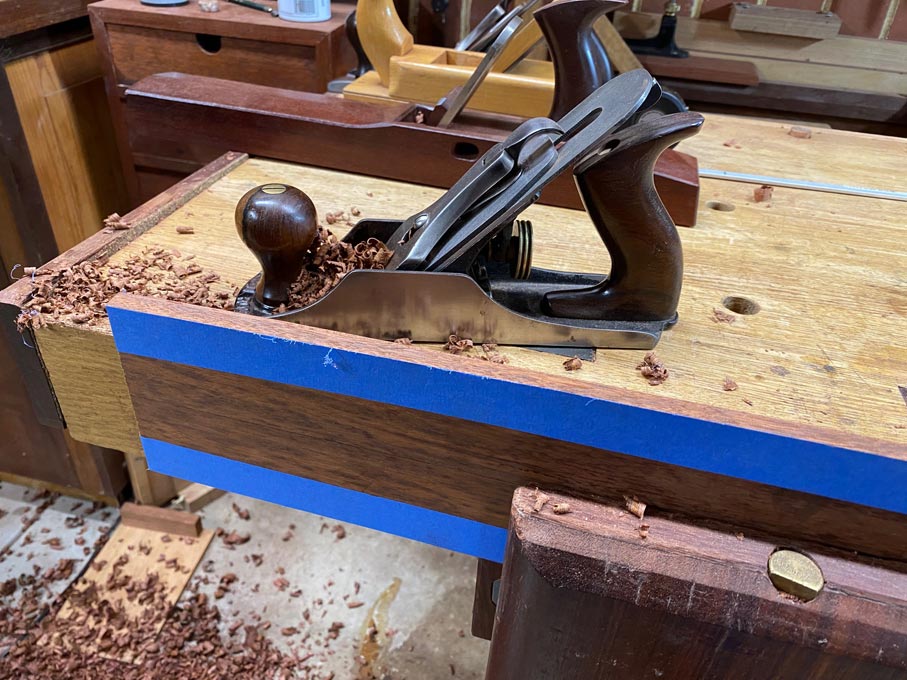
Planing down to the marked curved lines ...
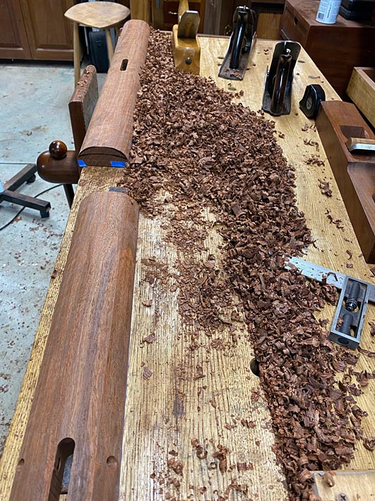
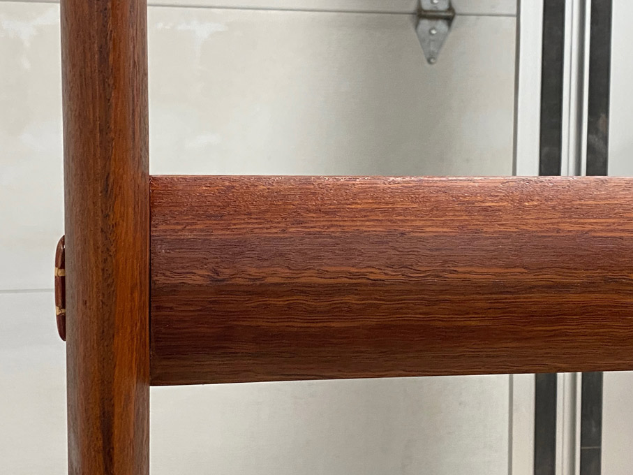
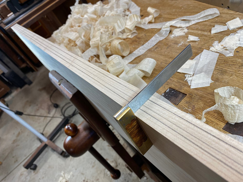
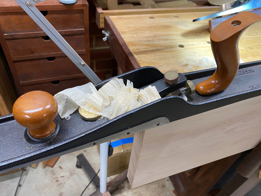
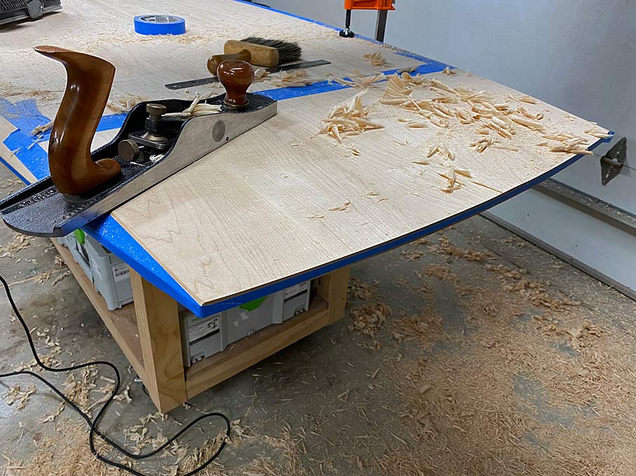
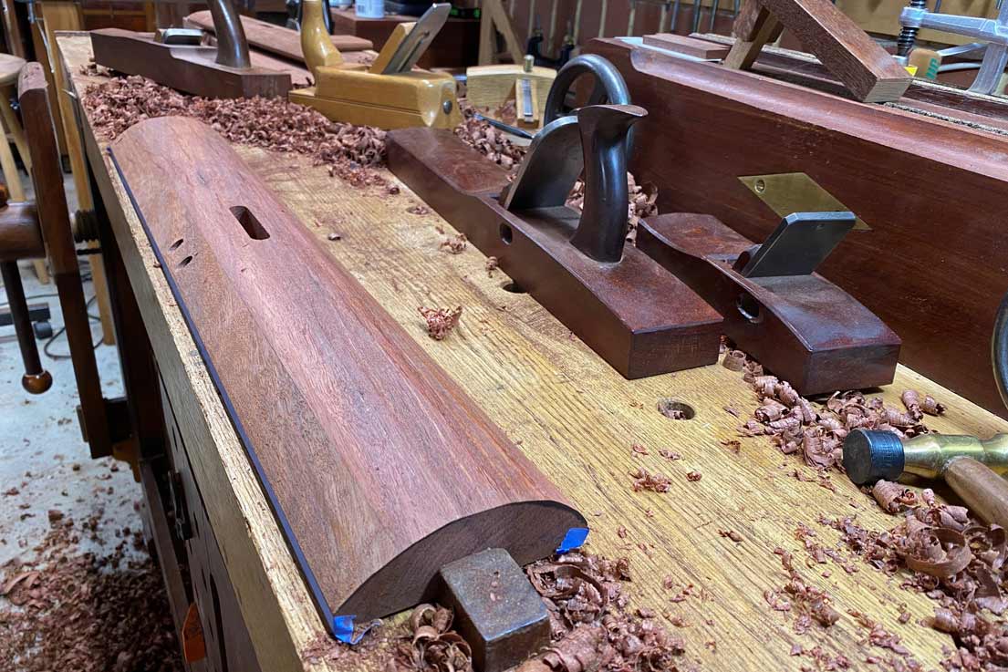
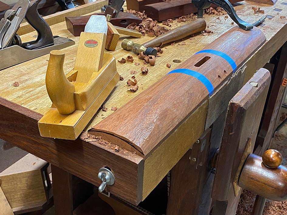
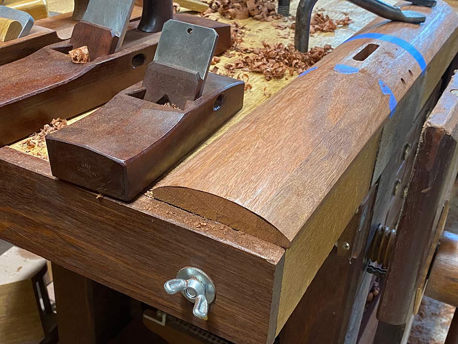
The tiny high angle BU smoother I made worked its magic ...
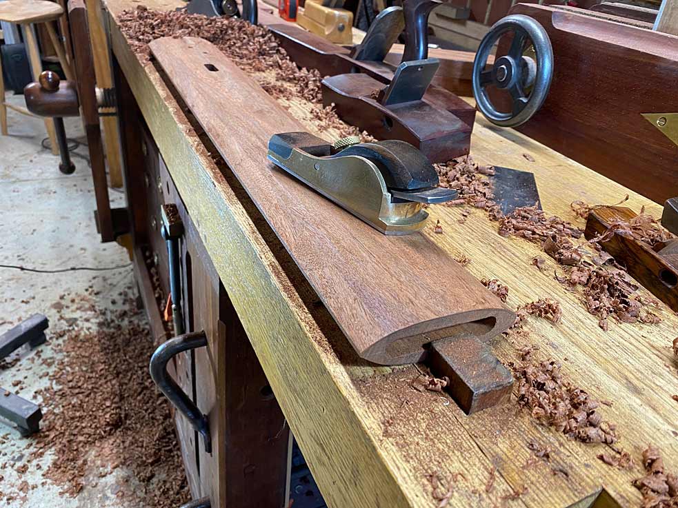
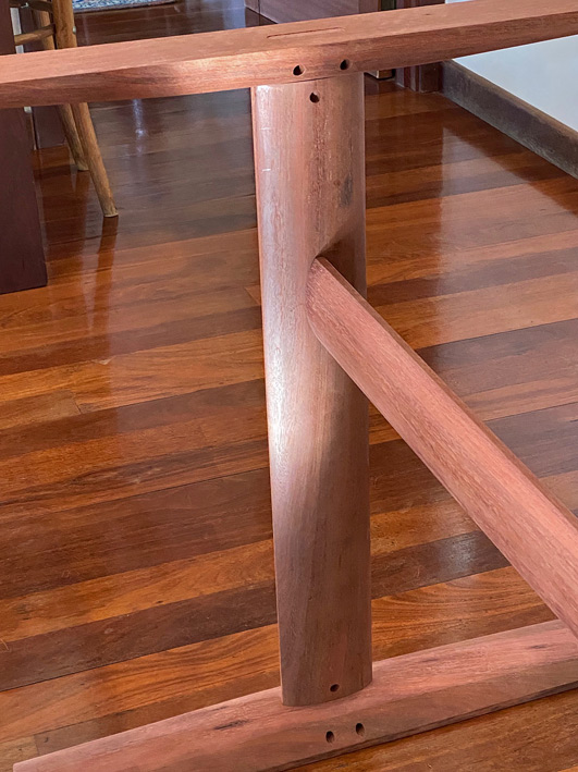
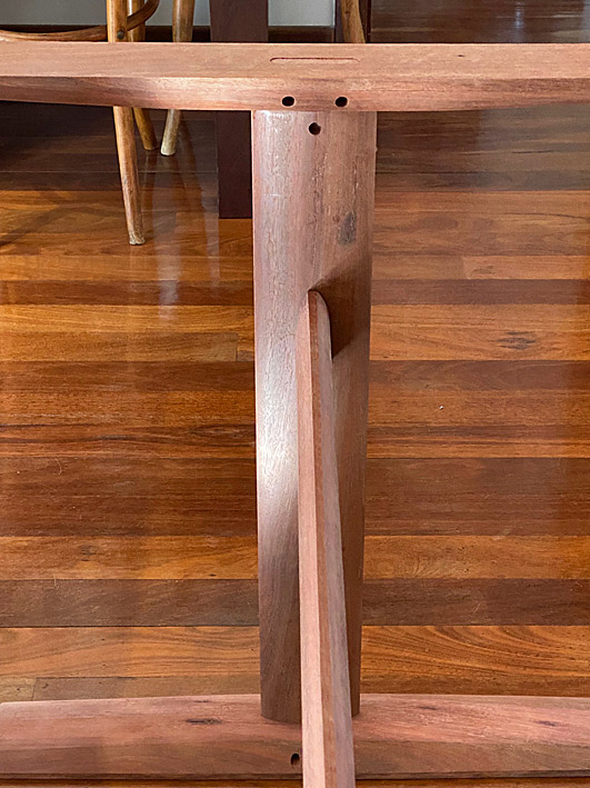
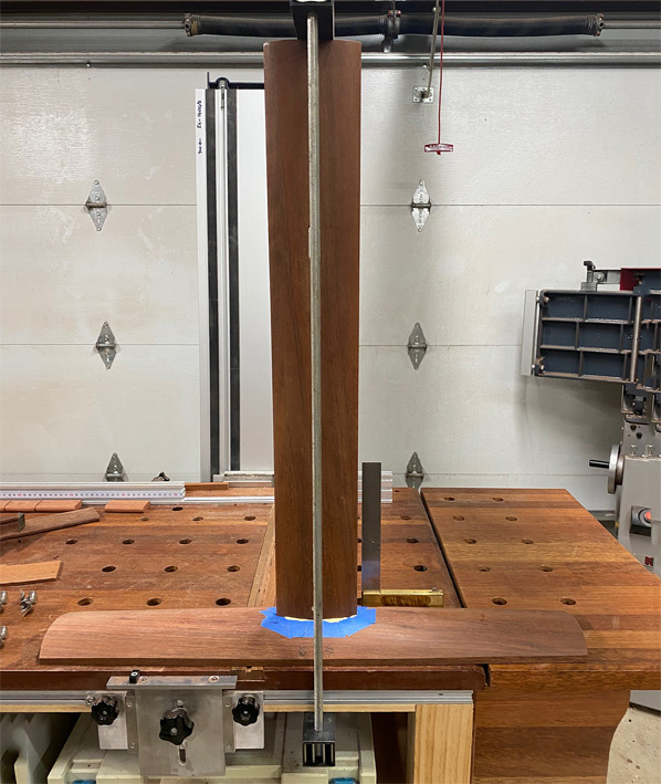
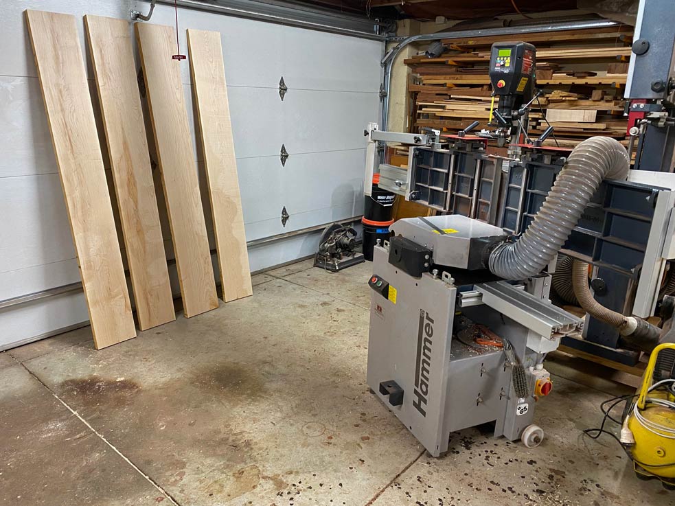
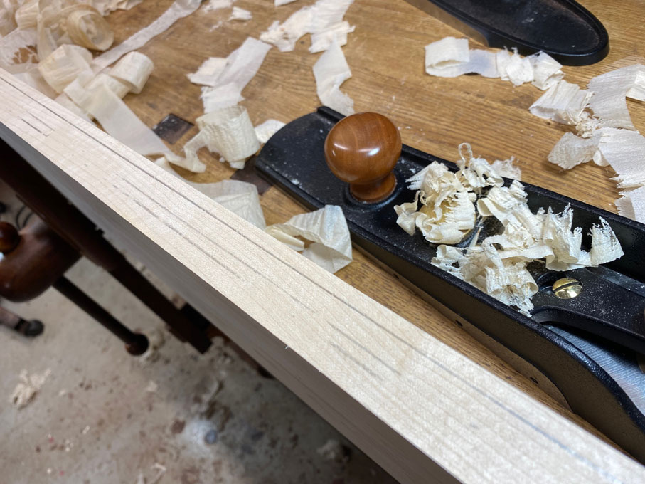
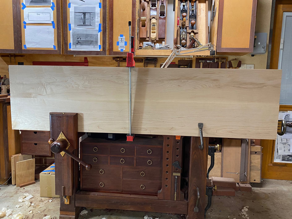
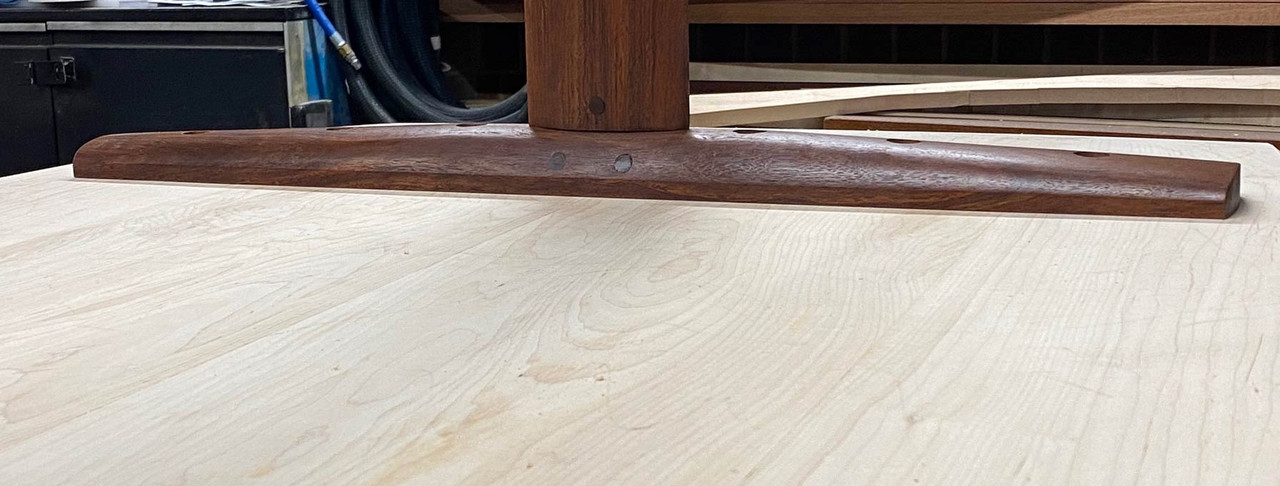
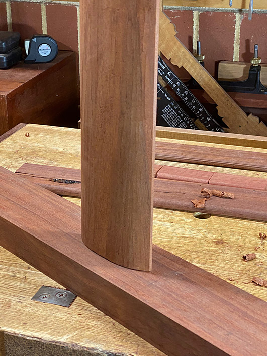
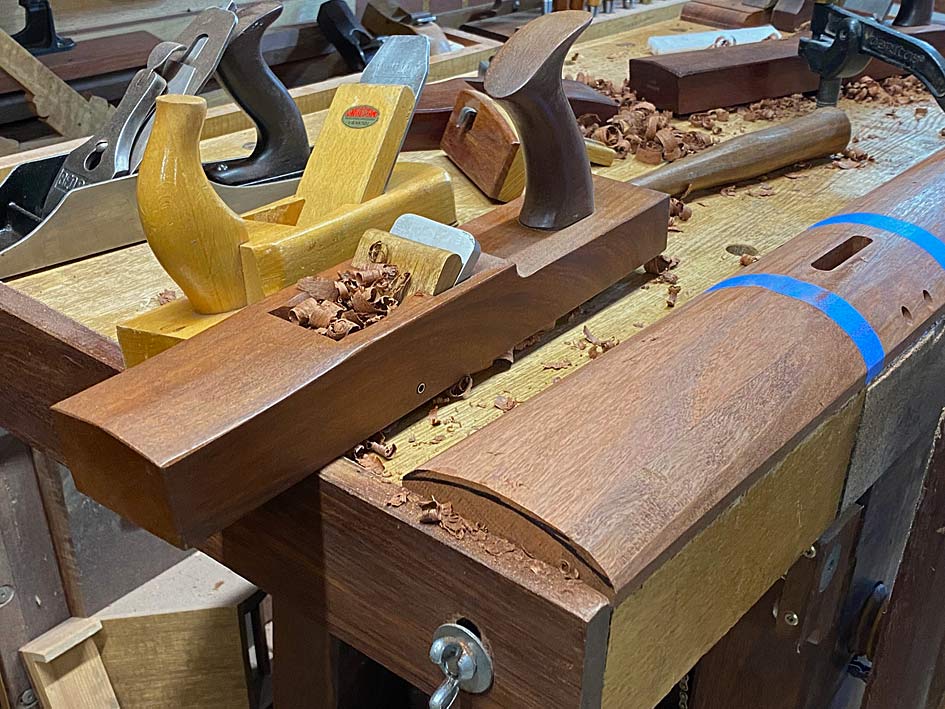
Posts shaped into an ellipse ..
I have made up some basic drawings and plans, but nothing I want to show here. Instead, I am posting photos of tables I found which have similarities - this is just to offer up some concepts to aid in visualising what I am planning. My design is different in important areas, but there are indeed similarities ...Here is a table made by Borge-Morgensen, which has similar dimensions for the parts. The construction is very similar.
I have made up some basic drawings and plans, but nothing I want to show here. Instead, I am posting photos of tables I found which have similarities - this is just to offer up some concepts to aid in visualising what I am planning. My design is different in important areas, but there are indeed similarities ...Here is a table made by Borge-Morgensen, which has similar dimensions for the parts. The construction is very similar.
The top will be made from Rock Maple, and 1825mm long (72") x 900mm (35") wide, and 30mm thick. At present my first choice is to use a shallow elliptical router bit, creating a pillowed (very slightly rounded) face to soften the edge. This is in keeping with the chairs, which are all curvy. The second choice - if this leaves the top looking too thick - is to use a shallow undercut chamfer. Note that the top will be curved along all sides.Something like this Nakashima table ...
The legs link to the chairs through an oval shape I plan to give them (the legs of the chairs are oval) ... both in the horizontal and vertical parts. Joinery is pinned loose mortise-and-tenon and not the bridle joint in the Nakashima photo.The light Rock Maple top will appear to float on the dark Jarrah base. That is the intention.
A comment about the DC 09 Chairs I built: When we were planning to build a larger table, it was necessary to add two more chairs. My initial thought was to find bentwood carvers to join the existing bent wood chairs, but we did not like their looks, and went searching for something else. Much of our furniture is contemporary, Mid Century-styled (as you may have noticed from my builds), and so I decided to add two modern carvers (we do not mind a mix-and-match), and use the table to blend all the pieces together.
I managed to do a little work on the trestle table this weekend, in between watching the Olympic Games.
The mortise and tenon joinery is all loose tenons, which is easier to do accurately since all are through mortises. Plus I can orient the grain in the tenons for maximum strength (i.e. no run out).
With the exception of the cross support, all mortises are 1/2" x 70mm wide x 40mm deep. The cross support mortises are 1/2" x 40mm wide x 40mm deep.
The loose tenon stock is made simply and quickly: thickness quarter sawn Jarrah, saw to width, and round over with a 1/4 round bit in a trim router.
One correction for the loose tenons: the loose tenon is actually 80mm (3 1/8") long. The root is 40mm. And will be pinned at each end. That is pretty substantial. The rail will be wedged.
Regarding the choice of loose tenon joinery in this build: I have a preference for traditional mortise-and-tenon joinery. When I started making the chairs, this is what I did - integrated tenons from the seats. Then it became evident that they were vulnerable to breaking owing to run out. That is not a risk to take with chair legs. I started again, and this time used loose tenons, which allowed me to choose quarter-sawn stock.
The wedged M&T legs ...
... need to be echoed in the table. Hence the round ends (made with a router) in the table legs. Also the oval table legs linking to the oval chair legs.
Now we get to the interesting part. What I start with will be quite different from what ends up finished. There is very little that will not be carved away. Remember, the table is intended to blend with the two chairs I built. For this reason, the two vertical sections and the horizontal cross support will be oval in cross section. I have not seen this before ...
A template for later use ...
All the base parts cut to length and width, and mortised ...
A loose fit. There is just over 1m (40") between the trestle ends, with a 16" overhang planned. 72" long in total. Note that the top support is wider than the base. Both will be carved away for an "organic" blend with the upright sections. It looks a little stick-like at present ...
Here is one leg or, rather, one upright. Everyone likes looking at shavings and planes. Start with a jack ... in this case a Stanley #605 with a radiused blade ... follow with a HNT Gordon Trying Plane to remove any tearout, and more shaping with smaller planes ...
Planing down to the marked curved lines ...
The tiny high angle BU smoother I made worked its magic ...
Posts shaped into an ellipse ..

")