

- Joined
- Jul 21, 2014
- Messages
- 10,414
- Reaction score
- 165
I showed some early photos of my current thicknesser storage stand here http://www.thewoodhaven2.co.uk/viewtopi ... ser#p19206
It currently stores/supports a DW733 mk1 lunchbox planer. the planer is flipped over and stored upside down and the stand rolls under the bench out of the way when not used.
I estimate the planer might weigh about 30 kgs and I used a pair of gas springs to help counterbalance the weight whilst flipping it.
My new thicknesser is a heavy beast possibly over 200kg and I'm not confident that I can safely counterbalance this sort of weight to use the same method.
After a bit of thinking I've come up with an elevating stand where the planer will drop down from the operating position by around 550mm into the stand and so be able to be rolled under the bench out of the way.
I've made a whole load of measurements of critical dimensions and a number of 2D drawings of key regions but the rest of the stand is still between my ears until today when I took the sketchup challenge to sketch what I plan to make and help to explain it to you.
This is the basic stand housing.
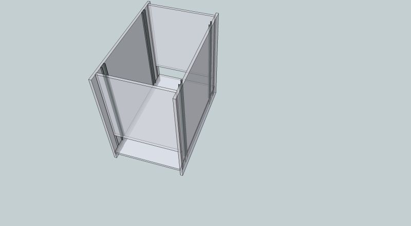
It is a box made from 18mm MRMDF with the joints set into 2mm deep dados.
The 4 dark grey strips are the outer part of full extension drawer slides - the rest of the mechanism is not used but returned to the project box for another day.
These strips are the guides to make sure the platform that carries the thicknesser (not shown) can rise and fall smoothly and not rack side to side or front to back.
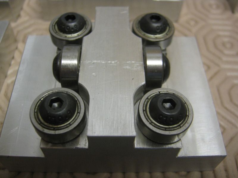
This is the block that will run inside the strips. it is a block of aluminium fitted with 6 miniature ball races
5mm wide, 14mm diameter and 5mm bore.
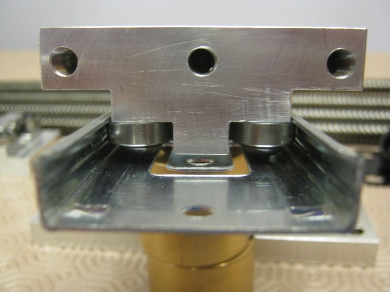
I've tried to show it fitted in the strip in this photo.
Back to sketchup, this shows the 4 jack screws in red that will lift the platform up and down.
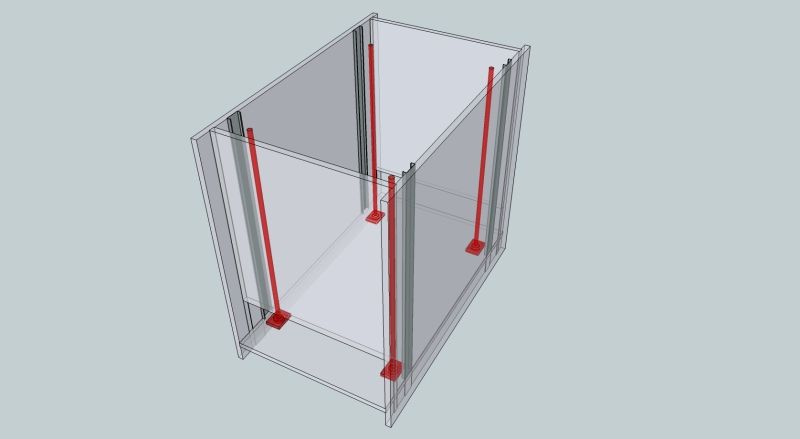
At the bottom of each jack screw is a bearing to take the thrust ( at least 50kg per jack)
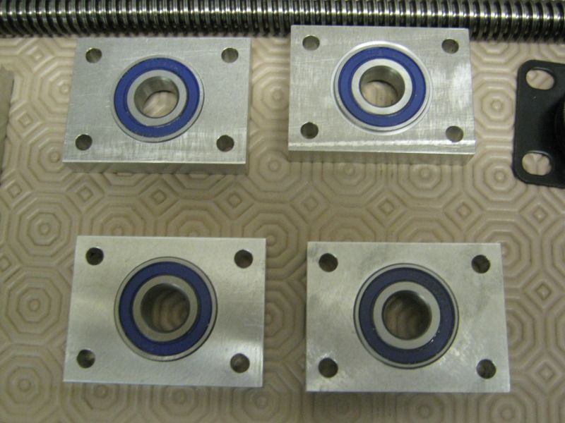
Immediately below these bearing blocks are heavy duty casters transmitting the load direct to the floor.
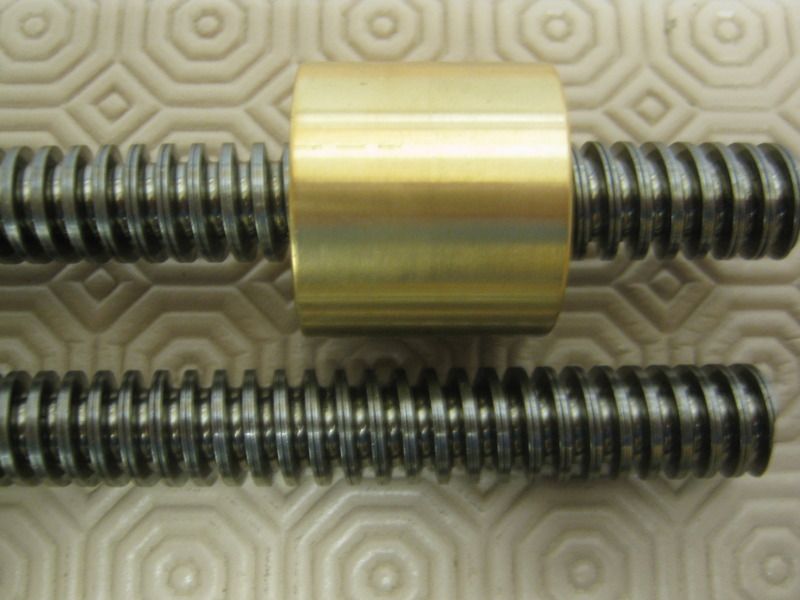
The jackscrews are lengths of threaded rod with an acme thread (4mm pitch - one turn lifts 4mm). This is the type of thread found on quality clamps and designed for heavy loads. Matching bronze nuts offer lower friction in combination with the steel as well as minimal wear and good strength.
The next sketchup figure shows the guide blocks in the strips at the approx upper end of the travel.
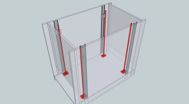
This is a s far as I've got with sketchup. What is not shown is a sprocket at the base of each jack screw and the roller chain that will connect them. Also not shown are the bronze nuts which will be bolted to the lifting platform and the guide blocks
I have a motor from an electric golf caddy that I hope to use to drive the chain but that needs experimentation once the mechanism is working.
The key to the design is that the load is transmitted direct to the floor with metal components and the mdf box does little more than keep the load vertically over the wheels and stop the machine from moving laterally.
Thanks for looking.
Bob
It currently stores/supports a DW733 mk1 lunchbox planer. the planer is flipped over and stored upside down and the stand rolls under the bench out of the way when not used.
I estimate the planer might weigh about 30 kgs and I used a pair of gas springs to help counterbalance the weight whilst flipping it.
My new thicknesser is a heavy beast possibly over 200kg and I'm not confident that I can safely counterbalance this sort of weight to use the same method.
After a bit of thinking I've come up with an elevating stand where the planer will drop down from the operating position by around 550mm into the stand and so be able to be rolled under the bench out of the way.
I've made a whole load of measurements of critical dimensions and a number of 2D drawings of key regions but the rest of the stand is still between my ears until today when I took the sketchup challenge to sketch what I plan to make and help to explain it to you.
This is the basic stand housing.

It is a box made from 18mm MRMDF with the joints set into 2mm deep dados.
The 4 dark grey strips are the outer part of full extension drawer slides - the rest of the mechanism is not used but returned to the project box for another day.
These strips are the guides to make sure the platform that carries the thicknesser (not shown) can rise and fall smoothly and not rack side to side or front to back.

This is the block that will run inside the strips. it is a block of aluminium fitted with 6 miniature ball races
5mm wide, 14mm diameter and 5mm bore.
I've tried to show it fitted in the strip in this photo.

Back to sketchup, this shows the 4 jack screws in red that will lift the platform up and down.

At the bottom of each jack screw is a bearing to take the thrust ( at least 50kg per jack)

Immediately below these bearing blocks are heavy duty casters transmitting the load direct to the floor.
The jackscrews are lengths of threaded rod with an acme thread (4mm pitch - one turn lifts 4mm). This is the type of thread found on quality clamps and designed for heavy loads. Matching bronze nuts offer lower friction in combination with the steel as well as minimal wear and good strength.

The next sketchup figure shows the guide blocks in the strips at the approx upper end of the travel.

This is a s far as I've got with sketchup. What is not shown is a sprocket at the base of each jack screw and the roller chain that will connect them. Also not shown are the bronze nuts which will be bolted to the lifting platform and the guide blocks
I have a motor from an electric golf caddy that I hope to use to drive the chain but that needs experimentation once the mechanism is working.
The key to the design is that the load is transmitted direct to the floor with metal components and the mdf box does little more than keep the load vertically over the wheels and stop the machine from moving laterally.
Thanks for looking.
Bob

 How did I miss that......


 .
.


 bscene-drinkingbuddies:


