• Hi all and welcome to TheWoodHaven2 brought into the 21st Century, kicking and screaming! We all have Alasdair to thank for the vast bulk of the heavy lifting to get us here, no more so than me because he's taken away a huge burden of responsibility from my shoulders and brought us to this new shiny home, with all your previous content (hopefully) still intact! Please peruse and feed back. There is still plenty to do, like changing the colour scheme, adding the banner graphic, tweaking the odd setting here and there so I have added a new thread in the 'Technical Issues, Bugs and Feature Requests' forum for you to add any issues you find, any missing settings or just anything you'd like to see added/removed from the feature set that Xenforo offers. We will get to everything over the coming weeks so please be patient, but add anything at all to the thread I mention above and we promise to get to them over the next few days/weeks/months. In the meantime, please enjoy!

Elevating stand for my new thicknesser

9fingers

Moderator
Staff member
Joined
Jul 21, 2014
Messages
10,414
Reaction score
165
Location
Romsey Hampshire between Southampton and the New F
I showed some early photos of my current thicknesser storage stand here http://www.thewoodhaven2.co.uk/viewtopi ... ser#p19206

It currently stores/supports a DW733 mk1 lunchbox planer. the planer is flipped over and stored upside down and the stand rolls under the bench out of the way when not used.
I estimate the planer might weigh about 30 kgs and I used a pair of gas springs to help counterbalance the weight whilst flipping it.

My new thicknesser is a heavy beast possibly over 200kg and I'm not confident that I can safely counterbalance this sort of weight to use the same method.
After a bit of thinking I've come up with an elevating stand where the planer will drop down from the operating position by around 550mm into the stand and so be able to be rolled under the bench out of the way.

I've made a whole load of measurements of critical dimensions and a number of 2D drawings of key regions but the rest of the stand is still between my ears until today when I took the sketchup challenge to sketch what I plan to make and help to explain it to you.


This is the basic stand housing.
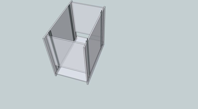

It is a box made from 18mm MRMDF with the joints set into 2mm deep dados.
The 4 dark grey strips are the outer part of full extension drawer slides - the rest of the mechanism is not used but returned to the project box for another day.

These strips are the guides to make sure the platform that carries the thicknesser (not shown) can rise and fall smoothly and not rack side to side or front to back.
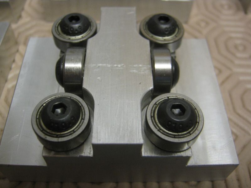


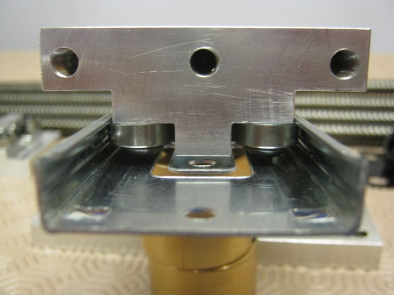
This is the block that will run inside the strips. it is a block of aluminium fitted with 6 miniature ball races
5mm wide, 14mm diameter and 5mm bore.

I've tried to show it fitted in the strip in this photo.


Back to sketchup, this shows the 4 jack screws in red that will lift the platform up and down.
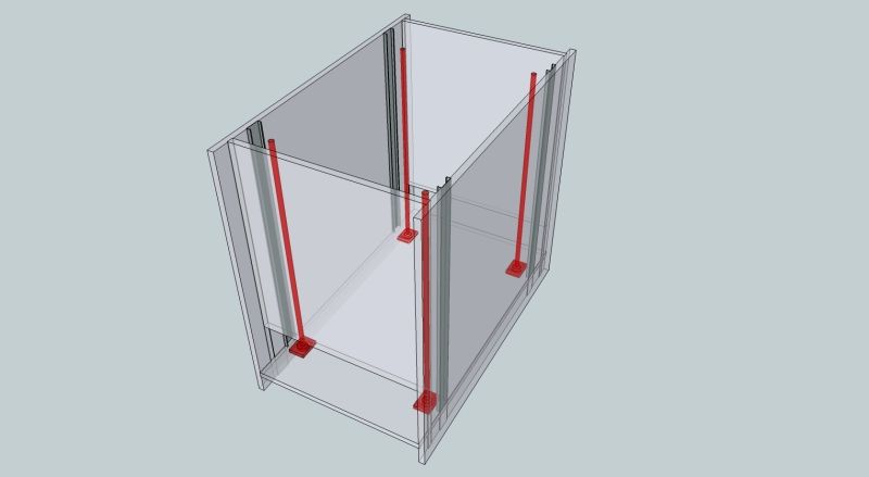


At the bottom of each jack screw is a bearing to take the thrust ( at least 50kg per jack)
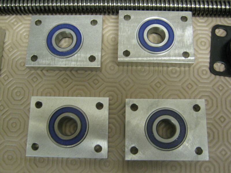


Immediately below these bearing blocks are heavy duty casters transmitting the load direct to the floor.

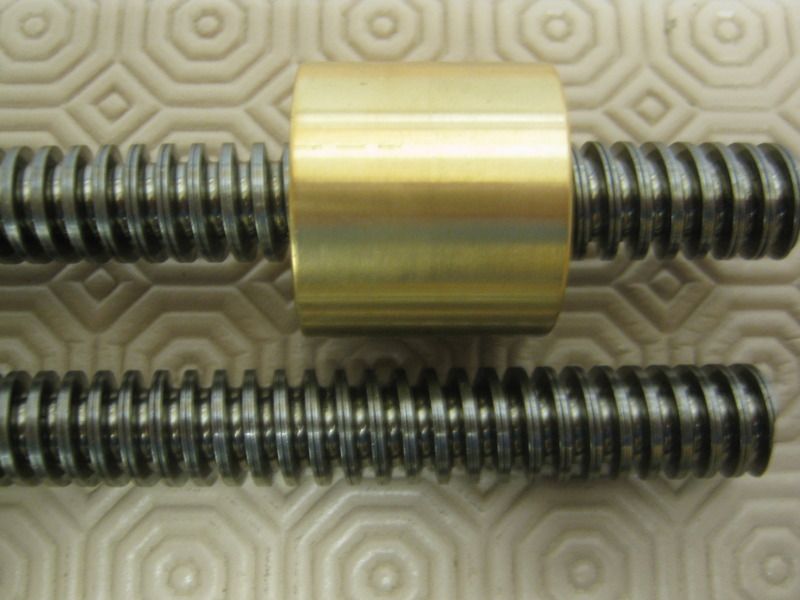
The jackscrews are lengths of threaded rod with an acme thread (4mm pitch - one turn lifts 4mm). This is the type of thread found on quality clamps and designed for heavy loads. Matching bronze nuts offer lower friction in combination with the steel as well as minimal wear and good strength.


The next sketchup figure shows the guide blocks in the strips at the approx upper end of the travel.
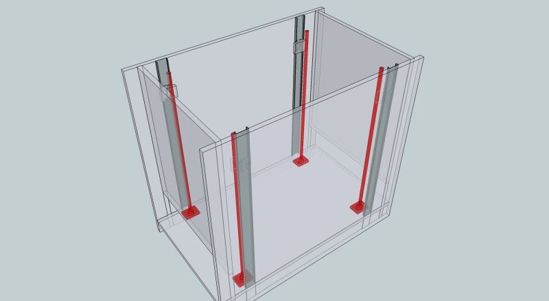


This is a s far as I've got with sketchup. What is not shown is a sprocket at the base of each jack screw and the roller chain that will connect them. Also not shown are the bronze nuts which will be bolted to the lifting platform and the guide blocks
I have a motor from an electric golf caddy that I hope to use to drive the chain but that needs experimentation once the mechanism is working.

The key to the design is that the load is transmitted direct to the floor with metal components and the mdf box does little more than keep the load vertically over the wheels and stop the machine from moving laterally.

Thanks for looking.

Bob
 
Are you going to have some sort of bicycle chain arrangement for turning all the threaded rods at the same speed and time?
 
I just knew that would happen! :D How did I miss that......
 
Mike G":1evqunhp said:
I just knew that would happen! :D How did I miss that......

No worries Mike. You had me going for a bit as I thought I had left that part out. This design has been buzzing round in my head for a while now and it is easy to think that something has been said or done when instead I've just thought about it. Worst time is when I wake in the night with a minor "eureka moment" over some issue or other and forget to add it to the drawings in the morning.

I guess you may have similar things happening with the house build or indeed the propeller project.

Bob
 
It happened most often with an invention I patented in SA a couple or 3 years ago. Minor parts needed a disproportionate amount of thought and design input.
 
I think that will work OK. It's a bigger version of how the thicknesser bed rises and falls in my Axminster Perform planner thicknesser.
 
DaveL":2igce36c said:
I think that will work OK. It's a bigger version of how the thicknesser bed rises and falls in my Axminster Perform planner thicknesser.

The Elektra Bekhum works the same.

Bob, some very nice machining and a very good idea.

Cheers
Phil
 
Looking very good so far Bob, will be watching with interest. Though I am a bit worried that this is distracting you from those bookcases ;) .

Terry.
 
Wizard9999":2adckvrj said:
Looking very good so far Bob, will be watching with interest. Though I am a bit worried that this is distracting you from those bookcases ;) .

Terry.

ISTR that you were interested in the lift method so glad you have spotted the thread. You should not concern yourself over bookcase progress as machining the parts for the lift is a useful fill in job whilst waiting for finish stages on the bookcases batch to dry. The wood workshop needs to be kept as free as possible from air borne dust during these latter phases so retiring to the metal workshop is ideal.

Bob
 
9fingers":o3441kkp said:
Wizard9999":o3441kkp said:
Looking very good so far Bob, will be watching with interest. Though I am a bit worried that this is distracting you from those bookcases ;) .

Terry.

ISTR that you were interested in the lift method so glad you have spotted the thread. You should not concern yourself over bookcase progress as machining the parts for the lift is a useful fill in job whilst waiting for finish stages on the bookcases batch to dry. The wood workshop needs to be kept as free as possible from air borne dust during these latter phases so retiring to the metal workshop is ideal.

Bob

Looks like you are burning the midnight oil Bob! Should have guessed there was perfect synergy, I remember you advocating lists of different types of jobs so they can be fitted together.

Forgive my stupidity, but what does "ISTR" mean?

Terry.

Edit: does it mean "I Seem To Recall", just had a rare moment of inspiration :lol: .
 
Commander":2inixe8f said:
Looks brilliant so far Bob! I'm excited to see this one come together!


Thanks Erich. I hope to get some more workshop time over the weekend and maybe some more parts ready to photograph.

The acid test is a while down the road yet to see if the motor and gearbox I have from the golf cart is man enough to lift the machine. The fall back option is to go "dumpster diving" at a nearby place that refurbishes wheel chairs for more powerful motor/gearbox combinations.

Bob
 
A few things got in the way over the weekend so it was not until this afternoon I got into the metal workshop.

I had already made some fittings for the lower end of the jackscrews. These have a spigot on the end to sit into the thrust bearing and a bore about 25mm deep to receive the end of the threaded screws.

Two M6 bolts secure the end of the screw into the end fitting and the sprocket to that.


As mentioned earlier the thrust bearing carrier transfers the load to the caster.

The photo show this as fitted to the jack screw/sprocket assembly.


The next photo is a mock-up of two of the four jackscrews in a piece of aluminium channel (to stiffen the structure against the chain tension).


In the centre of the channel is a block with a pair of idler sprockets. These are mounted on hardened steel shoulder bolts and have needle roller bearings in the sprockets.


The next photo show a short piece of chain on the sprockets. A longer version of the loop of chain will have another sprocket on the driving motor.


Hopefully this diagram of the chain path might help clarify the set up


Thanks for looking

Bob
 
9fingers":111x1nb7 said:
DaveL":111x1nb7 said:
Looking good, waiting to the test results.


Me too Dave! According to SWMBO, currently I have to make significant progress on the bookcase varnishing before I can dare make any fresh dust in the wood workshop.
Might be a couple of weeks?
Bob

I can see where your other half is coming from Bob, keen to see those bookcases finished...

...but this is also looking jolly interesting.

So if you wouldn't mind cracking on and getting both moved along :lol: .

Terry.
 
Wizard9999":3ogyoax4 said:
9fingers":3ogyoax4 said:
DaveL":3ogyoax4 said:
Looking good, waiting to the test results.


Me too Dave! According to SWMBO, currently I have to make significant progress on the bookcase varnishing before I can dare make any fresh dust in the wood workshop.
Might be a couple of weeks?
Bob

I can see where your other half is coming from Bob, keen to see those bookcases finished...

...but this is also looking jolly interesting.

So if you wouldn't mind cracking on and getting both moved along :lol: .

Terry.

I share your need for joint project progress. I would help if SWMBO had not organised a lunch out with her friends today and if people stopped ordering inverters from me etc but I'll be doing my best!
Still one bit of good news is that my mates CNC is back up and running with new parts so hopefully no more call outs there for a little while.

I'll just finish this cup of coffee and I'll be back in the workshop wielding sandpaper and varnish brush in 10 minutes.

Bob
 
Well I suppose there could be an opening for someone to do the sanding, varnishing and making the coffee but I happen to know the boss can be a miserable intolerant b'stard at times. :lol:

I suppose I ought to be training someone up on electric motors and modifying inverters to run them .....
Hopefully I have a good few years left in me though!

Bob
 
Next Instalment.

I've now got the varnishing task out of the way and can start risking making some dust now. So last week it was off to get a sheet of MRMDF and cut the panels for the planer stand.
If you recall, the plan is to take all the weight through the metal components but the MDF casing is vital to stop the whole thing racking.

Firstly the base completer with reinforcing aluminium channel fitted.


Within the two pieces of channel, on each "corner" are the thrust bearings for the jack screws.


Flipping the base over you can see the casters.


The outer ones are directly under the jack screws but as the specification of the casters is a little marginal at 50kg each, I've added another four to give me a decent load margin.

This is one of the side panels with dados cut 2mm deep for both the other frame section to sit in and wider slots for the guides.


And with the guides in place.


The next photo shows the platform on which the planer will sit.


Another view with the guides fitted.


A close up on one corner shows the bearing blocks to run in the guides and under the four socket cap screws, just visible, is the bronze nut that will run on the jack screws.


Going back to the base, this photo shows the four jack screws in place


and in close up


Combining the jack screws and the planer platform, the lift is starting to take shape.


and with a side panel in place too.


This trial assembly has not thrown up up any issues - phew! and I now start to think about how to mount the motor and gearbox and a method for adjusting the chain tension. Then some more metal bashing for those parts. Once I am completely satisfied with the wood work, I will seal it with varnish rather than having the inevitable oil staining the mrmdf.

This is the motor and gearbox salvaged from a powered golf caddy that I hope will be man enough for the job.


I hope to be back in a few days with some more progress.

Bob
 
Rod":1yhes17h said:
Looking good - how long will it take to raise (and lower) the platform?

Rod

Rod, I've been fairly conservative on the design in the hope that the motor will cope. Currently it will take just over a minute. I have got the option to increase the supply voltage a bit and if there seems to be torque to spare, I can change the motor sprocket for a bigger one which will speed it up a bit.

Normally if I'm preparing timber, I'll be thicknessing for a few hours so a minute or two at each end of the job will be pretty insignificant.

Bob
 
A few sums.

Assume planer & platform is 250kg. raised through 0.6m in 60 seconds

Work done = 250 x 10 x0.6 joules
Time taken = 60 seconds

Rate of work= Power = 250 x10 x0.6/60 =25 watts

Motor input power 180 watts.

This would allow it to just work if the efficiency of the system is 25/180 or about 14% and I can't believe it will be that poor.

Bob
 
Wizard9999":1currb0t said:
Very impressive Bob :eusa-clap: .
Surprised you are using casters without brakes, am I missing something?

Terry.


Where is it going to go? the floor is flat and it weighs getting on for 1/4 tonne.
Even more to the point, I could not get to the brakes to work them. In fact half the casters had brakes and their first appointment was with the bandsaw!!

Bob
 
Stop Press!

I've just had the motor running lift up and down (with out a load) and it basically works. :obscene-drinkingbuddies:
A few niggles to sort out but no showstoppers (yet!)
Rod - the speed is almost exactly 400mm per minute.

Photos tomorrow hopefully.

Bob
 
9fingers":w3740aej said:
Wizard9999":w3740aej said:
Very impressive Bob :eusa-clap: .
Surprised you are using casters without brakes, am I missing something?

Terry.

Where is it going to go? the floor is flat and it weighs getting on for 1/4 tonne.
Even more to the point, I could not get to the brakes to work them. In fact half the casters had brakes and their first appointment was with the bandsaw!!

Bob

Then why put it on castors?
 
Andyp":1ck4vkie said:
9fingers":1ck4vkie said:
Wizard9999":1ck4vkie said:
Very impressive Bob :eusa-clap: .
Surprised you are using casters without brakes, am I missing something?

Terry.

Where is it going to go? the floor is flat and it weighs getting on for 1/4 tonne.
Even more to the point, I could not get to the brakes to work them. In fact half the casters had brakes and their first appointment was with the bandsaw!!

Bob

Then why put it on castors?

Andy, I think you will find the answer in the first post of this thread. I'm confident that it will move when I want it to!

Bob
 
I promised some more photos so here goes.

After some surgery to the long motor shafts, I made a plate to mount the motor and added a second bearing to take the load of the chain.


The resulting assembly is a bit of an odd shape. here is the matching aperture cut in the base which is big enough to allow enough movement to adjust the chain.


I can only add/subtract links in pairs to the chain so the adjustment range has to be at least 1 link.

The slots are 13mm longer than they are wide.


Here is a view with the extra bearing removed.


and a close up of the bearing in the top plate.


With to motor fitted and the chain added I was able to make it mover under power


In the background is the mains power supply to drive the 12v dc motor and a clamp ammeter to monitor the current drawn. Only about 4 amps with no load and the supply is good for 20 amps

A close up of the motor and the chain running around the idlers.


The next steps will be to iron out a few little niggles, shorten bolts etc and then start to assemble the main housing. Only then can I start to evaluate the lift under load!

No further progress today as I had a paying job today - modifying a 4kW inverter to run a big table saw.

Bob
 
Back
Top