• Hi all and welcome to TheWoodHaven2 brought into the 21st Century, kicking and screaming! We all have Alasdair to thank for the vast bulk of the heavy lifting to get us here, no more so than me because he's taken away a huge burden of responsibility from my shoulders and brought us to this new shiny home, with all your previous content (hopefully) still intact! Please peruse and feed back. There is still plenty to do, like changing the colour scheme, adding the banner graphic, tweaking the odd setting here and there so I have added a new thread in the 'Technical Issues, Bugs and Feature Requests' forum for you to add any issues you find, any missing settings or just anything you'd like to see added/removed from the feature set that Xenforo offers. We will get to everything over the coming weeks so please be patient, but add anything at all to the thread I mention above and we promise to get to them over the next few days/weeks/months. In the meantime, please enjoy!

Learning to use a Myford 7 lathe

Chris,

I've sent you a PM with the spindle lock details. It's not that bad in terms of scariness in practice. If memory serves me correctly, it just involves milling a slot in the top cover of the machine. If it goes horribly wrong, you'll end up with a weird slot in the top cover of the machine, but that's not the end of the world.

I thought I would have taken some photos of the process, but I can't find any, so perhaps not.

Fitting a DRO was much more involved, although you might be okay with the two-axis one you've got.

Al
 
Thanks Al, message received. And we'll keep an eye on the DROs, til we're trying to actually make something I guess we won't really know.

I think our first thing to make is on the lathe tho, and it'll be a dial indicator holder that fits into a collet to tram the head of the mill. I'll post the results in due course!
 
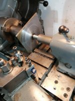
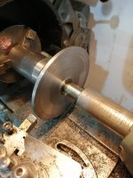
I'm currently trying to make an adapter so we can mount brake discs on the lathe, holding the disc close to the chuck so it extends into the gap in the bed and thus fits. The plate in the photo is welded onto a 45mm rod, and I'm now trying to remove any distortion and face the plate. The problem I'm coming up against is that as the cutting tool contacts the square corners of the plate, it seems to be knocking the tool back and therefore won't cut consistently across the surface - by the time it's a little way toward the centre from the corners, it's no longer cutting.

IMG_20230527_104710.jpg

The carriage is locked down and I can't feel any play in the cross slide. The tool is held firmly in the toolholder. Is the likely culprit the top slide and if so, is now a good time to drill and tap for a couple of locking screws on the top slide?
 
They look like fair questions to me, Ian! The answers are no, it doesn't need to be square (I originally thought it best, but on reflection it'd make no difference); and no, it's not flimsy (5mm thickness)*. Any thoughts on how I could reduce it to round? Just cut off the corners, then turn to round in the same way you'd turn any square stock to round? Parting-off tool facing parallel to the spindle?

I'm still bothered at how the tool gets knocked back tho, just trying to understand what's going on.

* eta - tho by the time I've finished fannying around with it, it could well be wafer thin :-)
 
If the tool is getting knock out of position then obviously it is not being gripped tight enough.
Intermittent cutting stresses everything on the lathe and so needs great caution. Avoid carbide tipped tooling as it will get the tips knocked off in a jiffy. Have the absolute minimum of tool protrusion and minimum chuck overhang.
Start from the centre outwards, drilling a small shallow relief hole in the centre first.
One or two thou cuts maximum.
If you dont need it square then cut the corners off to an octagon and then again to 16 sides and turn it circular first before facing.

Bob

PS No, do not use a parting tool in this way. A sturdy left hand knife tool will be best.
 
Chris, I have no advice to give regarding the myford, but you mention your son is hoping to get into classic car restoration and I have a bit of knowledge on the subject. Rich restorers are few and very far between. I have a cousin who has spent his life trying to make it a success. He is very good at the practical side and greatly sought after by other shops, but has never been able to make a full living from it.

Encourage the boy to multi task :D
 
I think we're going to go for the cutting-down option, Bob - fighting with those corners is frustrating and cutting it down then turning as you describe should be relatively straight forward. Thanks again.

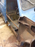
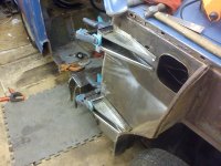
We've talked this one over at length, SB, and I certainly don't know the answer - except to agree with your last point (multi-task). We bought the Midget cheaply so he can try doing all the jobs (body/ fabrication, mechanics, electrics) and it's going well so far, lots and lots of thinking and learning. But it's pretty clear that once we add up all the costs, we won't see any money back - if we sold it, it'd be at a loss. But hopefully he will have a lovely little car. (He's now on about upgrading it for autocross :| ) I'm sure there might be a better chance of making money doing restoration of more (ie very) expensive classics, where the material costs and time aren't so different but the final outcome gets a higher price, again, I don't know. The Bantam is another project, more learning and maybe another line for him.

He's currently doing a welding course and should finish that with a decent qualification that would allow him to travel and earn good money as he goes (he wants to travel, and there seems to be a lack of such skills from what I can tell/ people tell me), and he's learning to use our lathe and mill as we go. I came across the term 'heritage engineering' recently, and think that's the way he's heading in his mind. Anything mechanical/ engine-based and pre-computer. So yes, multi-tasking, a couple of days a week working on his own projects; a few days a week working for someone else could be a solution. My advice to him has been to do what he loves and to do it as best he can, get a reputation for excellent work and go from there. His original plan was to go to university to study automotive engineering but the best part of 1.5 years studying for his A-levels in his bedroom on a laptop during covid lock downs didn't work out for him, so he's now trying a different route.

I really appreciate your thoughts - thank you SB.
 
Welding is definitely a transferable skill That will bring home the bacon anywhere in the world. Bearing in mind my 20 years working on machines in fast food outlets, I met 100's of people with degrees (mostly media studies but a lot of others as well) working wrapping burgers, never once met a welder there.
When I moved to Cyprus I still had to work, and with all my gas qualifications and engineer experience I went to several catering companies expecting an open arms welcome. Every one asked if I could weld stainless. Fail.
I can weld iron, but not well enough to trust my life on the joint and I havent welded stainless or ali since the mid 70's.
My relation lives in Belgium and has a part time computer IT job to bring in money, but his love has always been old (oops, classic) cars, and he does pay as you go work for a large restoration company there.
 
Chris, I do a bit of resto work, I look after a little Austin 7 and am working on a 1954 Austin A30 which has taken a back seat for a while until I get my workshop back to usable, it is a good multi skill challenge, and can involve a bit of wood work as well, wouldn't mind finding a midget for an engine and brakes transplant into the A30.
Austin 7.jpg
A30 door hinges plates 1.jpg
A30 door hinges plates.jpg
metal bashing.jpg

Dominic Chinea did a youtube on the Heritage Skills centre which you may find interesting as a potential avenue to explore: https://www.youtube.com/watch?v=oj9qQzkKhFs

I can Mig weld and a mate of mine is a coded welder who traveled the world, mostly in the Gulf working in the Oil industry, earned well, but terrible life style (heat was a killer)
 
IMG_20230528_143127.jpg
That's more like it. We scored the largest diameter circle, cut the corners off, then the lad crept up on the circumference on a belt sander and finished off on the lathe. Facing was then easy, and I used a HSS tool I'd made instead of the carbide tip I'd been using before, much better. Thanks Ian and Bob! Now we need to learn to mount the adapter onto a 4-jaw chuck and work on the other side.

sunnybob":2ig5vya0 said:
old (oops, classic) cars
:D In my experience, they're great so long as you don't need to rely on them, then it gets really annoying.

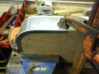
HOJ - what a beauty! And I'd not seen that link to the Heritage Skills Centre, tho we've watched the kind of work done at Bicester with interest - I think if he gets an apprenticeship, he'll try for that for sure. And funnily enough, my rudimentary woodworking skills came in handy last year when we made a couple of panels for his 'daily driver' (it only gets occasional use), and it went really well after much bending and beating and noise. Thanks.
 
We're learning to use a flycutter with an HSS bit we shaped. How often would you expect to put an edge on the tip with a diamond card, and how often to put it back on the linisher to restore the shape there? I'm not sure what's going on, but I think it's leaving a better finish after the linisher and a little honing, but soon going down hill (3 or 4 x 0.01mm passes on the longer face of a 1.5" x 2.5" block of mild steel).

I've also been struggling somewhat to get the block squared up (it's for a rear tool holder for parting) and finally realised that the cheapo parallels I'd bought aren't accurate - one is 20mm height, the other 20.02mm. I've lost count of the times we've recut it trying to get it square! We'll soon have a dice instead of a toolholder.

Oh, and Al - I've ordered a vertical digital linear scale to replace the intensely annoying one that came with the mill. Ours is exactly as you described it on your web page. :-)
 
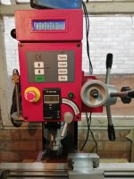
Sorry, yet another question. Al (or anyone who knows) - I'm trying to remove the control panel from the mill (Sieg SX3) to replace the dro, but with the four retaining screws out and the spindle lock removed, it only wiggles about with about 7mm gap at the edges and won't lift off any further - any idea what's holding it on? It feels like something's hanging on at the centre. Is there a knack or have I failed to release something?
Thanks.
 
Chris152":295hq1kw said:
Sorry, yet another question. Al (or anyone who knows) - I'm trying to remove the control panel from the mill (Sieg SX3) to replace the dro, but with the four retaining screws out and the spindle lock removed, it only wiggles about with about 7mm gap at the edges and won't lift off any further - any idea what's holding it on? It feels like something's hanging on at the centre. Is there a knack or have I failed to release something?
Thanks.

RTFM? there might be an exploding diagram showing why?

Bob
 
I did read the FM, Bob :-). There's an exploded diagram but I can't see anything on it that shows why it wouldn't just lift out, albeit with wires attached - which is why I'm reluctant to pull any harder, in case they are very short and I do damage that I certainly couldn't repair.
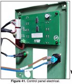
ps Here's a pic from the Grizzly manual (same machine) showing the rear of the panel once it's removed - with the spindle lock removed, I can't see from the exploded diagram nor from that pic what'd be holding it on.
Control-panel-rear.jpg
 
Have you tried fully removing the screws? sometimes there is a false step on the thread where you think its undone but it actually needs another full turn.
 
Bob - I've tried searching for the Sieg and Grizzly, people just jump past that part. Which makes me think there should be no issue, and wonder if a wire has become snagged behind something.

SB - I removed the screws completely so shouldn't be an issue there.

If someone can confirm it should now just lift out (wires attached), I'll know something's wrong and think about a way to attach the dro to the outside - it'll be ugly I suppose, but what matters is that works.

Thanks both.
 
Making sure its disconnected from the power..... :shock: :eusa-doh:
. Use a thin flexible piece of steel or plastic and gently slide it around behind the cover, to find whereabouts the problem is. If its one corner or end, tilt the lid as far out as it can go on the other side and take a picture behind it with your smart phone. You can expand the phone pic and see the actual problem.
 
Thanks SB - I've had a go at your suggestion but can't get a pic showing what's going on, the snag (or whatever it is) seems to be just about the centre of the panel which leaves very little space at the edges.

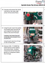
I thought I'd found the answer buried in the instructions for fitting an extra to the lathe - lower and lock the spindle (point 17 in the pic) - and got all excited. But it seems to have made no difference :-(
Control-panel-removal-guide.jpg
 
That appears to be the problem.
Start with a fresh set of eyes, ask someone else to go through the steps with you. When I am stuck I get my wife to watch, and I explain every step. Sometimes I realise what I've done wrong as I'm explaining it, sometimes she asks the 64,000 dollar question. :eusa-doh:

Make sure you have obeyed fig 16.

Is there a bottom stop on the quill that you have not released to its maximum depth?
Is the fine feed lock knob actually locking the quill at its lowest point?
 
sunnybob":1g0hn40r said:
Is there a bottom stop on the quill that you have not released to its maximum depth?
Brilliant, Sunnybob! That was exactly the issue, the stop wasn't allowing the spindle to reach its full depth - I've not touched the depth stop since we bought the machine, and it didn't even enter my mind!
Thank you so much for your perseverance, now we can get on with the actual job in hand.
 
Thanks for the link Al - I was going to complain that that set of instructions also didn't say to lower the spindle as far as it'll go, but it does say to disconnect the dro bracket and lower the beam, which I guess has the same effect? ie, it's the dro beam that was causing the panel not to lift off?

Anyway, enough of that - now on to the tricky bit (as if thus far wasn't already tricky enough, at least for us), trying to find the best way to attach the new dro so it fits properly (Arc didn't have the same one you used in stock, so I went for the other they have).

Hope you had a nice holiday!
 
I've not uploaded a video to the site before, hopefully it'll work...

I've been doing a fair bit of boring yesterday and today and the noise of the lathe started to get on my nerves. There's a rhythmic rattling sound coming from the motor drive pulley, sometimes I think it's worse than others. With the belt disconnected, the motor runs quietly; with the belt loosened more, it's worse (and it sounded like I could hear gears rattling). So I've put it back the way it was and it's back to 'normal'. The pulleys seem to be aligned properly. The rattling sound is far more tinny in the video than I hear it while working, but maybe that helps identify the problem?

Also in the video, the clutch plate is off-centre, but seems to work fine. Is that an issue, too?

https://youtube.com/shorts/i7xrgzE7un8?feature=share

Thanks for any thoughts.
 
https://www.youtube.com/shorts/mTD0-kl5Few

Much, much better. I've removed and re-tightened that pulley several times since we got the lathe, this time (after your post) I cleaned the channel and key, which had some oil on the contact surfaces, and the result is a vast improvement. So there's no question, it was indeed the pulley, tho there's still a slight ticking sound.

When the motor finally slows right down to stop, that slight ticking is still clear - might that be the motor bearings, as you mentioned many posts back?

Thanks Bob.
 
That's great - thanks again Bob. I'll keep an eye on the pulley and if it starts again, take it off and give it a thorough cleaning.
 
Right, yesterday evening I needed to get the lathe up to a higher speed again, turning the outside of a longer bar using the leadgear. It's not the first time I've used the change gears but, what a palaver. So, I think I'll convert it to 3 phase with an inverter. I've been watching a chap on YT who seems to have a good handle on the conversion for an ML7, and I've found the same kit he used so should be able to follow without too much difficulty.

This is the motor: https://www.ebay.co.uk/itm/114401319441
My question:
Top speed on our lathe is 2105; speed on 4 pole is 1400, 2 pole is 2800. So far we've not gone beyond the 600 that the slow pulley gives and that seems fine for now.
From what I've read, it's ok to run the motor at 60 Hz and increase the 4 pole speed to about 1700. Is that correct, and if so, given that it doesn't look like we'll be doing much at high speeds/ narrower diameters, would 4 pole be a better bet for us?

I guess my question in short is, is there any disadvantage in using a 2 pole motor compared to a 4?
 
I dont follow your argument. Changewheels have no effect on spindle speeds so why did you regard as palaver to change spindle speed?

If you want to avoid changing belts for everyday turning jobs then fine
A four pole motor and a vector inverter running from say 20hz to 100 hz will do most tasks with a median belt setting.


Unless you spend out on a quick change gearbox then you will still need to flip change wheels between fine feed and the screw cutting pitch needed for each job.
 
Yes, you're right - my thinking was wrong. Thanks for the correction. I suppose what I really want is an electronic lead screw but that's beyond me.
 
Yes, I've watched a number of them including the Clough one, but still feel it's not something I could confidently tackle. When someone releases a plug and play version for a decent price I'll definitely go for it - in the meantime, if a quick change gearbox come up at the right price, I may go for that.
 
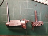
We're looking to build a wheeling machine and need to decide whether to buy or make the rollers. These two tools came with our lathe when we bought it, I seem to remember one was for cutting spheres, not sure which, let alone how you use it or if it could be used for making rollers of various radii (we're thinking about 2" wide rollers of radius 3" - 8").
Any thoughts what they are and if they could be used for that purpose, or just for small spheres?

IMG_20231124_212336_edit_144284772383711.jpg

ps Here's a link to the kind of thing we want to make:
https://www.frost.co.uk/ew-anvil-set-english-wheel/
 
The ball turning tool you have is nowhere near big enough for 3-8 radius.
You need the tool tip to be 3-8" from the swiveling axis for that to happen and in anycase without a lot of extra tool making I cant see it fiting on a small lathe like the ML7. If you can buy rollers that would be the most cost effective route if the budget is tight and you are time rich then maybe make tool to do it.

Bob
 
Back
Top