• Hi all and welcome to TheWoodHaven2 brought into the 21st Century, kicking and screaming! We all have Alasdair to thank for the vast bulk of the heavy lifting to get us here, no more so than me because he's taken away a huge burden of responsibility from my shoulders and brought us to this new shiny home, with all your previous content (hopefully) still intact! Please peruse and feed back. There is still plenty to do, like changing the colour scheme, adding the banner graphic, tweaking the odd setting here and there so I have added a new thread in the 'Technical Issues, Bugs and Feature Requests' forum for you to add any issues you find, any missing settings or just anything you'd like to see added/removed from the feature set that Xenforo offers. We will get to everything over the coming weeks so please be patient, but add anything at all to the thread I mention above and we promise to get to them over the next few days/weeks/months. In the meantime, please enjoy!

Mark's Workshop/Garage

That looks like back breaking work to me Mark. Shame it has to come up as it looks in good nick from here. Hope you have some heavy machinery to help. Good luck.
 
Andyp":332og4f7 said:
That looks like back breaking work to me Mark. Shame it has to come up as it looks in good nick from here. Hope you have some heavy machinery to help. Good luck.

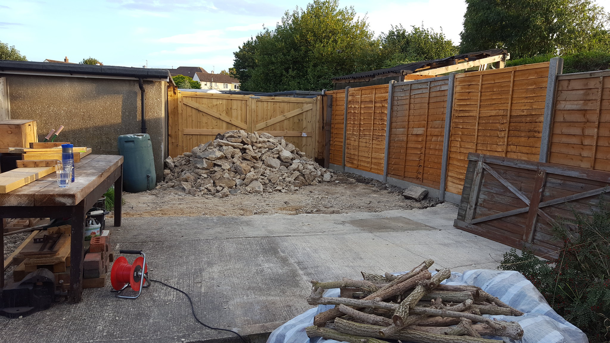
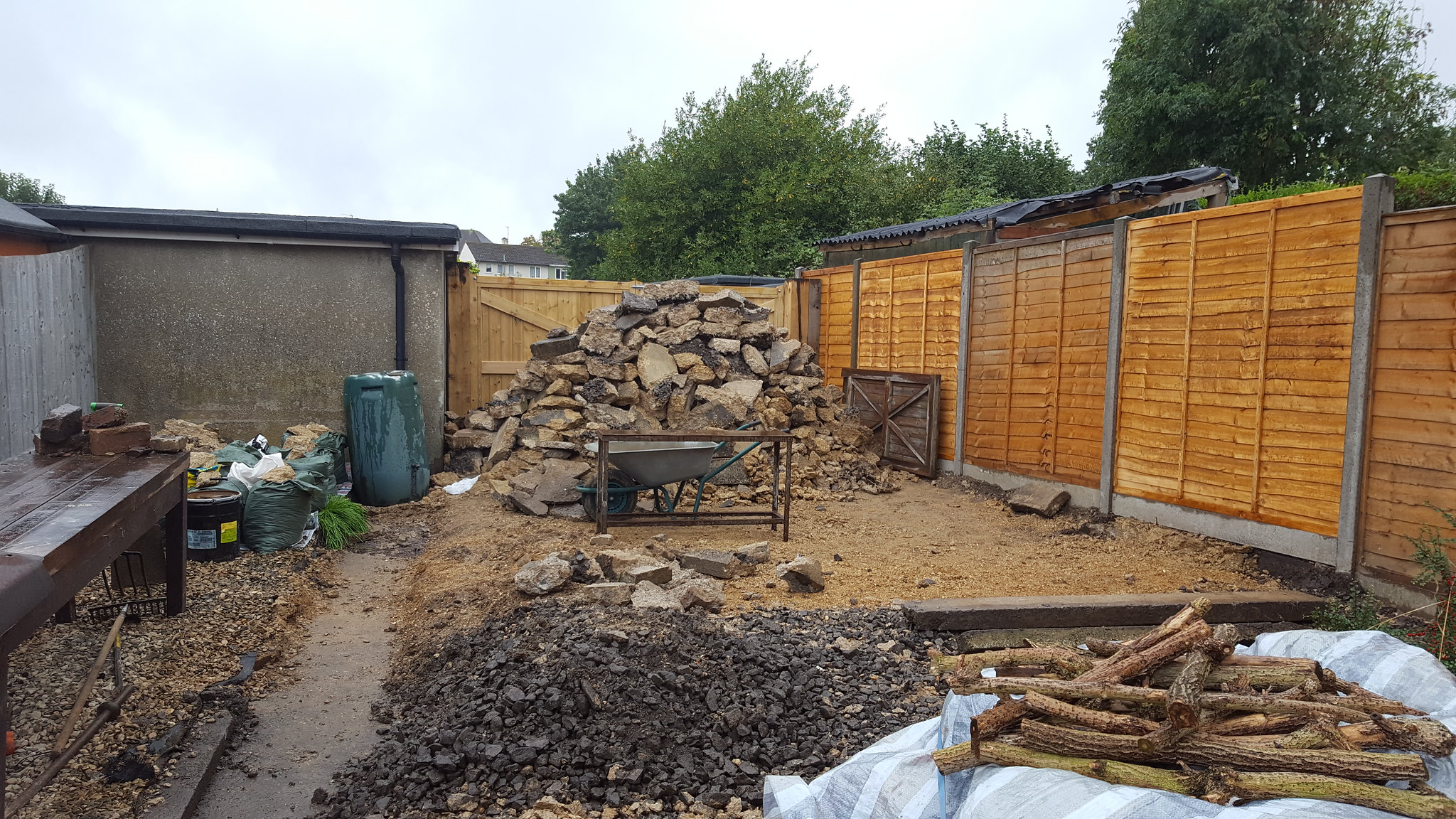
Indeed, I had a heavy breaker that weighed ~30kg and that was the hardest part - lugging that thing around! Although it did do the job, made light work of breaking up the concrete. Rain stopped play just after lunch on Sunday with the job pretty much done. Among other things (is it just me or was it standard practice years ago to discard all manner of things under concrete?!) I discovered that the concrete path that goes up the garden actually continues under the concrete. This stills needs removing but it is wafer thin, incredibly weak and shouldn't take long to clear.

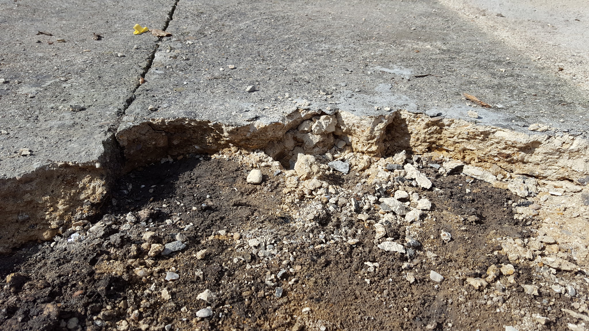
There were many reasons for removing this concrete, firstly it was in the wrong place! It had no DPM! It was quite a bit higher than ground level, adding unnecessary height to any structure if I were to build off it. It was in poor condition - it was 'laid' in three sections, with the section nearest in the photo being by far the best bit - the two sections beyond were really poor. The better section had a sub base (the dark stone), however the two other sections had no sub base, just a thin covering of ballast and crumbly, sandy concrete of varying thickness.

One of the thinner parts of the rough sections, approximately 2 inches thick. Notice the absence of any sub base and the clay soil immediately under the concrete!

36186610684_e165b6594c_k.jpg


End of day one

36851013332_73c3b8b2bc_k.jpg


At this point the rain become too much on day two. One BIG pile of rubble! You can clearly see the path that still needs removing. Also on the right, a couple of large concrete posts/beams that were unearthed!

36851020582_146f696e9d_k.jpg
 
Little update - site cleared, well it was! There is a load of compacted scalpings and sand there now, concrete should be going down this week. Then, hopefully things will start moving a little quicker!

My mind is currently occupied by thoughts around the framing. The walls should be straight forward enough, it's the roof that vexes me, more precisely the gable above the big doors.
I have, however a plan. A bit of a twist on Mike's earlier advice (below).

Mike G":3v2209vh said:
Given the loadings on a ridge beam are almost entirely vertical, (if the walls were forced apart by the un-tied rafters the ridge beam would be dragged directly downwards) one has to resist that vertical force. Now, this is most easily done with a post. However, if we are relying on the rafters at the gable (as we would be at the gable above the lintel over the big door opening) to hold the ridge beam up, we need a suitable junction between the rafters and the ridge such that an elephant sitting on the ridge board at that end wouldn't push the ridge down out of connection with the rafter ends. There are lots of ways to achieve this. One of them is to have an upside-down birdsmouth, so that the ridge beam physically sits on part of the rafter. Unfortunately, given your timber sizes, this wont work.

What I suggest is this:

XsbrXKf.png

Bolt a piece of 195x45 hard up underneath the ridge beam at the gable rafter location.

Further, as you don't want to be throwing load onto the lintel below, the end rafters should be doubled up, and nailed together (alternately top and bottom edge, max 500 C's). This is going to complicate your OSB lining somewhat.

The other end can be dealt with as per mine, with a post under the ridge beam. This should be directly above a stud in the wall (in other words, when you set your wall out, you need to put a stud exactly in the centre). The rafter only need be a single pair, not doubled.
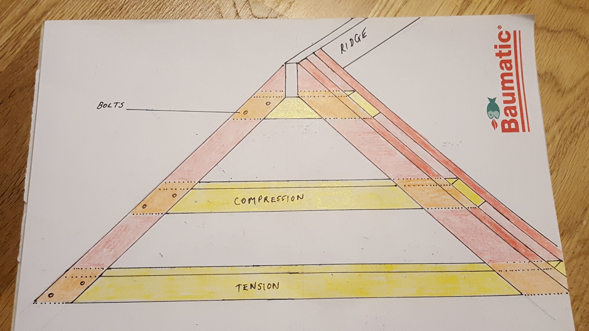
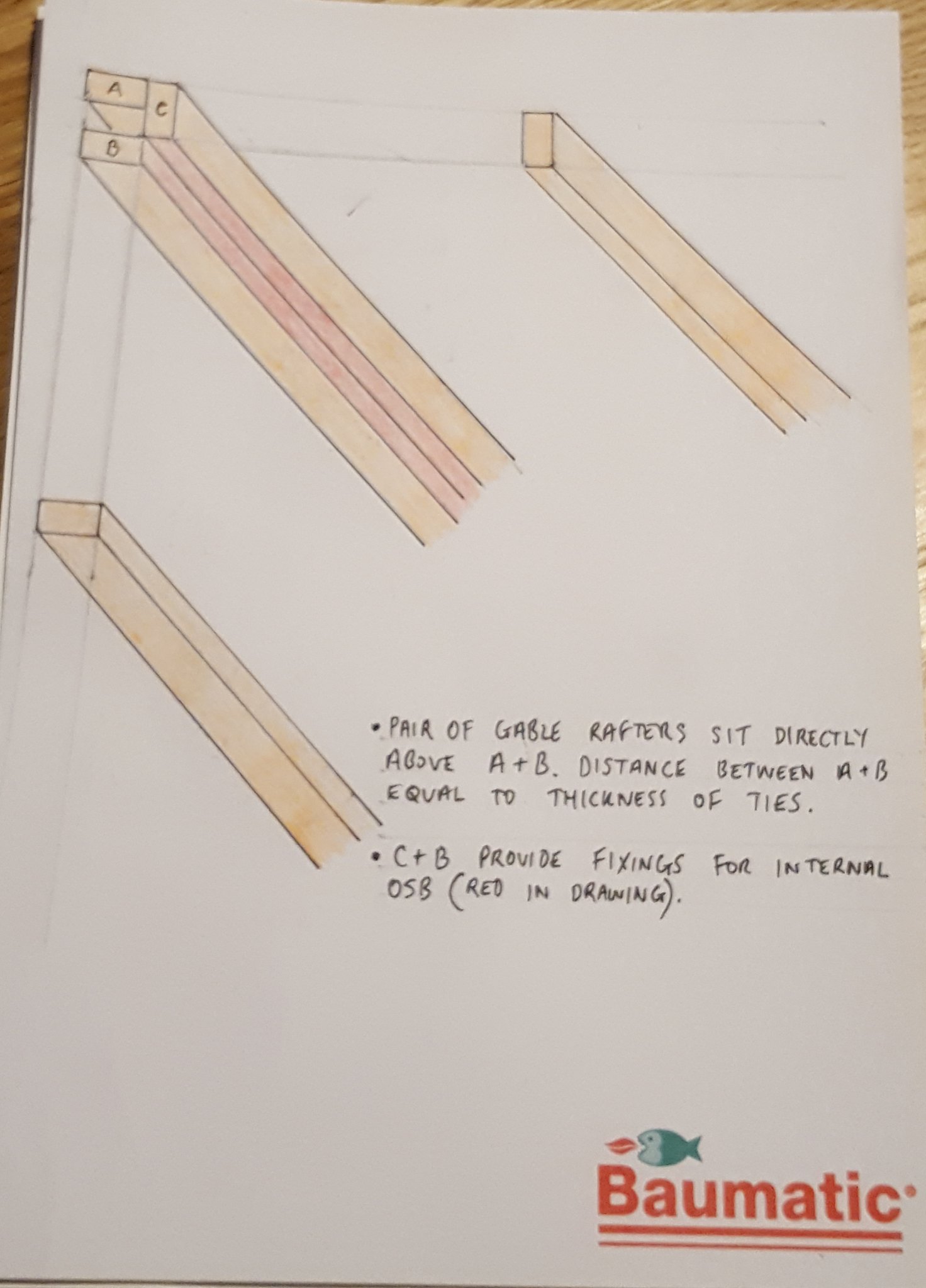
What I'm thinking is two pairs of rafters and sandwiched between them two/three ties. One hard against the underside of the ridge beam, one mid way along rafters and one towards the bottom of the rafters.
Why? Well this strikes me as being an incredibly strong 'A frame' to support the ridge.The ties also provide a face to mount vertical timbers which, as well as adding strength they will provide fixing points for the FE boards to (The vertical timbers when mounted will be flush with the outer pair of rafters).This arrangement also fits nicely with the corner detail on my wall framing plan.
Big question is however, is this adequate? Will it work? Opinions please kind people!..

I've made use of the kid's pencils in an attempt to make more sense (drawings not to scale or anything)! -

37320156360_c67d2421a6_k.jpg


Wall framing corner detail, viewed with wall plates removed for clarity. Each rafter is directly above a 'stud'
37320149950_6bc6c0e078_k.jpg
 
Mike G":24hxpue2 said:
"Is this adequate?"

Yes. More than......

I was hoping to hear from you Mike :D I also had a suspicion it would be deemed overkill, but belt and braces is my style! ;)

I thank you (once again) :obscene-drinkingcheers:
 
A well over due update...

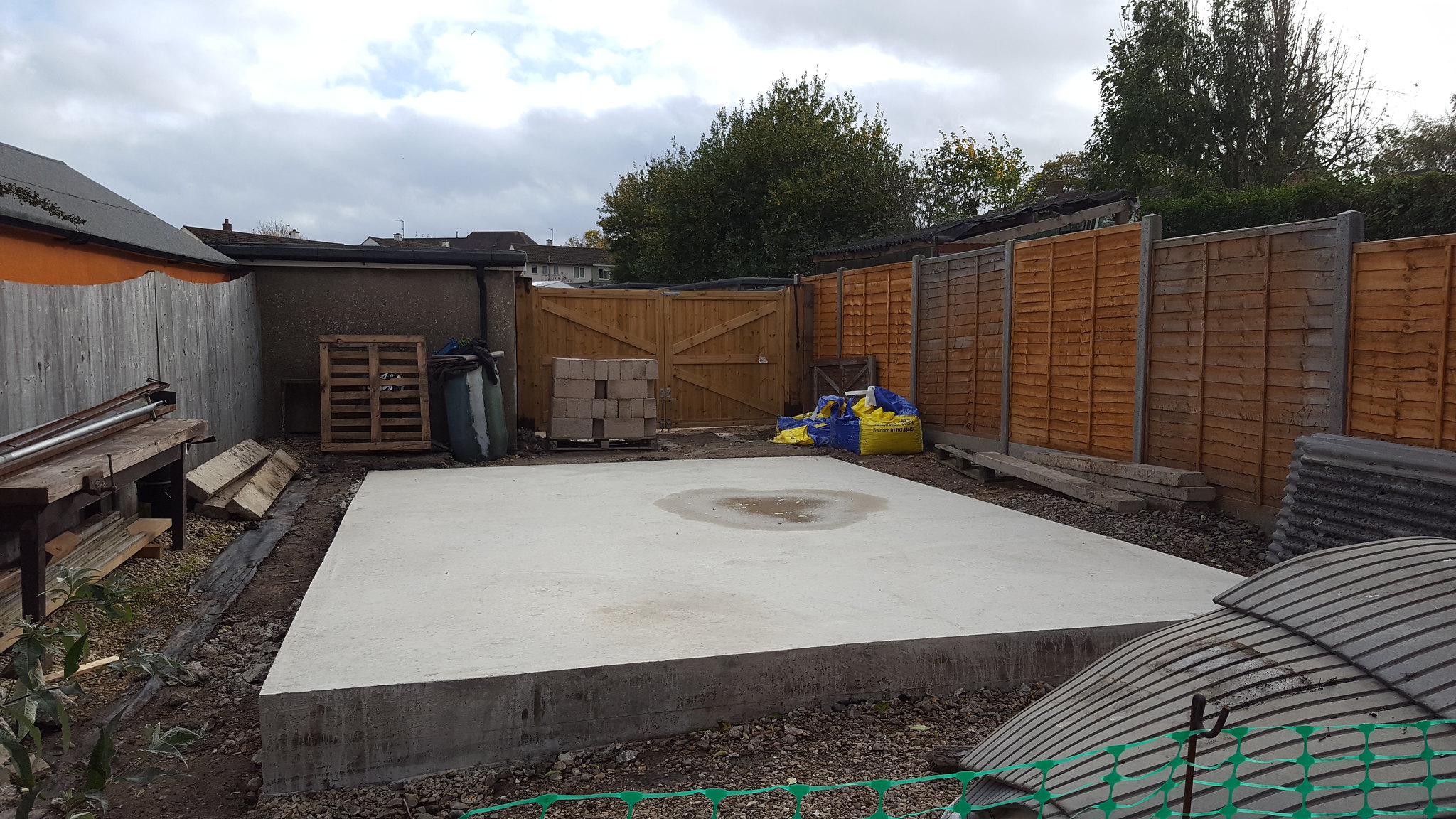
I have concrete -

38239174482_ee48f09abe_k.jpg


I had some Albanian builders in to do this (the cheapest by some margin), they worked hard and got it done quickly. However there are a couple of minor issues, but I guess you get what you pay for and all that. With hindsight I wish I had actually done it myself.

I have also laid some blocks -

24399986948_eaac80c19c_k.jpg


I took my time getting the string lines set up, so they're straight and square, just they're not pretty. I do plan to paint them at a later date though. What really surprised me is how much hard work it is! Spending the whole day working at ankle height meant my back and legs suffered!

Currently putting together an order for timber then things will hopefully really start moving along (plenty more photos too :D ).

Mark
 
Now, I need some advice from you clever people :P

As I said in my last post I am putting together an order for the timber framing and I just wanted to check a few things;

Double studs for the door and window apertures?

Ridge beam - I'm thinking 9'x2' for a vaulted ceiling and span of ~6.5m?

Rafters - by my calculations I will have 6162mm between the 'first' and 'last' pair, which means another nine pairs at ~616mm centres. Would this be ok? Or would I be better off with 10 pairs at ~560mm centres?

As always, all input very welcome and gratefully received :text-thankyoublue:
 
9fingers":1jgvlh21 said:
Looks like that slab won't be going anywhere!

A great start!

Bob

Hopefully! The photo is a little deceiving - the ground surrounding *that* corner is a lot lower, so the heel of the concrete there is subsequently a lot bigger than on the other edges!

The 'middle' is 150mm thick with steel mesh, just in case! ;)
 
Remind me what's going on your roof? This will make all the difference to your rafter spacing.

Double studs?..........Sort of. One is a full height stud, and then inside that is the cripple stud which supports the lintel. So yes, there are two bits of wood side-by-side, but technically only one of them is a stud. If you have big heavy doors consider adding extra noggins either side of the opening to help stiffen everything up.
 
Looking good, Mark. My legs and back shared your pain!!

Advice given to me was that rafters, given appropriate width and thickness, should be a common denominator fraction of the width of the sheathing apart. By that, if the sheathing is coming out of 2400 x 1200 sheets, the the rafter should sit at 600mm centres, apart from the two end ones.....I think.

That way, you should never have to cut a sheet width to fit onto the rafters.
 
Before adopting a non standard pitch for your timbers, work out some details of your cladding for both walls and roofing and set the pitch to be convenient for the cladding. Usually 600mm (or 400) centres works well and just put an odd one in to make up the final dimensions.

Usually the rafters will sit over vertical studs to transfer the roof load onto the dwarf walls. Other wise you might need to beef up wall plates unnecessarily.

Bob
 
Mike G":3s24cpzh said:
Remind me what's going on your roof? This will make all the difference to your rafter spacing.

Vaulted ceiling, with a structural ridge beam. Both gables being a truss, because a king post isn't an option - the big door and a window will be directly under ridge at either end. Truss design as per my earlier drawing -

37320156360_c67d2421a6_k.jpg


Mike G":3s24cpzh said:
Double studs?..........Sort of. One is a full height stud, and then inside that is the cripple stud which supports the lintel. So yes, there are two bits of wood side-by-side, but technically only one of them is a stud. If you have big heavy doors consider adding extra noggins either side of the opening to help stiffen everything up.

I get you! That's what I meant - basically copying the way you did the apertures on your build!

Nice tip about the noggins either side of the big door - thanks. As the wall plate will be the top of the big door aperture (no cripple studs), is there any point doubling up the studs either side of the big door? I plan to sit the lintel (doubled up 8x2s, one being the bottom chord of the truss) on the wall plate.
 
Yep, double them up anyway. You neither want a door to hang on just a single stud, nor to shut against a single stud. There's too much movement.

I meant what is your roof covering going to be? Tiles, rubber, Onduline, felt, crinkly tin.........
 
Thank you Bob and Malcolm - I do plan on the wall frame studs being set out to minimise cutting of OSB for the internal cladding (external will be FE boards in continuous lengths so stud spacing not so critical for those. However it didn't cross my mind to think about how the rafter spacings fit with the Onduline roof sheets I plan to use.

More to frazzle my head with....

Edit: I guess this answers your question Mike - Onduline, with the view of slates at a later date (when the Onduline gives up).
 
spearos":1cmo0ig2 said:
However it didn't cross my mind to think about how the rafter spacings fit with the Onduline roof sheets I plan to use.

There is a reason why I didn't think about it - I'll be using purlins to mount the Onduline, so the the rafter spacing doesnt necessarily need to be matched to Onduline sheet size.... I think :eusa-doh:

Edit: But then there is the mounting of the internal OSB to the underside of the rafters..... I should shut up, and just think about it!!
 
Mark,

I found that I couldn't visualise my thoughts. So I learned to use Sketchup. You are drawing your some of your ideas, and other guys use different CAD apps.

The stages you've just gone through, the rafters, the Onduline, the purlins, the wall frames and the vertical studs, would freak me out, if I didn't have a way of recording the idea.

So I drew my ideas in Sketchup, and if they didn't fit, I'd find a way to make them fit by drawing/modelling them.

I would advise you to draw your ideas to find out what doesn't work. that way, you'll find out what does work. It doesn't really matter what app you use, whatever works for you.
 
Firstly, you don't have a choice if you only have a single plate: your rafters must sit above your studs. However, if you double the top plate, your rafters can go anywhere. The usual practice is to space them according to set centres (400, 600, or occasionally 450), and have a narrower gap at one end of the roof. This is because there is usually some sheet material involved. In your case, you'll be lining the underside of the rafters with something. Generally, boards are 1200 x 2400, so you space the rafters to suit that. Sometimes you find that the board is imperial (1220 x 2440), and so you might space them out accordingly.
 
9fingers":2sl1ukqo said:
OK but maybe careful rafter spacing will make insulation easier too

Worth thinking through the steps now rather than later?

Bob

Exactly Bob, hence airing my thoughts/quandaries on here and getting the opinions of kind, experienced people like yourself :obscene-drinkingcheers:

Malc2098":2sl1ukqo said:
Mark,

I found that I couldn't visualise my thoughts. So I learned to use Sketchup. You are drawing your some of your ideas, and other guys use different CAD apps.

The stages you've just gone through, the rafters, the Onduline, the purlins, the wall frames and the vertical studs, would freak me out, if I didn't have a way of recording the idea.

So I drew my ideas in Sketchup, and if they didn't fit, I'd find a way to make them fit by drawing/modelling them.

I would advise you to draw your ideas to find out what doesn't work. that way, you'll find out what does work. It doesn't really matter what app you use, whatever works for you.

Wise words and I appreciate your advice. However I do have a great big folder of sketches, notes, print offs etc etc. It seems I spend every waking hour thinking about my build and mentally building it.
I did have a play with sketch up but for me it meant a lot of time learning the software, time that I really do not have at the moment.

Mike G":2sl1ukqo said:
Firstly, you don't have a choice if you only have a single plate: your rafters must sit above your studs. However, if you double the top plate, your rafters can go anywhere. The usual practice is to space them according to set centres (400, 600, or occasionally 450), and have a narrower gap at one end of the roof. This is because there is usually some sheet material involved. In your case, you'll be lining the underside of the rafters with something. Generally, boards are 1200 x 2400, so you space the rafters to suit that. Sometimes you find that the board is imperial (1220 x 2440), and so you might space them out accordingly.

I will be using OSB to clad the underside of the roof and I know my preferred supplier's OSB sheets are 1220. So as per your advice I will set the rafter centres to suit, with a narrow gap at one end, where the trimmed OSB sheets will go.

Could I please have your thoughts on the suitability of a 9x2 ridge beam please Mike?
 
9x2 won't span 6.5 metres. You'll struggle to even find a piece that long, for a start.

No, you'll either need a couple of ties to help it out, or make use of a principle truss at the midpoint, halving the span.
 
Mike G":2kkfs8uo said:
No, you'll either need a couple of ties to help it out, or make use of a principle truss at the midpoint, halving the span.

Would collar ties suffice? Fixed hard up against the underside of the ridge (as per your earlier drawing)?

Correct me if I'm wrong but a principle truss would severely restrict head room for raising a vehicle?
 
spearos":2hkkzgah said:
Mike G":2hkkzgah said:
No, you'll either need a couple of ties to help it out, or make use of a principle truss at the midpoint, halving the span.

Would collar ties suffice? Fixed hard up against the underside of the ridge (as per your earlier drawing)?

Correct me if I'm wrong but a principle truss would severely restrict head room for raising a vehicle?

No, collar ties aren't going to help much in this situation. A principle truss could have a raised tie, but a third of the way up the rafter length is about the highest you can go without getting an engineer involved. Bob's right. We're into RSJ or Glulam territory if you want a vaulted ceiling with structural ridge 20 feet long, and they will need designing by a structural engineer.

My earlier drawing related to gable with a big opening in it, lined with OSB. That solution can't be applied along the whole roof.
 
Thank you Bob and Mike.

It seems I have been incredibly naive. Doubts have even crept into my head whether I should be attempting something like this. I feel overwhelmed. I sincerely appreciate the patience of you guys - what with all my questions and lack of knowledge/experience.

I will push on though...

My immediate reaction is that I do not want to go down the structural engineer route, I imagine it will add significant cost to the build as well as holding up the build further.
So, I am exploring the principle truss idea and how much head room that would give me. With regard to the max 'height' of the raised tie being one third up the rafters, is this measurement from the birdsmouth plumb to the centre of the tie?
 
The "third" is only a rule of thumb. If you take the height of the ridge (underside) and subtract the height of the top if the wall plate and divide that by three, you will be about right to get the height of the tie.
Using the principle of similar triangles, that will put the tie 1/3rd of the way along the rafter too.

You might get away with it a smidge higher (40%) but the rafters might have to go up a size so a lot more timber for 100-200mm more height.

Bob
 
9fingers":3j3fj3m7 said:
The "third" is only a rule of thumb. If you take the height of the ridge (underside) and subtract the height of the top if the wall plate and divide that by three, you will be about right to get the height of the tie.
Using the principle of similar triangles, that will put the tie 1/3rd of the way along the rafter too.

You might get away with it a smidge higher (40%) but the rafters might have to go up a size so a lot more timber for 100-200mm more height.

Bob

So if for example underside of ridge to wall plate is 900mm, would that mean 300mm from wall plate to the bottom edge of the tie, the centre of the tie, or the top of the tie?
For this example if the measurement is to the bottom of say a 200mm tie, I would gain 300mm headroom. However if the measurement was to the top of a 200mm tie then i would only gain 100mm headroom.
 
spearos":kc2r873y said:
9fingers":kc2r873y said:
The "third" is only a rule of thumb. If you take the height of the ridge (underside) and subtract the height of the top if the wall plate and divide that by three, you will be about right to get the height of the tie.
Using the principle of similar triangles, that will put the tie 1/3rd of the way along the rafter too.

You might get away with it a smidge higher (40%) but the rafters might have to go up a size so a lot more timber for 100-200mm more height.

Bob

So if for example underside of ridge to wall plate is 900mm, would that mean 300mm from wall plate to the bottom edge of the tie, the centre of the tie, or the top of the tie?
For this example if the measurement is to the bottom of say a 200mm tie, I would gain 300mm headroom. However if the measurement was to the top of a 200mm tie then i would only gain 100mm headroom.

Generally I'd take the reference from the centre of the tie. So with your example an increase of 200mm.
But the tie is in tension and possibly does not need to be anything like 200mm deep.
In extremis you could make it a steel rod 20-25mm diameter?

My shop has a pitched roof at 30 degrees and 10m long. 100 x50 rafters at 600mm pitch each with ties also 100 x 50 about 1/3 up. Building width however is only 3m.

Bob
 
Morning Mark

My immediate reaction is that I do not want to go down the structural engineer route, I imagine it will add significant cost to the build as well as holding up the build further.

How much would it cost for peace of mind, especially if you're thinking of adding a hoist to it?

You can also take off the cost of the timber you won't need and have the benefit if a vaulted ceiling.

Once the steel has been specified, you could probably get it delivered before you are ready to fit it.

I'd think about it if I were you.

Cheers

Dave
 
A RSJ would certainly work in that situation but you would also have to beef up the end supporting rafters and the end vertical studs as they would be acting as pillars and have to support more load.

Rod
 
I have been going over and over this in my mind today and I'm still not keen on the RSJ etc. I think going down that route would further complicate the build/design and most importantly slow the build down further. Without going into the reasons, I need to get things moving. It would also stretch my inexperience even more! :lol:
I appreciate the advice, I really do, but I think if I can keep ~2.5m headroom, a principle truss is the way forward.

With a pitch of 22.5 degrees, a wall plate height of 2.3m and the building width being 4.5m, I calculate the underside of ridge to wall plate measurement being ~900mm. With this in mind, a 150mm raised tie, one third up the rafters (300mm above wall plate) would give 2550mm head room.
Question is would a 150mm tie be adequate? - I'm thinking of a truss design in the middle of the building (halving the span of the 9x2 ridge beam) that has doubled up rafters with a raised tie (6x2) and a collar tie (8x2) sandwiched between them.

Help me please! :eusa-think:
 
A bit of progress to report :D

I've decided on the roof design. At one end I will have rafter ties at wall plate level, raised ties at the other end and a section in the middle with no ties.
The ties at wall plate level will be on three rafter pairs (covering ~1.2m). They will be above where I plan to have a work bench etc (extra head room not needed). Once boarded this will give me a decent storage area above benches etc and also somewhere to mount lighting for the bench.
The area with no ties (~3.6m/four rafter pairs) will give me a work area with unrestricted head room, enough to raise one end of a tall vehicle substantially.
The area of raised ties (~1.7m/five rafter pairs) will still give decent headroom at ~2.5m and allow storage of long/awkward stuff.

I'm planning on using 2x8 for the ties. Which for a loading of no more than .25kN/M² the max span is a touch under 4m. I will be careful (weight-wise) with what I store in the storage offered by the ties so I'm happy with ties of this size... Unless I'm told otherwise! :lol:

As for actual physical progress, it's been slow. Only having weekends (with short days and awful weather!) and with other commitments time has been limited.
However, I have put together three of the six 'frames' - the plan is to make six frames, the ends of the building being single frames and the long side spans being made in two frames each.
The three frames I've made each have a window or door so have been a little more complex, The remaining three frames are straight forward and shouldn't take too long.

The first frame I made unassisted, it was slow and once made I couldn't move it (timber was wet)! So I decided to cut all the studs and base/top plates.

24919025408_c62d038c1b_k.jpg


I remember Mike G saying that the cut ends of timber are the most vulnerable, with this in mind all cuts have been treated. A bit over-kill perhaps but I got a great deal on the preservative and I think for the short time involved in applying the treatment, it is worthwhile.
Incidentally, I was surprised at how little the pressure treatment penetrated some of the timber. Looking at the photo, is this normal? Or is my timber supplier just supplying a poor product?

Still thinking about the roof, when I get there I plan to use the 'step out method' for marking the rafter cuts.
It seems straight forward enough and to keep things simple I will use a 5/12 pitch which at 22.62º is marginally more than the planned 22.5º.
Or, can someone recommend an easier way or point me to a useful guide or 'how to'?

While I'm talking about rafters I've read that the plumb cut of the birds mouth should be no more than 1/3 of the rafter depth, this doesn't worry me as I'm using 2x8 rafters so there's plenty of material. However for my application I'm thinking the seat cut can dictate the plumb cut. But, what should the seat cut be? Perhaps around the same as the wall plate - 96mm?
 
Apart from the technical stuff, of which I have no idea, it sounds great!!
 
No, that penetration is normal Mark. It is a barrier, no more.

As for birdsmouths, I tend to make the plumb cut the depth of the plate if there isn't a good reason to do it differently.
 
Thanks guys :D

So tomorrow I'm braving the cold and I hope to have all the wall frames up. My plan is to sit them on wedges (with no mortar) and get them all braced level and square - I envisage positioning them as being a bit of a pain, especially because of the internal boarding detail I'm going for. Besides, I don't think the weather conditions will be conducive for mortar setting.
The mortar bed I will do when it warms up... which I'm led to believe could be a while - signs are we could be in for a long cold winter. Now wouldn't that be typical when I'm building a workshop!!
 
I seem to recall a year ago I started laying the bricks for my plinth. Had to look at the Met Office website every few hours to predict whether it would be 'warm' enough to mix mortar!
 
Back
Top