• Hi all and welcome to TheWoodHaven2 brought into the 21st Century, kicking and screaming! We all have Alasdair to thank for the vast bulk of the heavy lifting to get us here, no more so than me because he's taken away a huge burden of responsibility from my shoulders and brought us to this new shiny home, with all your previous content (hopefully) still intact! Please peruse and feed back. There is still plenty to do, like changing the colour scheme, adding the banner graphic, tweaking the odd setting here and there so I have added a new thread in the 'Technical Issues, Bugs and Feature Requests' forum for you to add any issues you find, any missing settings or just anything you'd like to see added/removed from the feature set that Xenforo offers. We will get to everything over the coming weeks so please be patient, but add anything at all to the thread I mention above and we promise to get to them over the next few days/weeks/months. In the meantime, please enjoy!

Mike builds a teardrop (Electrics)

The PTFE (which is the same thing as Teflon) strips suggested by @Malc2098 sound like a good option to me.

Another idea (that may not work): how about carefully (perhaps with a fine paintbrush) oiling the groove. The oil might prevent the epoxy from sticking and allow it to be peeled out. You'd have to test it on a bit of scrap of course as I don't know for sure that the oil would prevent the epoxy from sticking.
 
@Mike G ... how are the seal strips being fixed into the grooves?

I think this information may help others to come up with something? You've mentioned considering using putty but rejected because of the oil possibly staining the sapele timber.

I've never worked with fibreglass so have no experience of what is involved...

*I've put your question/text into Google which has come up with some suggestions plus steps for going about doing it. Would you like me to post it here?
 
Last edited:
Hi Mike

There are a number of plastics you could use including polypropylene which are "slippery" I have some scrap lengths of that as I used it a lot of it for wall cladding in food prep areas for a number of businesses. I could certainly send you strips which would I suggest want to be wide enough to protrude and grip to pull out however....it's nominal 3mm thick but I'll check with a micrometer later.

You could really use any plastic or even metal strip as long as you waxed it well first or maybe thinner (even ply) and fit a strip of masking tape or parcel tape each side. The tape would be left behind to be scraped off. Even stiff cardboard perhaps if it's oiled or waxed would probably do the job. Rubber sheet like car mats iff smooth? there must be loads of possibilities with a bit of lateral thought.
 
There are a number of plastics you could use including polypropylene which are "slippery" ......

That was my first thought, Bob, but I worry that if anywhere isn't a really tight fit that the epoxy will run down into the groove and give me an almighty headache. Cardboard sounds obvious, too, but if it absorbed the epoxy, again, I could have a problem.
 
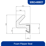
A "V" is pushed down into the groove. Here's the profile. It's the bit at the bottom which squeezes into the groove:

View attachment 57177
Thanks.

Google has suggested 4 possible methods to look at Mike. I know not everyone likes the results that come up if using an AI program but these may be worth considering? As I mentioned earlier, I put in your text from your comment:
20260803_130632.jpg20260803_130647.jpg20260803_130656.jpg
 
That was my first thought, Bob, but I worry that if anywhere isn't a really tight fit that the epoxy will run down into the groove and give me an almighty headache. Cardboard sounds obvious, too, but if it absorbed the epoxy, again, I could have a problem.
A couple of your magic mix could solve the absorbtion issue maybe but getting the whole strip tight might be fiddly. What about silicone strip, something like this on Amazon? I haven't looked but there must be others.
 
Yeah, that's a thought. It should wedge in quite tightly.

I have high hopes for plasticine, but if that doesn't work, I'll give this a try.
 
How expensive are those seals? Could you you trim the seal to just the bit that fits in the groove, then epoxy, remove the seal and fit a new complete one?
Interesting thought. It's actually expensive stuff to buy in the length I need, but dirt cheap if you buy way too much. So there may be some mileage in your idea.
 
I've used polythene to prevent sticking in the past. Could you wrap something in polythene then push it into the groove. After the epoxy is set cut the polythene at the top, pull out the infil strip then pull out the polyhene - or all in one if it comes out easily.

Something that would be easy to try on a test piece before committing to it. Polythene layflat tubing is available and cheap then you need a thin strip of wood or whatever... if the idea passes testing :)
 
I've already got some Playdough here. I'll give that a try later. I worry that it may not repel the epoxy quite so well.
 
Interesting thought. It's actually expensive stuff to buy in the length I need, but dirt cheap if you buy way too much. So there may be some mileage in your idea.
I’ll let you know later @Mike G , I may have some gash pieces of Aquamac 21 or 63 seals that I had to pull out of a job, in a box somewhere, If I can find it!.
 
The rubbery foam that’s used for pipe insulation, cut up on the bandsaw to the correct size would push in nicely and don’t think it would stick to appoxy
 
So that's what you do in your spare time Mike :ROFLMAO:
:ROFLMAO: The grandkids have just left.....

I've spent much of the last 3 weeks putting the lids back on Playdough pots. I didn't think that it would be for my benefit.
 
Thinking through what I said earlier my approach would be to cut strips of suitable cardboard maybe a inch wide, roll out some parcel tape sticky side up and place the cardboard strips edge down the centre of the tape then fold the tape up easch side. Lightly wax the tape and likewise the groove in the timber and push it in tight. I'd be looking for cardboard maybe 2.5 - 3mm thick which is common and pinch it a little so its a tight fit.

Very cheap solution which needs testing first but I cant see any reason why that wouldn't work and certainly won't stain the wood.
 
:ROFLMAO: The grandkids have just left.....

I've spent much of the last 3 weeks putting the lids back on Playdough pots. I didn't think that it would be for my benefit.
Yeah I've heard that one before. ;) I used to enjoy the playdogh and plasticine sessions but ours is well past that stage now and into expensive hobbies.
 
I would try something similar to what Lons suggests. Cut cardboard and fold it over. Then cover the outside with packing tape. Push the folded and taped cardboard into the groove. Then jam in something flexible to make sure both sides are pushed tight against the walls of the groove. Probably something like the harder type of caulking backing foam. But this would only work if the walls of the groove are not tapering outward towards the top of the groove though. I am not sure that is the case in your situation. Maybe non-slip tape instead of smooth and slippery packing tape would be something to experiment with in this scenario?
 
Just so you guys don't think I'm slacking, I thought I would post an update on the electrics.

I previously showed a delivery from 12 Volt Planet, so now I can show how that neat pile of stuff transforms itself magically into a cobweb of headaches.....

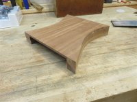
Firstly, though, some preparatory woodwork. I needed a switch and gauge panel in the kitchen area, whose other function is hide a whole lot of wires. I cobbled together some scrap sapele:

IMG_0433.jpg

IMG_0434.jpg

IMG_0435.jpgIMG_0436.jpg

IMG_0437.jpg

Just to make it's function clear, here's the rear view, which will hide a lot of stuff:
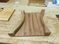
IMG_0438.jpg

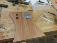
I made cut outs for the kitchen light switches and the battery monitoring gauge:
IMG_0439.jpg

And here it is temporarily in position (unfinished):

IMG_0441.jpg

Underneath all the drawers are a couple of compartments. One of them has always been intended as the site of the bulk of the electrics. So, I took the drawers out, made up a base board, and started wiring the principle components. The following photo contains an obvious wiring error, which most certainly wasn't the last:

IMG_0444.jpg

From top to bottom, that's a neutral take-off for the battery gauge (on the left) with a fuse on the positive circuit to the right. Below this is the negative buzz bar, then the fuse box, and finally the positive buzz bar. The cabling you can see is 16 sq mm stuff as it is bringing in full power from the battery. The two red cables heading up the wall behind go up to the isolating switch I showed a few photos back, which will isolate the battery from all loads. The red cable to the left of the fuse box is in the wrong place, and was soon attached to the buzz bar. Buzz bars can be though of as remote battery terminals, so all the main charging connections, and the main connection to the fuse board, happen from the buzz bars.

Looking further into the same compartment, you can see a 240V mains charger (blue) mounted on the board on the back wall of the compartment, plugged into a (RCD protected) socket on the left:

IMG_0445.jpg

You can also see a coil of data cable on the right, which leads to to the battery monitor gauge. This kit is designed for yachts, where presumably the gauge is further from the battery than it is here.

When the cabling and wiring is finished, the centre of the kitchen splashback should look something like this (with the addition of another isolating switch for the solar system):

IMG_0446.jpg

I drilled various holes to enables cables to be passed through from one area to another, and also to locate the (blue) water supply pipe. As always the plumber (me) and the electrician (me) on this job are fighting over the same small space. Here's the "before" of the battery & tank well:

IMG_0447.jpg

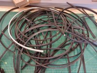
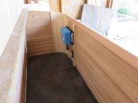
I didn't order quite enough 16 sq mm cable to finish the connection of the DC-DC charger:
IMG_0448.jpg

It sits inside the tongue box, raised off the surface, and eventually to have an air vent directly in front of it because it gets hot. It's function is to charge the leisure battery whilst we're driving.

What I don't seem to have a photo of is the solar controller, and the solar panel. Just as a fun aside, it took two days of emailing to get confirmation that cutting the terminals off the solar panel leads to fit them into the solar controller won't affect the warranty.

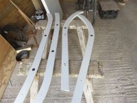
There follows a series of photos showing the chaos of the work in progress. There are wires everywhere. Firstly, though, some light switches in my wooden ducts/ conduit:
IMG_0451.jpg

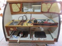
Then a general view of the back of the teardrop showing the electrical compartment at bottom left, and tools and components everywhere. Note the "cigar lighter" 12V sockets near the central partition (bottom, back) which will feed the fridge, the water pump, and the piezzo spark thingy for the gas hob:
IMG_0452.jpg

Some of you might remember the wine rack in the middle of the kitchen cupboards. I said at the time that its primary function was to hide some wiring. This is far from the final amount:

IMG_0454.jpg

IMG_0456.jpg

The last photo above shows the sink waste (black crinkly pipe in the back left hand corner). Squeezing that out through the bottom of the trailer was a task and a half.

Here's what the electric compartment look like at the moment. I've just about finished in there, I think, apart from the positive from the DC-DC charger to a buzz bar:

IMG_0455.jpg

Inside the bedroom of the teardrop, all the wires are just hooked over nails awaiting a final tidy-up, before covering with the wooden cover pieces:

IMG_0457.jpg

The only lighting in there will be from 2 overhead map lights on flexible stalks, individually switched from just above the headboard each side. There will also be switches for a "porch light" outside light above each door, and.......I think this is a good idea of mine..........a dim red light under the body of the teardrop just below the door. If you get up in the night you don't really want to be blinded by a floodlight, but being able to see to open the door and get in might be handy.

Here's the battery & tank well, featuring a cable tray on the far wall which will hold 8 or 10 cables, and a battery "holder" which will allow the battery to be moved forward or backwards to help with balancing the trailer correctly for towing. It also allows additional batteries to be added to increase the amount of time which can be spent without an electrical hook up:

IMG_0458.jpg

I'm awaiting the delivery of some more stuff, so that will probably be that for electrics for a day or two. I might have to have a look at the fibreglassing.......
 
Back
Top