• Hi all and welcome to TheWoodHaven2 brought into the 21st Century, kicking and screaming! We all have Alasdair to thank for the vast bulk of the heavy lifting to get us here, no more so than me because he's taken away a huge burden of responsibility from my shoulders and brought us to this new shiny home, with all your previous content (hopefully) still intact! Please peruse and feed back. There is still plenty to do, like changing the colour scheme, adding the banner graphic, tweaking the odd setting here and there so I have added a new thread in the 'Technical Issues, Bugs and Feature Requests' forum for you to add any issues you find, any missing settings or just anything you'd like to see added/removed from the feature set that Xenforo offers. We will get to everything over the coming weeks so please be patient, but add anything at all to the thread I mention above and we promise to get to them over the next few days/weeks/months. In the meantime, please enjoy!

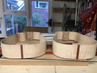
Two Concert Ukuleles (More or Less Finished)

Cabinetman":2dkl0v3m said:
Nicely positioned signature btw, lovely work, hope you have a good lunch and happy Birthday.
Can recommend the Tuckers Arms in Dalwood, bit far at 45mins but always superb, Ian


Thanks, Ian.

The Martlet at Langford Budville.

82FADB9C-41C5-4AC6-B20B-746C01E7BBAF_1_201_a.jpeg

It's Mission Control's birthday next month, so I sent her a link to The Tuckers Arms.
 
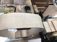
If you remember the wood mix of the rosette, black/white/padauk, I've got to inlay the back joins of the rims with the same sequence before I glue the tops and backs to their rims.

So I had a practice in an offcut of maple.

F68758B4-817F-403E-A5A5-82DE2C18B26C_1_201_a.jpeg

The first housing was too wide (by about 0.4mm!)

This is where the tail inlay will be going.

E5E63ADA-A3EA-4D11-9408-31BC09D1DEBA_1_201_a.jpeg
 
It didn't go too bad.

Fit the work in a vice. Mark the edges of the housing. Chisel down the marking line. Saw to depth then use a small router to cut out the housing.

9499C0AC-F1E9-4AB9-872F-6E11DF0EBFBD_1_201_a.jpeg

I'm becoming a real fan of CA glue. I dry fitted the three components into the groove, then wicked thin CA glue till it would wick no more. Then spritzed it with accelerator.

Then block planed off the top until I was just above the rim.

570DF57F-953E-4372-BA2D-2E604CB0910D_1_201_a.jpeg

Then used a cabinet scraper and sandpaper to finish off.

Rinse and repeat.

2D393CAA-DA90-4364-B39E-ED476D8DD701.jpeg

The second one, on the right, didn't come out as well as the first. This is the highly figured Sycamore. Small pieces of wood came away from the edge of the saw cut line. I made up some Sycamore dust, used a Stanley blade to cut it into the gaps (hope nobody saw me - looked like I was cutting a white powder into a line! :shock: ). Then drizzled CA glue onto the pile of powder, spritzed again then scraped back to main surface.

Ready for gluing the kerfed linings tomorrow.
 
While the instruments are still in pieces, this gives me the opportunity to think ahead and work out how to clamp the bridge in place when it is time glue it. It is one of the last operations before adjusting the saddle and nut on the instrument.

One way is to use long reach/deep throat clamps. (My evening class instructor used to call his deep throat clamp Linda. :) ) I have a couple for instruments guitar sized but not for ukuleles.

So I nicked/borrowed/acquired this idea from the pro on my course and internship.

The idea is to use the endpin/jack socket hole in the tail to offer a threaded rod through. Then place a shaped caul through the soundhole with a threaded insert for the rod to screw into and move the caul inside the instrument to under the bridge reinforcement.

The next part is to be able to screw a top caul via the string pin holes of the bridge through the body and into two threaded inserts on the internal caul. Thus tightening the the screws squeezes the top caul onto the bridge onto the body and the internal caul onto the reinforcement.

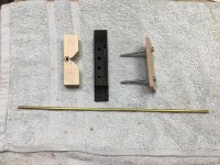
So here I go. I found a piece of brass rod in my stock and threaded it to M4. I made a caul and glued an M4 nut to receive the rod. If you remember the internal bracing, the top has a central brace, so I had shape a cut out to accommodate it.

B82AACAD-646D-408A-8FAD-ED239ABD71F3_1_201_a.jpeg

576BA57F-F0FB-4586-B261-4E2DD751FF15_1_201_a.jpeg

I then glued two M4 nuts into the top of the caul and ensured they were co-centric with the two outside string pin holes.

0D6F1011-D403-4853-8320-DED6608A4EB6.jpeg


I received a shipment of under saddle piezo pickups and endpin jack sockets today. So, I might have to either make the saddle slots deeper to accommodate the pickups, or make a new pair of bridges that will accommodate them.
 
Thanks, Ian. It's a mystery to me sometimes! :D

But you didn't spot my mistake.

The 'captive' nuts are on the workpiece side of the internal caul. If they should come adrift from the caul, and they could well do under torque twisting, then I'd be stuck with an M4 screw going through an external caul, the bridge, the instrument body with a nut on the other side and no way of undoing it.

So, I shall make another internal caul, with the nuts glued on its outer side. For belt and braces, I may cut off the screw head, and as I can't find any M4 wing nuts in my local Homebase, (5 x 50mm M4 screws and nuts - £5!! for goodness sake!) I shall use double nuts on the outside. If anything goes wrong, I can take those nuts off and the screw and caul can fall inside and be extracted from the sound hole.

It's not easy being me. ;)
 
9fingers":23iaxv7v said:
Malc2098":23iaxv7v said:
I can't find any M4 wing nuts in my local Homebase, (5 x 50mm M4 screws and nuts - £5!! for goodness sake!)
I regularly use ebay vendors for fixings in small quantities and modest prices. Usually arrive within a day or two.
The sheds are pretty hopeless and stupidly expensive.

eg
https://www.ebay.co.uk/itm/223769038199 ... BMppXPmrlh

These guys are very good https://www.ebay.co.uk/str/falconworkshopsupplies

Bob

Ditto. I often use kay fastener's on ebay for small quantities and if I'm buying a few more then their main website is a bit cheaper.
 
Dr.Al":29ia1rwk said:
9fingers":29ia1rwk said:
Malc2098":29ia1rwk said:
I can't find any M4 wing nuts in my local Homebase, (5 x 50mm M4 screws and nuts - £5!! for goodness sake!)
I regularly use ebay vendors for fixings in small quantities and modest prices. Usually arrive within a day or two.
The sheds are pretty hopeless and stupidly expensive.

eg
https://www.ebay.co.uk/itm/223769038199 ... BMppXPmrlh

These guys are very good https://www.ebay.co.uk/str/falconworkshopsupplies

Bob

Ditto. I often use kay fastener's on ebay for small quantities and if I'm buying a few more then their main website is a bit cheaper.

Agreed. Kays are very good too ( but I could not recall their name when I wrote my reply!)

Bob
 
When you chaps have quite finished hijacking my thread about roast potatoes you can't see………..

In order to secure the top and back to an instrument's rim, you need to glue it. But the rim's thickness is inadequate to provide sufficient gluing surface. So the usual method is to provide linings to the inside of the rims to increase the gluing surface.

There are two types; solid and kerfed. Solid linings need to be bent using either the bending iron or the side bending machine to the shape of the rim. Kerfed linings can either be home made or bought pre-kerfed to bend around the rim allowing the gaps to close up or open out depending one whether it's an outside or inside curve.

For my instruments, I'm using bought kerfed linings, and guess how you clamp them to the rim.

00528EE0-ADE8-47F1-8369-C8FEE8EE0402_1_201_a.jpeg

There's no washing out today, even in this sunshine. ;)


1556484E-5F2C-42D3-BDD7-10BD4018FA17_1_201_a.jpeg

Rinse and repeat for the other side, then twice more for the other instrument.
 
I've never used the bought ones. Never occurred to me - but I am long out of the game. Just made my own because I cold use variable slot spacing depending on the curvature. I always wondered if the slots affected the sound waves in the sound box. Have never seen solid ones with no slots. (I don't follow luthiery sites at all). Clothes pegs are traditional and work fine. I glued little leather pads to mine as on sides like maple they mark easily until the finish is applied.

Really nice to see a detailed WIP like this. :text-bravo:
 
Thank you, Adrian.

You may remember that I machined formers on the CNC and also a dished sanding disc. Today, they've both been in action. Well, I have, actually. they just sat there.

Sanding the kerfed linings back down the rim contour using the 1200mm radius sanding dish. (And the flat side for sanding the top flat.)

4CC7EDD6-343B-49B2-BF1B-42439DD85579.jpeg

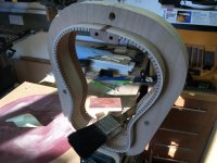
The former holds the rims nicely in the vice to tidy up the insides. Probably nobody will ever see this, but if a job's worth doing….

I wrap a piece of self adhesive abrasive around a bit of plastic tube.

8EB9770C-99F4-4479-93C3-503EEDECCC4B.jpeg

The former lets the vice hold it at any angle.

076744F4-F9AB-4972-96BE-CE5F40B9C2E4.jpeg

And while this is going on, the cutaway model is having its kerfed linings glued in place. Bloomin' cold in there today!
 
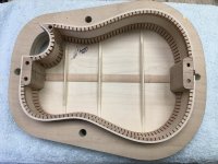
All the lining of both instruments have now been glued but left proud of the rims, so they now have to be sanded down. Out with the sanding disc again and the first back is sanded to the rim contour and the back braces are housed into the linings.

C13AF646-8F27-4C20-B85E-121CEBEAD61C.jpeg

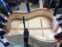
Showing the back, laterally curved by the braces, can now be longitudinally curved over the rim contour. The clamps are so I can have my hands free to take the photo. But I can assure you there are no gaps between the rim and the back because the sanding disc contoured the rim to the same disc radius as the braces were contoured.

D6CF66FB-07B4-488F-856D-FA7D4C2E8F8C.jpeg

Rinse and repeat with the cutaway model.

124A6B19-F22B-41D5-89A2-9131A10DC507_1_201_a.jpeg

And house the brace ends.

E8470458-8B1B-44C1-9B9F-3EA89E550005_1_201_a.jpeg

That's both backs done.

91CA7193-B611-4E0C-BD5C-5FC24500A871_1_201_a.jpeg

Now to do the same for the tops.

1BC18536-6AC1-48C7-AAF3-193E8AC0B123_1_201_a.jpeg

And the other one.

0AF2550D-9C9E-4A5D-80A2-159711D90A55_1_201_a.jpeg

That's both now ready to 'close the box'………

C6269D59-D0EC-499D-8649-C448C171A3DB_1_201_a.jpeg

…….I think. :eusa-think:
 
I know you've signed them, but I would start numbering your instruments and glue a nice label label on the inner back immediately beneath the sound hole. This could be a wooden carved label since you have CNC.

When you get little pieces chipping off the kerfing (as was the case once or twice here going by the photos) do you repair them before glueing the back or top on?
 
These two are 6 and 7, and they will have a small paper label. I will look into CNC timber labels in the future.

Where little pieces of of the kerfed lining chipped off, and that only happened on one of these, I completely removed the chipped wedge and glued in place a full wedge and then sanded back when dry to the rest of the contour.

What could be mistaken for chipping off the kerfed linings in the photos are the housings that I have cut for the top and back braces.
 
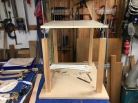
To use the go-bar deck to clamp the tops and backs to the rims, I'll have to raise its roof.

Extend the pillars.

D32497E9-2E8A-4E04-B523-E9033BEC661E.jpeg

And replace the roof.

255EB52B-A6AE-4F13-A4DF-B34B458F5E0F.jpeg

As the next gluing process is the most critical, and is with Titebond Original, I shall wait until I can warm the workshop up to above 9 degrees.

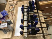
In the meantime, I've replaced one led panel, and started gluing veneers together to make binding and purfling a one process job.

04A347BC-6968-437F-96BF-37D973AE10B3_1_201_a.jpeg
 
This is all looking really good Malcolm.

As I think I’ve said before I have virtually no interest in musical instruments (playing or making) but I’ve really enjoyed your well put together thread so thank you for taking the time and effort to do it.
 
Stuart":1t4to9yj said:
This is all looking really good Malcolm.

As I think I’ve said before I have virtually no interest in musical instruments (playing or making) but I’ve really enjoyed your well put together thread so thank you for taking the time and effort to do it.

I can here the echos all over The Woodhaven from here. :eusa-clap:
 
I’m mystified by the go deck clamping scheme. Even with normal clamps the slightest bit of out of square pressure from the clamps causes the parts to slide

These go bars must give even more side thrust. Doesn’t everything slip?
Bob
 
9fingers":1k4xl9gr said:
I’m mystified by the go deck clamping scheme. Even with normal clamps the slightest bit of out of square pressure from the clamps causes the parts to slide

These go bars must give even more side thrust. Doesn’t everything slip?
Bob

I'll put the kettle on, Bob. Pop round and I'll give you a demo. ;)

If you remember years ago, I posted an image of me showing the bent rods' effort on kitchen scales.

IMG_3828.JPG

That demonstrates their downward force. There is sandpaper stuck on the underside of the roof, so where I place the tip of the rod should not slip.

I have used cork cauls on the workpiece before and the cork 'gives' a little so they don't normally slip. The trick is to keep the tip on the top of the rod to be immediately above the tip on the workpiece.

But some of the workpieces, like the soundboard braces are so tiny, about 3 to 5mm wide, that it's more accurate to place the rod tip on the brace, rather than cover it up with cork. The times that they have 'pinged' off, and when they go they fly off in any direction, have been when I haven't got the top tip right above the bottom tip and the brace has rolled over with that sideways force.

And I've never had the braces slide. they shouldn't if the force is directly downwards.

What else can I tell you? it works for me and loads of other makers.
 
Thanks for the explanation but the slip I experience and wonder about is between the items being glued. I don’t doubt they work but wonder how/why. even with a slightly skewed f clamp say the joint will slide on the film of glue.

Bob
 
9fingers":2fl3tc93 said:
Thanks for the explanation but the slip I experience and wonder about is between the items being glued. I don’t doubt they work but wonder how/why. even with a slightly skewed f clamp say the joint will slide on the film of glue.

Bob


I'm not an engineer, but it sounds like your workpiece is taking the line of least resistance, and so is it the skew that is reducing the resistance?

If I've got the top tip directly over the bottom tip, the force is directly downwards even if the rod is curved/bent. Why should it slip sideways?

I started with squared stock for the braces and only carved the angular shapes after they'd been glued. So all the resisting forces were up facing the downward forces.

Blimey this is getting heavy! :)
 
I managed to get the glue to cure eventually on this white/black/padauk veneer binding/purfling mix.

I glued four strips of padauk over an already glued wide trip of black and white dyed lime veneer, and then split them with a stanley blade before shooting one edge.

2FF73A3A-29DC-4C36-AB6F-CDD9DA19463B_1_201_a.jpeg

It's not this edge that will be seen. This shot edge will fit in the routed rebate squarely and the rough side will be squared up with the rim/top of rim/back.

The polyurethane glue should allow me to heat bend the laminate strips around the heating iron to fit the shapes of the instruments.
 
Just to get Bob 9F wondering again….. :)

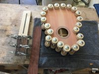
First instrument's rim being glued to its soundboard.

B610133A-5541-46A8-A8D1-58CC730C641E.jpeg

The towel is to provide a little 'give' for the soundboard to soak up any minor undulations.

28C3C26F-6772-484C-B96F-EFAE3C151E73.jpeg

I hope this image can show the tops of the rods are as close as I can get them to be above the bottoms of the rods, as well as the sandpaper to stop the tops slipping. In fact, I place the top first so it won't move, place the bottom next, then adjust the top if necessary to be directly over the bottom of the rod.

Strictly speaking, if I get it right, the placements of the tops should be exactly the same as on the workpiece. But I'm not going to photo that for you. ;)

Oh, and the outer former stays on so that the pressure of the rods doesn't splay the rim's shape at all and maintains the rim 90 degrees to the deck/soundboard.
 
Cabinetman":25z5bwms said:
Fascinating, I suppose if you didn’t have that kit you could just go round the edge with G cramps, which is probably what they did in the old days.

Thank you.

In the olden days, I still think the deck would have been used but with wooden rods.

But, I think G clamps would be too heavy. Spool clamps would have been used and still are.

s-l500.jpg

Not these, but I made my own from stud, plastic discs and wing nuts for the first instrument I made, and on the course earlier this year, I used spool clamps for the Tenor Ukulele I made, because his deck was being used for something else.

I prefer the deck. I think I can get more control on what is quite a fragile workpiece.
 
Cabinetman":1u3suce4 said:
Fascinating, I suppose if you didn’t have that kit you could just go round the edge with G cramps, which is probably what they did in the old days.

What I used on the my Tenor Ukulele course last year.

89010774-3392-4AAF-A206-91B02BC6866F.jpeg
 
Seems to me the sprung rods method is far quicker and will give very even downward pressure. Cheap too.
 
AJB Temple":1ny07dbv said:
Seems to me the sprung rods method is far quicker and will give very even downward pressure. Cheap too.


What were used on your violin making course, Adrian?
 
Phil":2e3kyh80 said:
Malc2098":2e3kyh80 said:
Just to get Bob 9F wondering again….. :)

Nice Malc.

Can you do a video showing how you do it? :D

Anything to oblige, Phil. ;) (Video at 4 x playback speed.)

[youtubessl]dWfo54f0-Ik[/youtubessl]
https://youtu.be/dWfo54f0-Ik

This instrument had already been glued, so this is just a demo. But in any case, the rim could not slip on the soundboard, Bob, because I had housed the ends of the transverse braces into the kerfed linings.

As a mater of interest, you might notice the contour of the rim above the former showing the shape the back will take on when it's glued to the rim.
 
Back
Top