-
Hi all and welcome to TheWoodHaven2 brought into the 21st Century, kicking and screaming! We all have Alasdair to thank for the vast bulk of the heavy lifting to get us here, no more so than me because he's taken away a huge burden of responsibility from my shoulders and brought us to this new shiny home, with all your previous content (hopefully) still intact! Please peruse and feed back. There is still plenty to do, like changing the colour scheme, adding the banner graphic, tweaking the odd setting here and there so I have added a new thread in the 'Technical Issues, Bugs and Feature Requests' forum for you to add any issues you find, any missing settings or just anything you'd like to see added/removed from the feature set that Xenforo offers. We will get to everything over the coming weeks so please be patient, but add anything at all to the thread I mention above and we promise to get to them over the next few days/weeks/months. In the meantime, please enjoy!
You are using an out of date browser. It may not display this or other websites correctly.
You should upgrade or use an alternative browser.
You should upgrade or use an alternative browser.
Dr Al's Latest Folly
- Thread starter Dr.Al
- Start date
Dr.Al
Old Oak
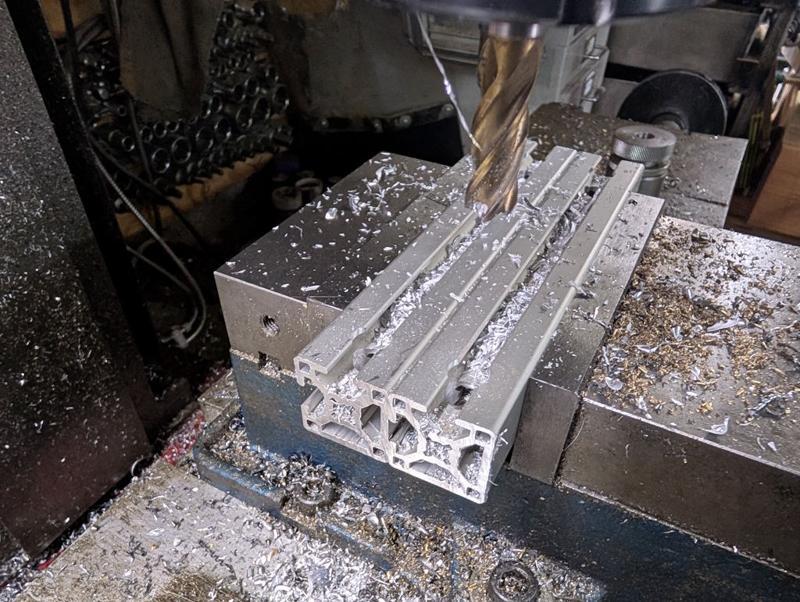
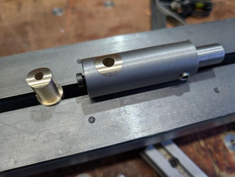
A minor machining job was done today. As the spindle is a little longer than the old one, I needed to replace the two pieces of aluminium extrusion that connects the lathe to the motor assembly. That was a fairly simple job, just a case of milling two bits of extrusion to the same length and then drilling (with an end mill) an 11 mm hole near each end for the clamping thing:
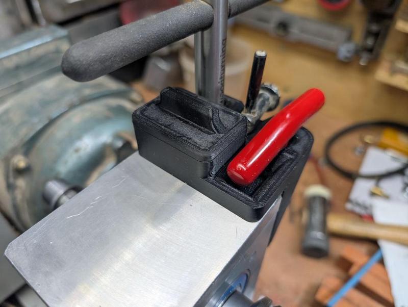
Most of the rest of what I've been doing today has been fitting 3D printed bits and bobs that have been made over the last week. The first one is a new chuck key holder. The old one was held in place with magnets and would occasionally come loose when removing the chuck key. The new one is screwed to the headstock. It holds the key for my lathe chucks, the key for the Jacobs drill chuck and a 4 mm T-handle Allen key which deals with most of the screws on the lathe (including the ones for the lathe chucks):
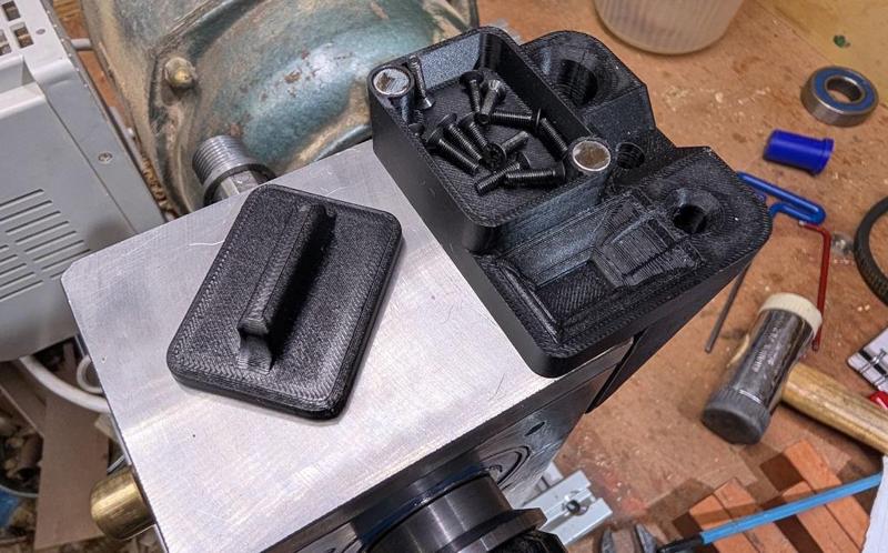
It also has a little pot for temporarily holding screws (e.g. the chuck screws when swapping jaws). The old one had this as an open top pot but, of course, it tended to fill up with sawdust so the new one has a magnetically-attached lid:
I also decided to replace the laser cut acrylic dividing wheel number discs with a single 3D-printed one. Here it is on the print bed:
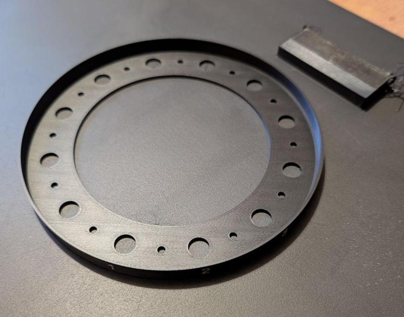
That gets held in place with M3×10 mm countersunk screws and wraps around the outside of the disc, giving numbers that I think will be easier to see:
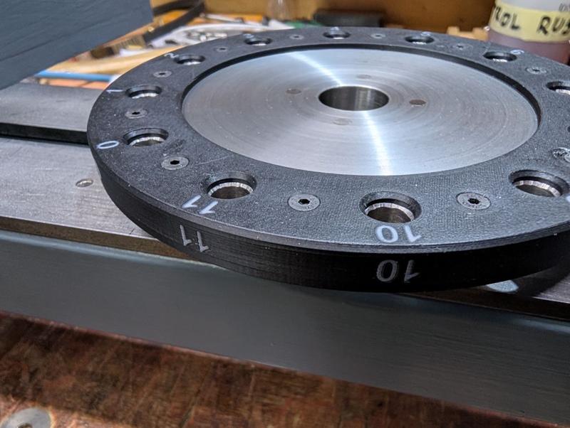
Here it is fitted to the spindle:
Those of you who have been following from the start might remember the belt guard I made when I first made the lathe. You can see it on the left of this old photo:
That belt guard obviously guarded the belt (and the motor, and the drive) and was very effective at keeping sawdust out the way, but it also got in the way a lot. In particular, it prevented me from putting a bar in the rear of the spindle to eject the drive centre. As a result, it didn't last long and ended up being cut up into bits and returned to the sheet metal drawer.
I went through quite a few designs in CAD for a new belt shield. The first one (second if you count the original guard) was similar to the original just a heck of a lot smaller. The second one tried to add a bit more curvature to the front surface and allow it to hinge. Finally, I realised that (in design number 3) I could just 3D-print it rather than restricting myself to shapes I could easily form from sheet metal. That gave me a lot more design freedom.
Of all the things I've ever printed, this is perhaps the least-suited to 3D-printing. Hardly any of it is actually on the bed of the printer (most of the lower surface sits on a support structure) and there's loads of supports internally:
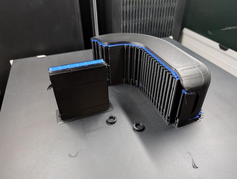
The two little ring things are caps to cover some magnets that get glued into the belt guard.
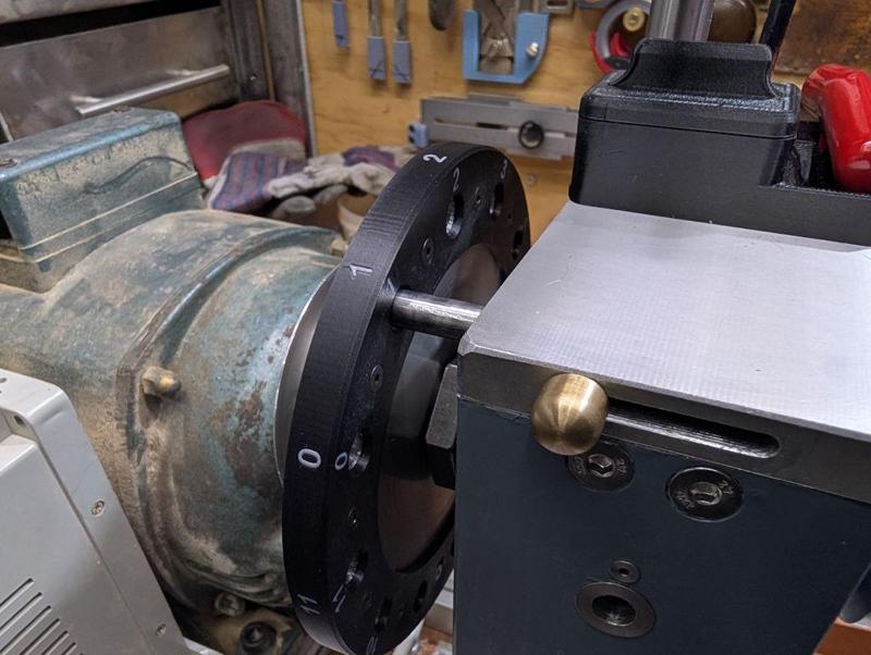
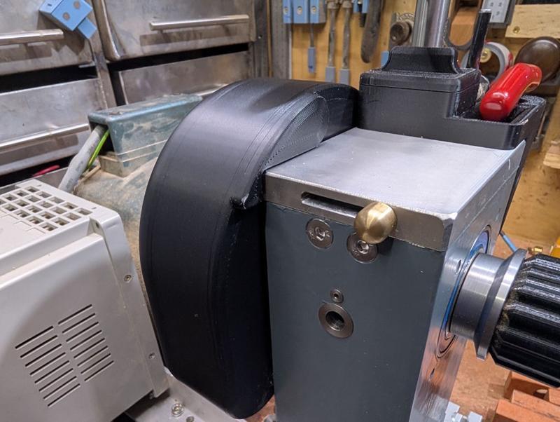
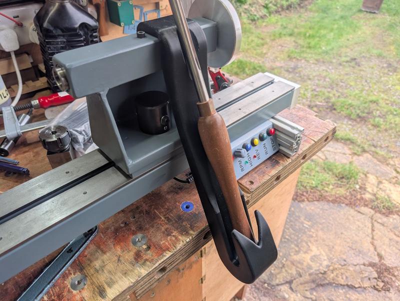
This is what it looks like mounted on the lathe. It covers the dividing wheel and the pulley but, as you can see in the following photo, still allows access to the rear of the spindle if required:
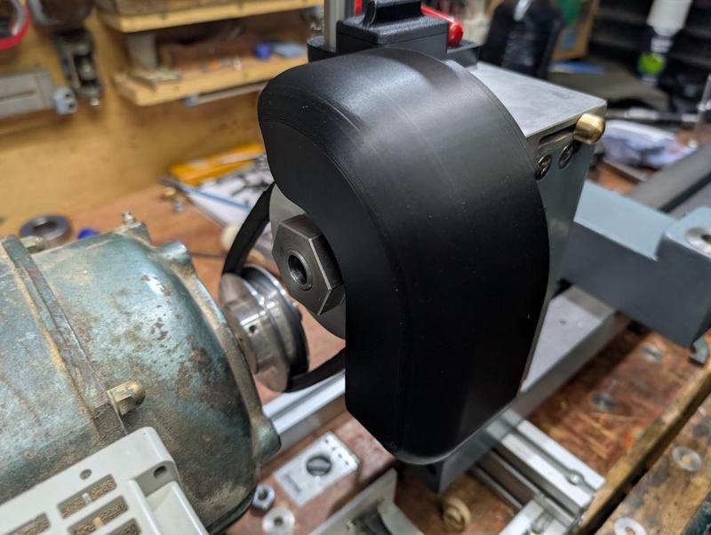
It's held in place rigidly with a single M5 cap screw that attaches to the lid of the headstock. Access to that screw is through one of the holes in the dividing wheel. There are also two 8 × 6 mm magnets that hold it to the headstock at the front to stop it rattling around.
It has the added benefit of covering up the end of the dividing head locking pin, so there's no chance of the locking pin sliding out while the lathe is running.
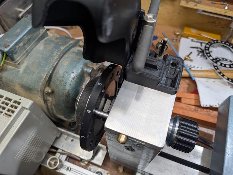
With the cap screw at the back loosened, it can be tilted up and stops (by hitting the chuck key holder) at this angle, allowing access for dividing (or fitting the belt when setting up the lathe):
Another quick 3D-print was this (magnetically attached) cover for the slot for the dividing pin, which will hopefully keep the sawdust out:
As you can see, I still haven't made the cover for the tommy bar hole (and there's a bit of stray plastic on that cover that I only noticed when I saw the photo - since removed).
You may remember that I made a "Lazy Susan" for my wood lathe tools:
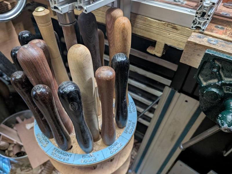
When I'm turning, I tend to find that I often want to put a tool down for a few seconds just to (say) measure something. I tend to do that by plonking it on the bench (as it's quicker than spinning the Lazy Susan and dropping it into its home), which is a bit awkward (especially as I often end up with a lot of clutter on the bench that I'd rather keep away from the tool tip).
As an alternative, I 3D-printed a temporary tool holder, with six 8 × 3 mm magnets glued into it to hold it in place on the tailstock (this was right up at the limit of what I could fit on the bed of my printer):
The bottom end of that tool holder has a hole in it, which will hopefully allow sawdust to drop out the bottom.
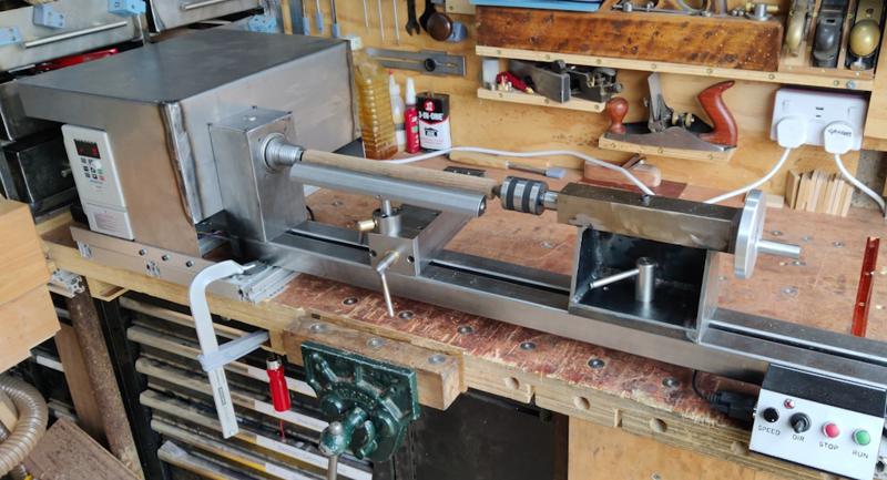
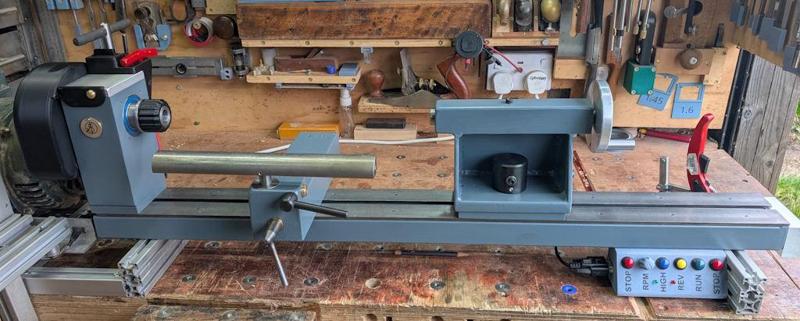
Apart from the tommy bar hole cover, that's everything done on the lathe, so I thought I'd have a bit of a tidy up and take a couple of photos:
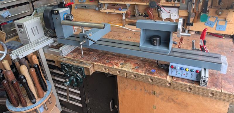
I'm really pleased with how the lathe is looking (it's still in that nice phase before any of the paint has chipped off!) and it does feel like the work I've done over the last few weeks has been a worthwhile improvement.
Hopefully I'll get that tommy bar hole cover finished next weekend and then I can really call it done.
Most of the rest of what I've been doing today has been fitting 3D printed bits and bobs that have been made over the last week. The first one is a new chuck key holder. The old one was held in place with magnets and would occasionally come loose when removing the chuck key. The new one is screwed to the headstock. It holds the key for my lathe chucks, the key for the Jacobs drill chuck and a 4 mm T-handle Allen key which deals with most of the screws on the lathe (including the ones for the lathe chucks):
It also has a little pot for temporarily holding screws (e.g. the chuck screws when swapping jaws). The old one had this as an open top pot but, of course, it tended to fill up with sawdust so the new one has a magnetically-attached lid:
I also decided to replace the laser cut acrylic dividing wheel number discs with a single 3D-printed one. Here it is on the print bed:
That gets held in place with M3×10 mm countersunk screws and wraps around the outside of the disc, giving numbers that I think will be easier to see:
Here it is fitted to the spindle:
Those of you who have been following from the start might remember the belt guard I made when I first made the lathe. You can see it on the left of this old photo:
That belt guard obviously guarded the belt (and the motor, and the drive) and was very effective at keeping sawdust out the way, but it also got in the way a lot. In particular, it prevented me from putting a bar in the rear of the spindle to eject the drive centre. As a result, it didn't last long and ended up being cut up into bits and returned to the sheet metal drawer.
I went through quite a few designs in CAD for a new belt shield. The first one (second if you count the original guard) was similar to the original just a heck of a lot smaller. The second one tried to add a bit more curvature to the front surface and allow it to hinge. Finally, I realised that (in design number 3) I could just 3D-print it rather than restricting myself to shapes I could easily form from sheet metal. That gave me a lot more design freedom.
Of all the things I've ever printed, this is perhaps the least-suited to 3D-printing. Hardly any of it is actually on the bed of the printer (most of the lower surface sits on a support structure) and there's loads of supports internally:
The two little ring things are caps to cover some magnets that get glued into the belt guard.
This is what it looks like mounted on the lathe. It covers the dividing wheel and the pulley but, as you can see in the following photo, still allows access to the rear of the spindle if required:
It's held in place rigidly with a single M5 cap screw that attaches to the lid of the headstock. Access to that screw is through one of the holes in the dividing wheel. There are also two 8 × 6 mm magnets that hold it to the headstock at the front to stop it rattling around.
It has the added benefit of covering up the end of the dividing head locking pin, so there's no chance of the locking pin sliding out while the lathe is running.
With the cap screw at the back loosened, it can be tilted up and stops (by hitting the chuck key holder) at this angle, allowing access for dividing (or fitting the belt when setting up the lathe):
Another quick 3D-print was this (magnetically attached) cover for the slot for the dividing pin, which will hopefully keep the sawdust out:
As you can see, I still haven't made the cover for the tommy bar hole (and there's a bit of stray plastic on that cover that I only noticed when I saw the photo - since removed).
You may remember that I made a "Lazy Susan" for my wood lathe tools:
When I'm turning, I tend to find that I often want to put a tool down for a few seconds just to (say) measure something. I tend to do that by plonking it on the bench (as it's quicker than spinning the Lazy Susan and dropping it into its home), which is a bit awkward (especially as I often end up with a lot of clutter on the bench that I'd rather keep away from the tool tip).
As an alternative, I 3D-printed a temporary tool holder, with six 8 × 3 mm magnets glued into it to hold it in place on the tailstock (this was right up at the limit of what I could fit on the bed of my printer):
The bottom end of that tool holder has a hole in it, which will hopefully allow sawdust to drop out the bottom.
Apart from the tommy bar hole cover, that's everything done on the lathe, so I thought I'd have a bit of a tidy up and take a couple of photos:
I'm really pleased with how the lathe is looking (it's still in that nice phase before any of the paint has chipped off!) and it does feel like the work I've done over the last few weeks has been a worthwhile improvement.
Hopefully I'll get that tommy bar hole cover finished next weekend and then I can really call it done.
Dr.Al
Old Oak
This afternoon I thought I'd have a go at the table for the sanding disc. I started with the big bit of 10 mm thick aluminium plate that I found in a skip and marked a seemingly appropriately sized section out with a pencil then used a jigsaw to cut it out:
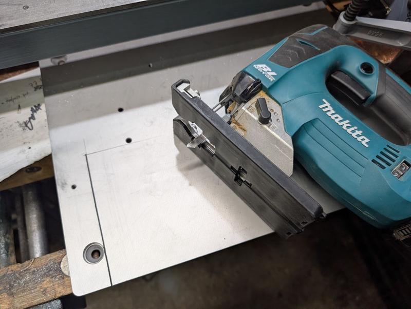
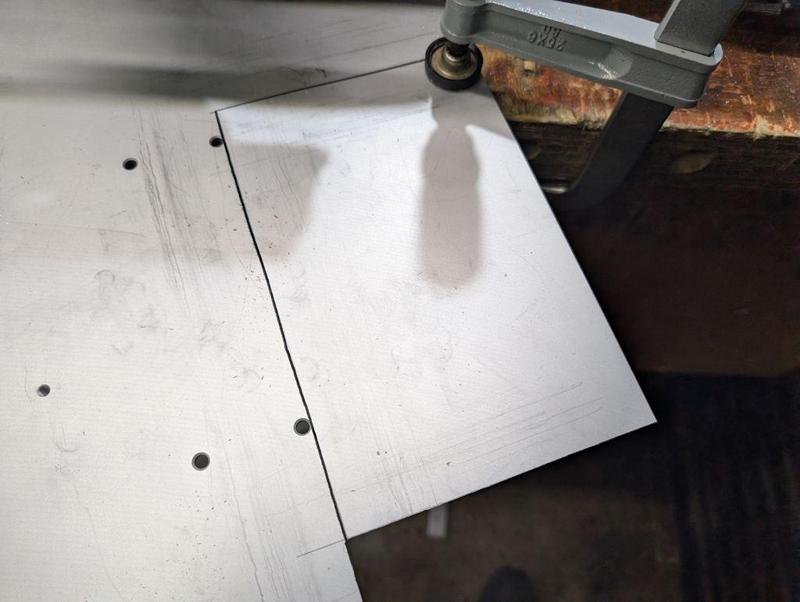
That's the thickest metal I've ever tried to cut with a jigsaw (the depth of cut on my metal-cutting bandsaw wouldn't have been sufficient). It and the (Makita B-23) blade seemed to make fairly light work of it so I was quite impressed. It was fairly slow, but it was steady and the blade was cool at the end of the cut. The last cut was done with the plate held to the bench at an angle to make sure both the table and the off-cut were supported:
I probably could have left it with the jigsaw-cut edges, but I decided to clean them up with the mill. The long edge was straightforward:
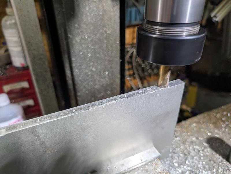
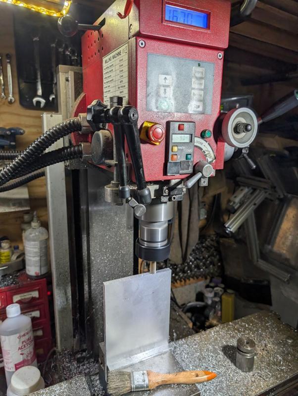
For the short edge, I'd usually do that sort of thing with the part held horizontally and the side of an end mill travelling across the part. However, this part is too wide for the "Y" axis travel of my milling machine so I did it with the part standing upright. There was just enough clearance (although I could have used a shorter type of tool holder):
A very simple base was turned from a bit of 35 mm EN1A. It's got a short section reduced to 16 mm (to match the tool post diameter) and three M6 holes tapped in the opposite end:
Three matching countersunk holes were drilled in the table and the two bits could then be screwed together and fitted:
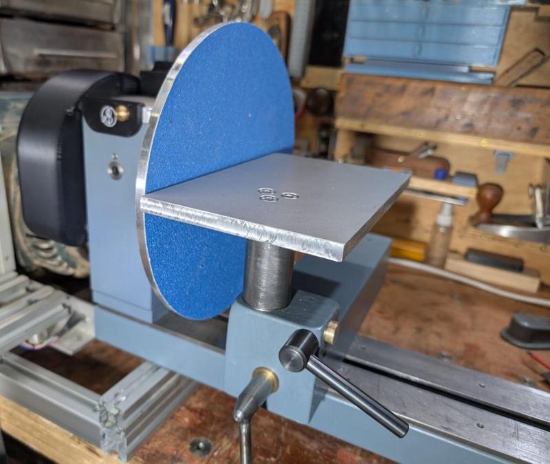
At the moment, I've got it set so that when the post is resting on the top of the banjo the top of the table is at centre height. It looks a bit high to me and, having now looked at a few commercial disc sanders, they seem to be set a bit below centre height.
It'll be a simple enough job to extend the 16 mm section of the base shaft (and hence lower the table) once I've decided how far to go.
That's the thickest metal I've ever tried to cut with a jigsaw (the depth of cut on my metal-cutting bandsaw wouldn't have been sufficient). It and the (Makita B-23) blade seemed to make fairly light work of it so I was quite impressed. It was fairly slow, but it was steady and the blade was cool at the end of the cut. The last cut was done with the plate held to the bench at an angle to make sure both the table and the off-cut were supported:
I probably could have left it with the jigsaw-cut edges, but I decided to clean them up with the mill. The long edge was straightforward:
For the short edge, I'd usually do that sort of thing with the part held horizontally and the side of an end mill travelling across the part. However, this part is too wide for the "Y" axis travel of my milling machine so I did it with the part standing upright. There was just enough clearance (although I could have used a shorter type of tool holder):
A very simple base was turned from a bit of 35 mm EN1A. It's got a short section reduced to 16 mm (to match the tool post diameter) and three M6 holes tapped in the opposite end:
Three matching countersunk holes were drilled in the table and the two bits could then be screwed together and fitted:
At the moment, I've got it set so that when the post is resting on the top of the banjo the top of the table is at centre height. It looks a bit high to me and, having now looked at a few commercial disc sanders, they seem to be set a bit below centre height.
It'll be a simple enough job to extend the 16 mm section of the base shaft (and hence lower the table) once I've decided how far to go.
Cabinetman
Sequoia
- Joined
- Oct 11, 2020
- Messages
- 5,225
- Reaction score
- 994
- Location
- Lincolnshire Wolds + Massachusetts
- Name
- Ian
Looks very smart Al, personally I think just below centre, 10mm below?
Dr.Al
Old Oak
Thanks Ian, that's useful. On the pictures I've seen of them they seem to be just below centre but I hadn't figured out what "just" meant yet! It's easy enough to tweak (especially lowering it), so I'll probably drop it by 10 mm and then see what it looks like. If it needs to go further then so be it.Looks very smart Al, personally I think just below centre, 10mm below?
Alasdair
Sapling
When I was an apprentice, we were building toilets at a local engineering shop for the workforce. You know the type of thing typical 80's basic concrete block walls, 4x2 standards and flush ply door with only 3" pencil round facing and no skirtings (doors 6" off the ground so the foreman could see if anyone was hiding). I was fitting the basic facings while Big Robert my journeyman was observing my progress with a ciggie and mug of something resembling tea, one of the engineers came strolling past in his blue (and oil black) lab coat stopped for a smoke and observed my progress "you know as an engineer we work to tolerances of 1/1000th of an inch” he more or less boasted, without missing a beat Big Robert replied “you’re lucky we don’t get tolerances we need to get these joints tight everytime”. There then followed a heated discussion between the two about their respective trades (both in very broad West of Scotland accents) where I learned some new phrases and swear words.Fascinating read and work.
Metal work has to be much more accurate than woodwork.
Well done.
Alasdair
Sapling
This is a fascinating and highly enjoyable read (as others have said). The world of precision engineering is an alien one to me but it is nonetheless extremelly interesting.
Dr.Al
Old Oak
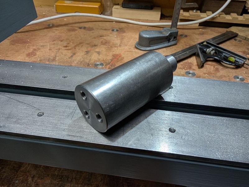
I made another simple upgrade to the lathe today. Here it is along with an alternative brass bush:
It fits into the tool post with the base resting on the banjo and, assuming I've got my maths right, the hole in the brass insert should be exactly on centre height. It can then be used to guide a drill bit into a work-piece. I've made two of the brass bushes, one with a 6 mm hole and one with an 8 mm hole. Those two sizes can be used with 6 mm and 8 mm drill bits but also with all of my Forstner bits up to 22 mm diameter.
There's a line scribed in the top parallel with the cross hole which can be used to help line things up. This is what it looks like in-situ with a 16 mm Forstner bit fitted:
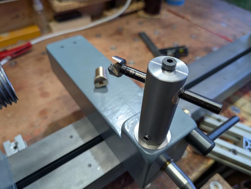
This will be used in combination with the new dividing wheel if I ever feel the urge to make something like a mug tree.
It fits into the tool post with the base resting on the banjo and, assuming I've got my maths right, the hole in the brass insert should be exactly on centre height. It can then be used to guide a drill bit into a work-piece. I've made two of the brass bushes, one with a 6 mm hole and one with an 8 mm hole. Those two sizes can be used with 6 mm and 8 mm drill bits but also with all of my Forstner bits up to 22 mm diameter.
There's a line scribed in the top parallel with the cross hole which can be used to help line things up. This is what it looks like in-situ with a 16 mm Forstner bit fitted:
This will be used in combination with the new dividing wheel if I ever feel the urge to make something like a mug tree.
Dr.Al
Old Oak
Hmmm, I'm not sure that's true really. If I were going to make a clock (which I doubt will ever happen), I think it would be brass and made on the metal lathe and the milling machine. We have a mug tree in the kitchen and, while it's handy for holding the mugs, it's pretty grotty wood so I can imagine myself deciding to make a replacement at some point.Mug tree? I reckon some gears for a wooden clock would be more in your line...
Dr.Al
Old Oak
I've mentioned a couple of times that one of the remaining jobs on the lathe was to make the little cover flap that goes over the tommy bar access hole in the front of the headstock. You may also have wondered why I didn't just get on with it and get this ostensibly simple part made.
The truth is that I wanted to use it as an opportunity to try something new and it's taken me until today to figure the process out (having started on the 2nd January). If/when I do it again I'll make some minor tweaks but essentially I think it's repeatable finally.
I think the one I've finished today would probably be the fourth complete attempt, but some of the earlier stages were definitely tried out a lot more times than that. Note that the photos below aren't all from the same disc so don't be surprised if things look a bit different from one to the next!
I started with a fairly simple process of taking some 31.75 mm (1¼") brass bar and skimming the outside down to a nice round 30 mm. I then went through a sequence of facing, parting, facing, parting:
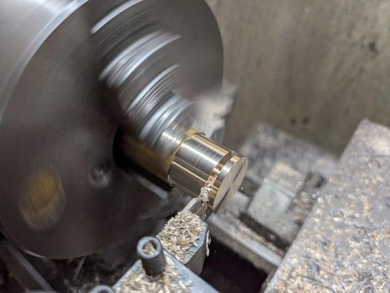
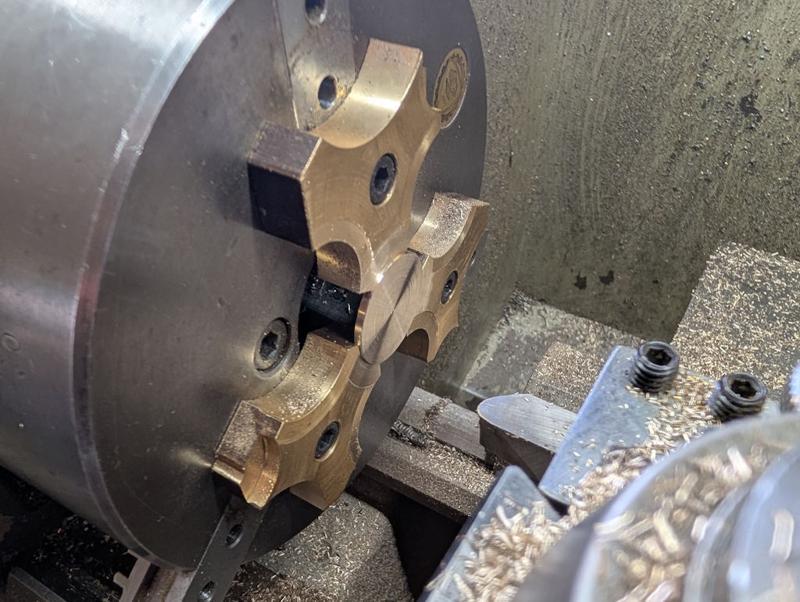
That photo was from the first attempt; on later ones I reduced the thickness of the parted off bit. The parted off bits got put back in the lathe using my home-made soft-jaws and each one had its parted face cleaned up with a round-nose tool:
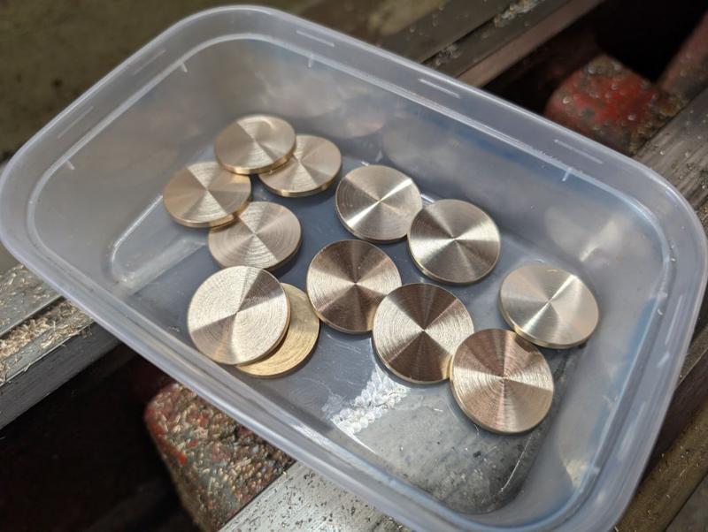
That left me with quite a few discs to play with; this was the set I made for the final round of testing:
The finish I need for the "show" face needs to be smoother than I can get off the lathe. To help with holding the thin parts, I 3D-printed a little holder with a shallow rim:
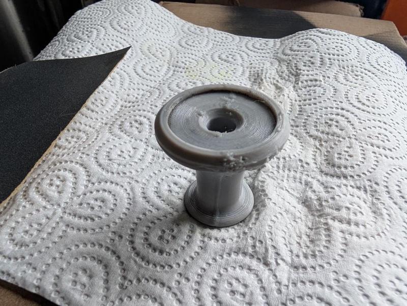
That didn't print that well (it was with a reel of filament that had been lying out on the table and probably needed to be dried) but it's good enough. With the discs in the recess in the top face as shown in that image, I flipped them both over and rubbed the disc face on wet-and-dry paper under running water (to make sure no brass swarf accumulates and scratches the surface):
I started at 240 grit (on a 12 mm thick sheet of glass) and followed that with 400 grit and 600 grit. If I do it again I might go up to 1200 grit.
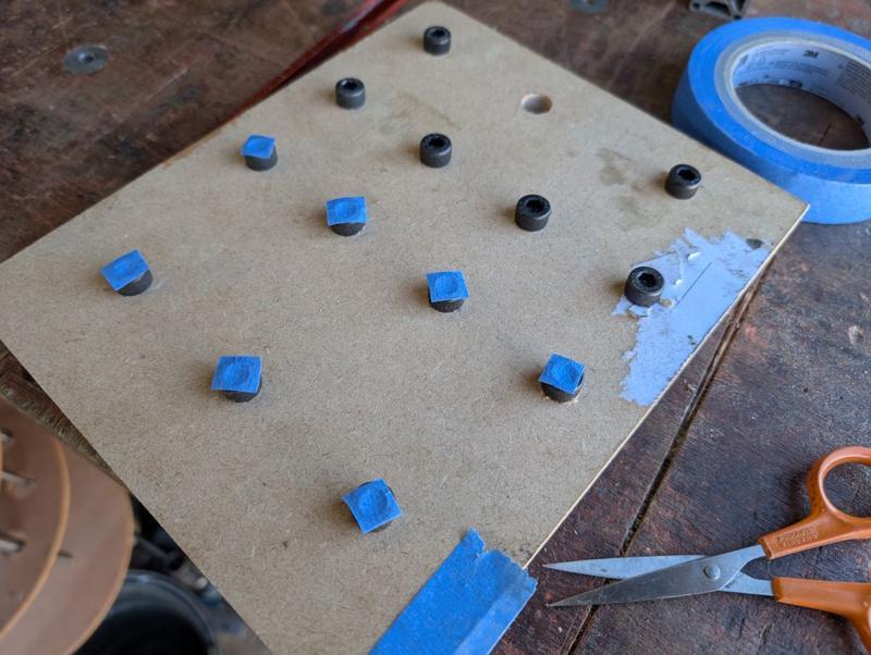
I had a scrappy bit of MDF with some blind holes on one side. I drilled them through about 7.5 mm and tapped them M8 before inserting some short cap screws and covering the caps with masking tape. If I do this again, I'll probably ditch the masking tape:
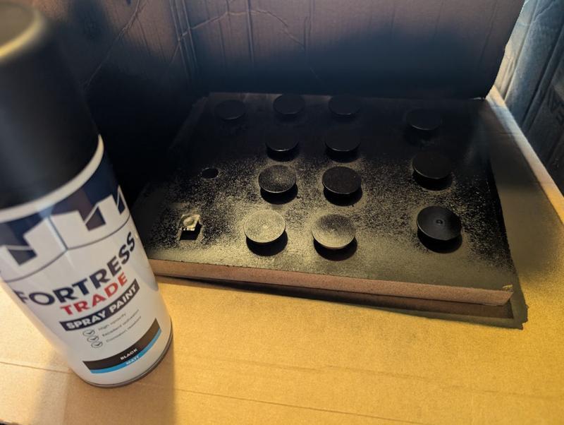
The discs got placed (sanded face down for the first coat) on the MDF, which was placed on a cardboard base (in the dining room for warmth reasons) and surrounded on three sides with more cardboard. The discs then got four coats (15 minutes apart) of Screwfix black spray paint:
After allowing about 8 hours for the paint to dry, I flipped them over and gave the sanded faces four coats. I later noticed that the masking tape had left a slight residue on the sanded face. It wasn't a big deal in the end, but I think if I do it again I'll paint the show face first and then (carefully) place that on the screw heads (possibly after skimming the screw heads on the lathe to minimise the chance of scratches in the paint).
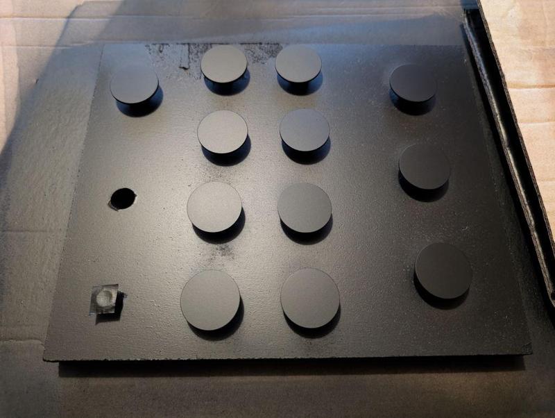
Here are a batch of 12 discs after the paint had dried:
I'd also painted a bit of brass sheet and I used that to calibrate the laser attachment on my 3D-printer:
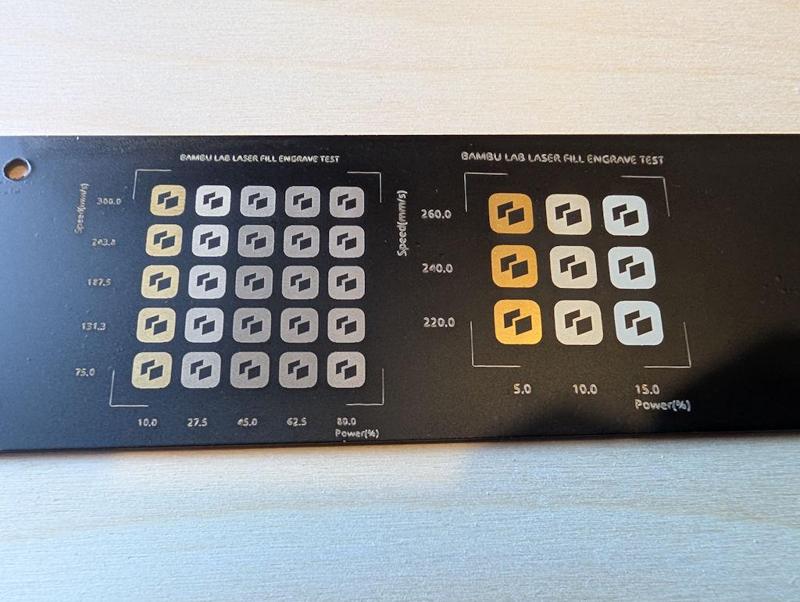
I did find the laser calibration settings depended (unsurprisingly) on the number of coats of paint, as well as on the thickness of each layer. The conclusion I came to was that increasing the number of passes (i.e. the number of times the laser engraves the image) was a good thing. More passes increases the likelihood of getting rid of all the paint but allows the power to be kept low so that there's less chance of removing paint in the wrong places.
I've found the accuracy of the camera used for alignment of the printer's laser is pretty awful, so I needed a way to deal with that. I started by cutting some 30 mm discs out of 3 mm thick plywood using the laser. I then fitted a sheet of 4 mm plywood and ran the laser job with the pattern I wanted as a laser fill (i.e. engrave) and the outline as a laser cut. That gave me some 30 mm pockets in the 4 mm plywood, into which I dropped the 3 mm thick plywood discs, giving me some 1 mm deep pockets.
The 30 mm diameter painted discs then got dropped into the pockets and the program run again without moving anything (thereby guaranteeing that the laser job would be in the right place). I'd configured the profile such that a "laser cut" on the brass pieces was at minimum power, high speed and with a 2 mm cut off-set. That meant that, after doing the engraving, the laser "cut" program ran in a circle over the plywood (rather than the brass) with so little power that it didn't even mark the plywood, let alone the brass.
That configuration meant that I could use the same program (with laser fill and laser "cut") on the plywood and the painted brass without any alignment worries and without inadvertently removing any paint from the rim of the brass discs.
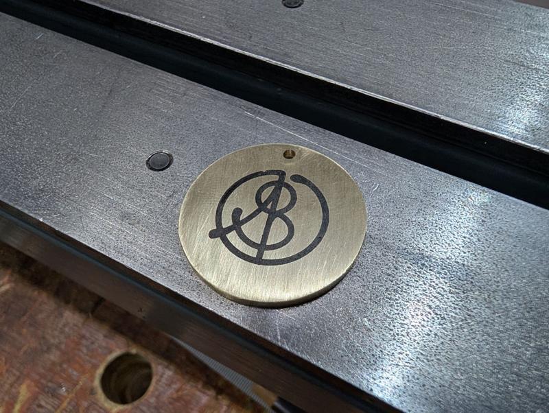
After laser paint removal, the discs looked like this (I think that photo is from ones that hadn't been sanded before painting, but you get the idea):
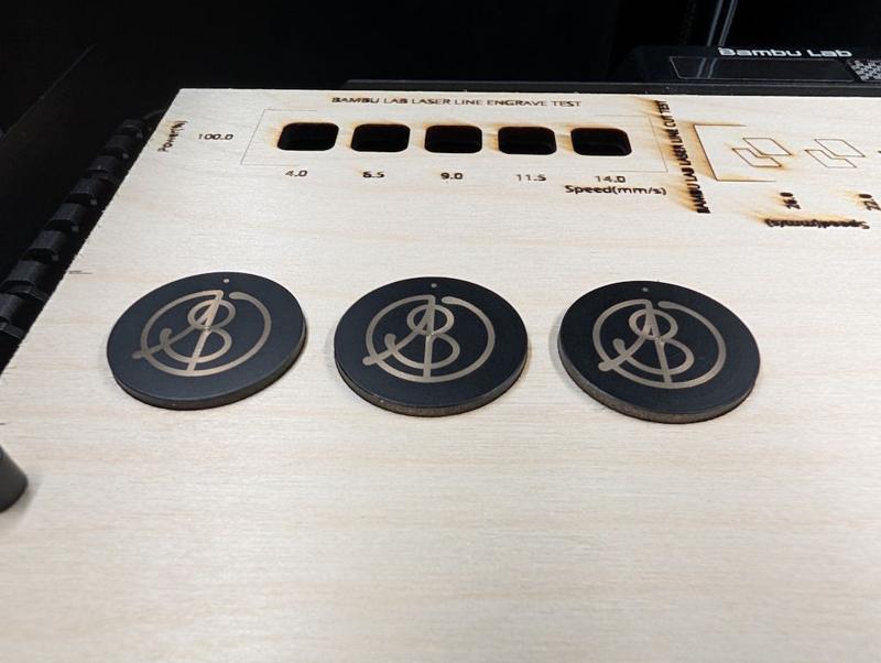
I really like the look of the black discs with the brass showing through, but for this application I don't think the paint will last very long, so I need to do more (which is where it gets complicated!)
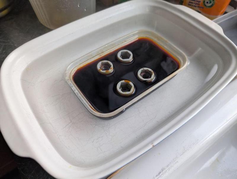
The next job was to assembly my etching kit:
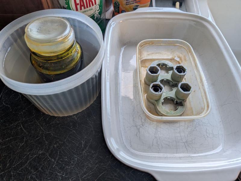
On the left is a jar of ferric chloride etchant, immersed in a pot of boiling water. It's important to loosen the lid of the jar before doing this: the first time I did it the jar was ejected upwards at high speed!
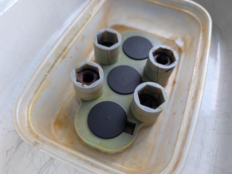
On the right is a little 3D-printed jig to hold the discs. The tall uprights with the hexagonal holes just hold some sacrificial M10 nuts to weigh it down (on the first version I poured the ferric chloride in and it floated).
The discs get placed face-down in the jig so any removed brass can fall away and let the etchant keep working:
It then gets drowned in the warm ferric chloride and I poured another kettle-ful of boiling water into the surrounding dish to help keep it warm:
About six or so sheets of cardboard and then a couple of tea towels were piled on top to help insulate it but that didn't seem worth a photo!
One of the main process variables here is how long it spends in the etchant. After trying quite a few options I settled on a 90 minute etch. Every 30 minutes I took the cardboard "lid" off and gave the jig a little wiggle to shift any stuff that the etchant had removed but had stayed in place.
Out of the etchant, it looks a bit like this:
Acetone removes the paint:
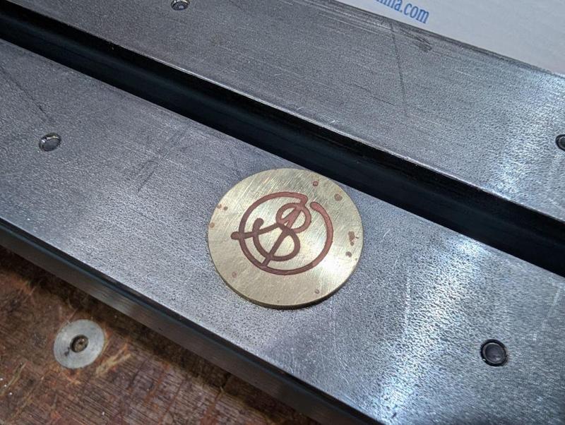
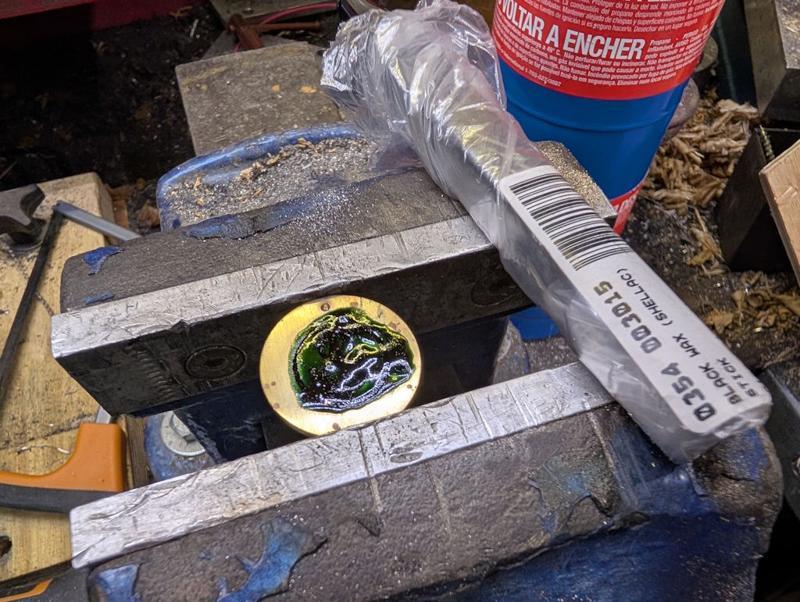
The dot at the top got centre marked and then drilled 2.1 mm. Heat is then applied with a blowtorch:
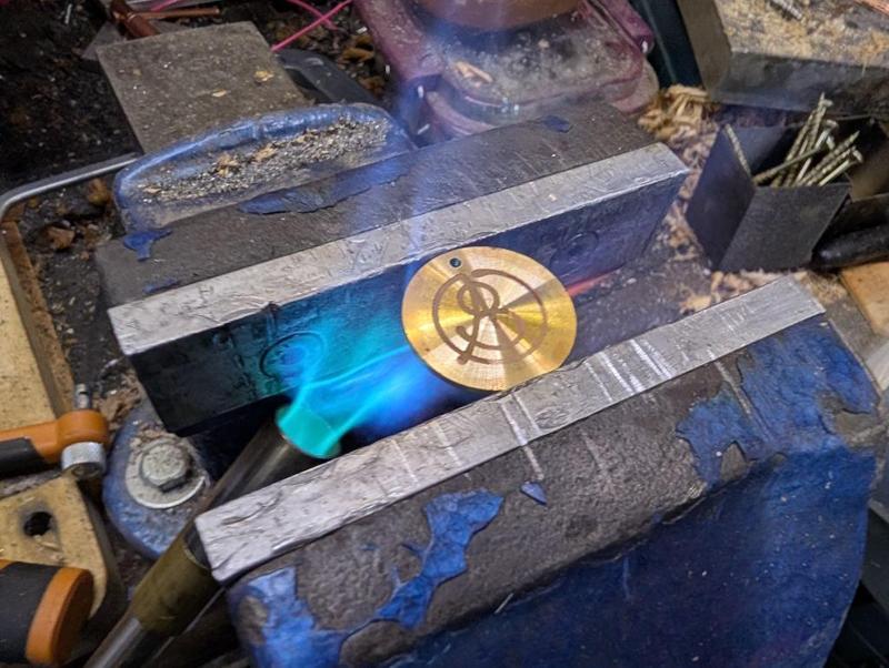
Dial wax (black shellac) is then applied, melting into the etched grooves (note that this one had only been centre marked and not drilled at this point):
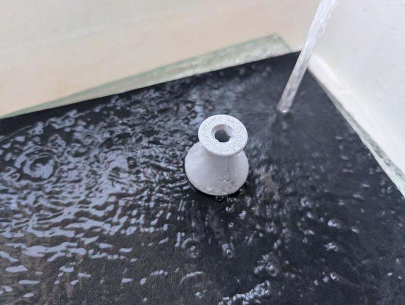
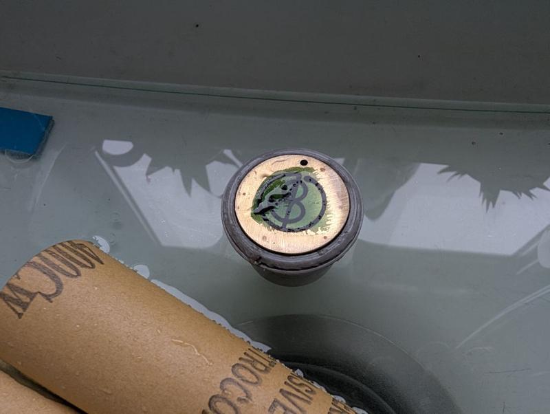
It was then back to the kitchen sink for some more sanding. This time I just did it in still water (but still quite a lot of it) as it seems a bit wasteful having the tap running through the whole process.
I started with 400 grit and got it to this stage:
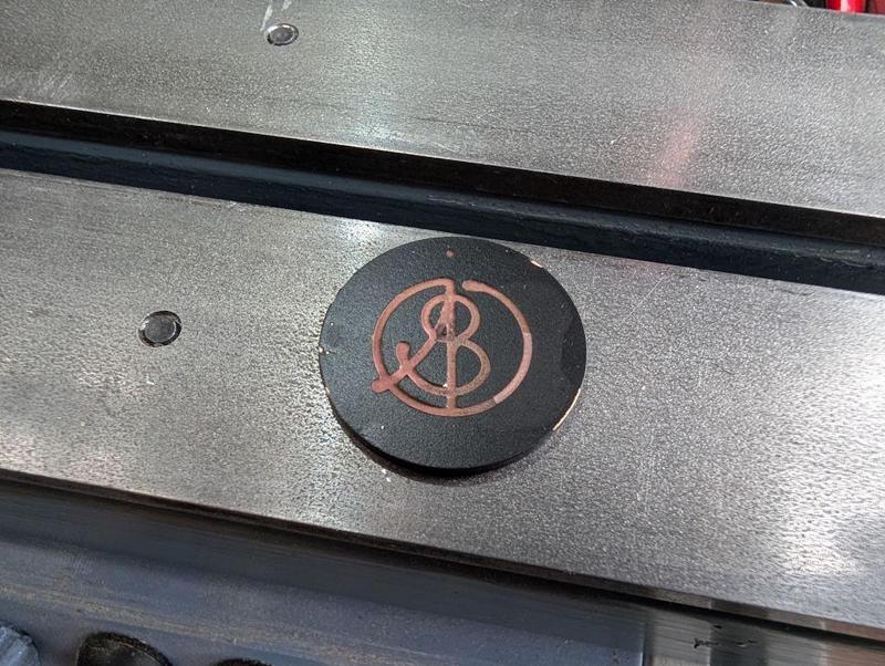
I then used 600 grit for a bit but quite quickly switched to 1200 grit as I didn't want to go too far. The result:
It's a rather matt finish and can be made more glossy, either by sticking in the domestic oven or, as I did, applying some very gentle heat from underneath with a blow-torch:
It's been a lot of work over the last few weekends, but I'm really pleased to have found a process that seems to work. A year or so ago, a very generous member of the MIG-welding forum made some of this sort of thing for me using his CNC engraver. I've still got some of those 20 mm diameter brass discs left but it's much nicer to be able to make them myself as I can customise the size to suit the job in hand (and add features like the dot for carefully aligned drill hole).
When I bought the laser attachment for the 3D printer, I knew it wasn't anywhere near powerful enough to engrave metal directly, but this laser-and-etch process works as a practical alternative that combines the accuracy of the laser with the etch depth of the ferric chloride.
The truth is that I wanted to use it as an opportunity to try something new and it's taken me until today to figure the process out (having started on the 2nd January). If/when I do it again I'll make some minor tweaks but essentially I think it's repeatable finally.
I think the one I've finished today would probably be the fourth complete attempt, but some of the earlier stages were definitely tried out a lot more times than that. Note that the photos below aren't all from the same disc so don't be surprised if things look a bit different from one to the next!
I started with a fairly simple process of taking some 31.75 mm (1¼") brass bar and skimming the outside down to a nice round 30 mm. I then went through a sequence of facing, parting, facing, parting:
That photo was from the first attempt; on later ones I reduced the thickness of the parted off bit. The parted off bits got put back in the lathe using my home-made soft-jaws and each one had its parted face cleaned up with a round-nose tool:
That left me with quite a few discs to play with; this was the set I made for the final round of testing:
The finish I need for the "show" face needs to be smoother than I can get off the lathe. To help with holding the thin parts, I 3D-printed a little holder with a shallow rim:
That didn't print that well (it was with a reel of filament that had been lying out on the table and probably needed to be dried) but it's good enough. With the discs in the recess in the top face as shown in that image, I flipped them both over and rubbed the disc face on wet-and-dry paper under running water (to make sure no brass swarf accumulates and scratches the surface):
I started at 240 grit (on a 12 mm thick sheet of glass) and followed that with 400 grit and 600 grit. If I do it again I might go up to 1200 grit.
I had a scrappy bit of MDF with some blind holes on one side. I drilled them through about 7.5 mm and tapped them M8 before inserting some short cap screws and covering the caps with masking tape. If I do this again, I'll probably ditch the masking tape:
The discs got placed (sanded face down for the first coat) on the MDF, which was placed on a cardboard base (in the dining room for warmth reasons) and surrounded on three sides with more cardboard. The discs then got four coats (15 minutes apart) of Screwfix black spray paint:
After allowing about 8 hours for the paint to dry, I flipped them over and gave the sanded faces four coats. I later noticed that the masking tape had left a slight residue on the sanded face. It wasn't a big deal in the end, but I think if I do it again I'll paint the show face first and then (carefully) place that on the screw heads (possibly after skimming the screw heads on the lathe to minimise the chance of scratches in the paint).
Here are a batch of 12 discs after the paint had dried:
I'd also painted a bit of brass sheet and I used that to calibrate the laser attachment on my 3D-printer:
I did find the laser calibration settings depended (unsurprisingly) on the number of coats of paint, as well as on the thickness of each layer. The conclusion I came to was that increasing the number of passes (i.e. the number of times the laser engraves the image) was a good thing. More passes increases the likelihood of getting rid of all the paint but allows the power to be kept low so that there's less chance of removing paint in the wrong places.
I've found the accuracy of the camera used for alignment of the printer's laser is pretty awful, so I needed a way to deal with that. I started by cutting some 30 mm discs out of 3 mm thick plywood using the laser. I then fitted a sheet of 4 mm plywood and ran the laser job with the pattern I wanted as a laser fill (i.e. engrave) and the outline as a laser cut. That gave me some 30 mm pockets in the 4 mm plywood, into which I dropped the 3 mm thick plywood discs, giving me some 1 mm deep pockets.
The 30 mm diameter painted discs then got dropped into the pockets and the program run again without moving anything (thereby guaranteeing that the laser job would be in the right place). I'd configured the profile such that a "laser cut" on the brass pieces was at minimum power, high speed and with a 2 mm cut off-set. That meant that, after doing the engraving, the laser "cut" program ran in a circle over the plywood (rather than the brass) with so little power that it didn't even mark the plywood, let alone the brass.
That configuration meant that I could use the same program (with laser fill and laser "cut") on the plywood and the painted brass without any alignment worries and without inadvertently removing any paint from the rim of the brass discs.
After laser paint removal, the discs looked like this (I think that photo is from ones that hadn't been sanded before painting, but you get the idea):
I really like the look of the black discs with the brass showing through, but for this application I don't think the paint will last very long, so I need to do more (which is where it gets complicated!)
The next job was to assembly my etching kit:
On the left is a jar of ferric chloride etchant, immersed in a pot of boiling water. It's important to loosen the lid of the jar before doing this: the first time I did it the jar was ejected upwards at high speed!
On the right is a little 3D-printed jig to hold the discs. The tall uprights with the hexagonal holes just hold some sacrificial M10 nuts to weigh it down (on the first version I poured the ferric chloride in and it floated).
The discs get placed face-down in the jig so any removed brass can fall away and let the etchant keep working:
It then gets drowned in the warm ferric chloride and I poured another kettle-ful of boiling water into the surrounding dish to help keep it warm:
About six or so sheets of cardboard and then a couple of tea towels were piled on top to help insulate it but that didn't seem worth a photo!
One of the main process variables here is how long it spends in the etchant. After trying quite a few options I settled on a 90 minute etch. Every 30 minutes I took the cardboard "lid" off and gave the jig a little wiggle to shift any stuff that the etchant had removed but had stayed in place.
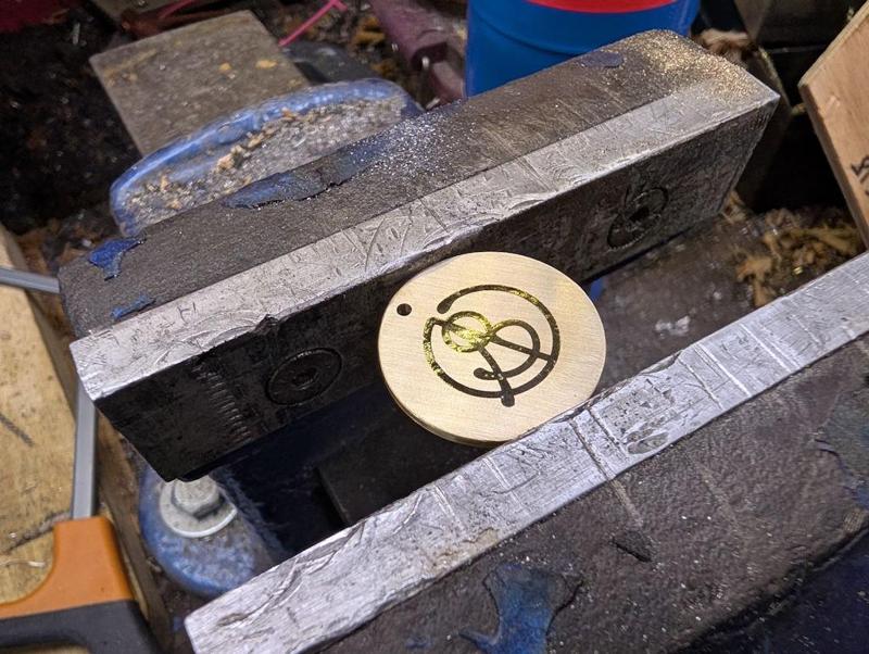
Out of the etchant, it looks a bit like this:
Acetone removes the paint:
The dot at the top got centre marked and then drilled 2.1 mm. Heat is then applied with a blowtorch:
Dial wax (black shellac) is then applied, melting into the etched grooves (note that this one had only been centre marked and not drilled at this point):
It was then back to the kitchen sink for some more sanding. This time I just did it in still water (but still quite a lot of it) as it seems a bit wasteful having the tap running through the whole process.
I started with 400 grit and got it to this stage:
I then used 600 grit for a bit but quite quickly switched to 1200 grit as I didn't want to go too far. The result:
It's a rather matt finish and can be made more glossy, either by sticking in the domestic oven or, as I did, applying some very gentle heat from underneath with a blow-torch:
It's been a lot of work over the last few weekends, but I'm really pleased to have found a process that seems to work. A year or so ago, a very generous member of the MIG-welding forum made some of this sort of thing for me using his CNC engraver. I've still got some of those 20 mm diameter brass discs left but it's much nicer to be able to make them myself as I can customise the size to suit the job in hand (and add features like the dot for carefully aligned drill hole).
When I bought the laser attachment for the 3D printer, I knew it wasn't anywhere near powerful enough to engrave metal directly, but this laser-and-etch process works as a practical alternative that combines the accuracy of the laser with the etch depth of the ferric chloride.

Why do you need so many supermarket trolley tokens?")
")
NickM
Old Oak
That's fun! It opens up lots of opportunities.
Dr.Al
Old Oak
I posted this on my website yesterday but didn't get round to sticking it onto the forum so I apologise for the delay!
The last, relatively simple, job for the tommy bar hole cover was to fit it. I used an M2 × 16 mm cap screw, two washers and two nuts. I'd have preferred a nyloc nut, but I don't think you can get them for an M2 screw. Fitting was a little awkward just because of the tiny 4 mm nuts but it didn't take long.
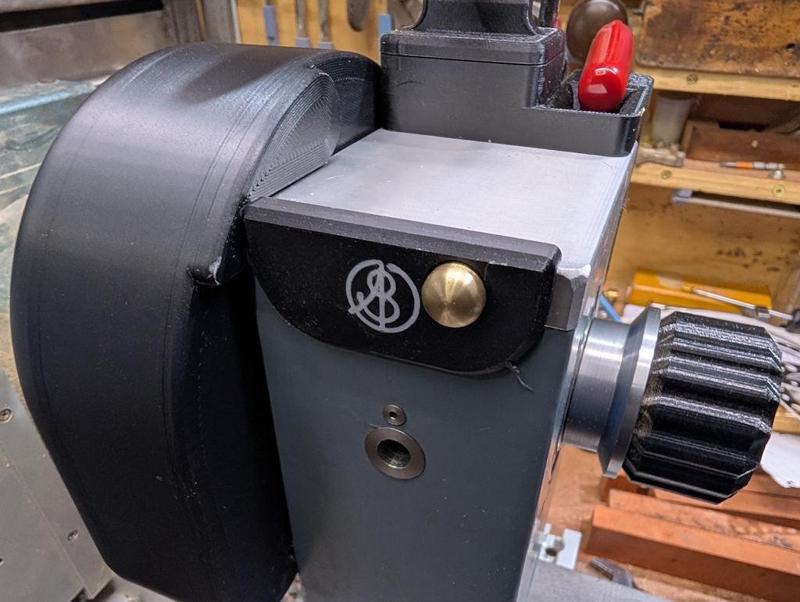
I also replaced the 3D-printed slide cover with a plain one (that I'd printed at the same time). It seems a bit daft having the logo on there twice. I put the logo on the original slide cover for two reasons. The first reason was that I wanted to try printing the logo and seeing how it would look. However, the main reason was that I wasn't convinced I'd manage to make the brass/wax logo and wanted to have my logo on the lathe in the event that I gave up and used a plain metal disc.
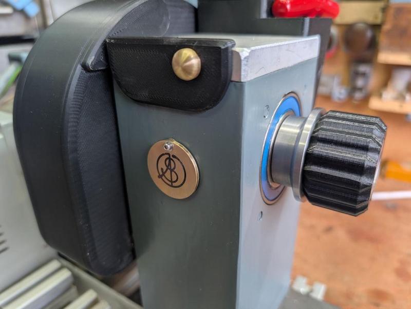
Here's the disc swung out of the way allowing access to the hole:
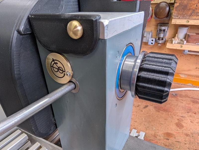
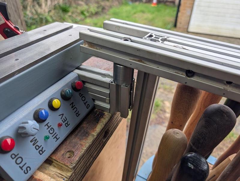
Finally for this (possibly final?) round of lathe upgrades was a simple job: adding another mount for the Lazy Susan at the tail end of the bed. There's one already at the headstock end but sometimes the tools get in the way when, e.g. shaping the outside of a bowl, so it's nice to be able to move it to the back end. At the moment I just drop it into one of the dog holes in the bench, but I can see the twisting force wearing the dog hole out so I thought I'd add a steel mount to the lathe structure:
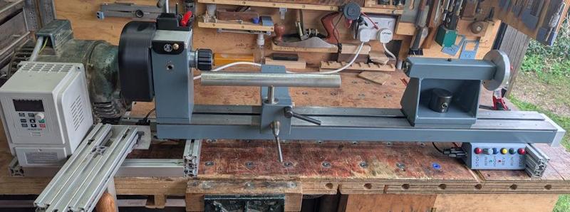
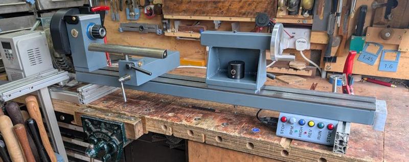
With that, the lathe is as complete as it's going to be. I took some photos because it seemed like a good idea. Note that the photos were taken before I fitted the tail end mount for the Lazy Susan: after fitting that the heavens opened and the sky went really dark and I didn't think I'd get a very good photo!
The last, relatively simple, job for the tommy bar hole cover was to fit it. I used an M2 × 16 mm cap screw, two washers and two nuts. I'd have preferred a nyloc nut, but I don't think you can get them for an M2 screw. Fitting was a little awkward just because of the tiny 4 mm nuts but it didn't take long.
I also replaced the 3D-printed slide cover with a plain one (that I'd printed at the same time). It seems a bit daft having the logo on there twice. I put the logo on the original slide cover for two reasons. The first reason was that I wanted to try printing the logo and seeing how it would look. However, the main reason was that I wasn't convinced I'd manage to make the brass/wax logo and wanted to have my logo on the lathe in the event that I gave up and used a plain metal disc.
Here's the disc swung out of the way allowing access to the hole:
Finally for this (possibly final?) round of lathe upgrades was a simple job: adding another mount for the Lazy Susan at the tail end of the bed. There's one already at the headstock end but sometimes the tools get in the way when, e.g. shaping the outside of a bowl, so it's nice to be able to move it to the back end. At the moment I just drop it into one of the dog holes in the bench, but I can see the twisting force wearing the dog hole out so I thought I'd add a steel mount to the lathe structure:
With that, the lathe is as complete as it's going to be. I took some photos because it seemed like a good idea. Note that the photos were taken before I fitted the tail end mount for the Lazy Susan: after fitting that the heavens opened and the sky went really dark and I didn't think I'd get a very good photo!
John Brown
Sapling
Awe inspiring...
Dr.Al
Old Oak
duke
Old Oak
Your not the only one Mike, count me in also.
NickM
Old Oak
Very good. Bravo!
Cabinetman
Sequoia
- Joined
- Oct 11, 2020
- Messages
- 5,225
- Reaction score
- 994
- Location
- Lincolnshire Wolds + Massachusetts
- Name
- Ian
And me ( the ignoramious bit) nice touches Al.
Dr.Al
Old Oak
It's quite an interesting process. I've tried it quite a few times with mixed results.Superb. I always wanted to try etching.
The first time I did it was for a gift for a friend of Carolyn's. The friend (Hayley) lived in Finland and had been planning to fly to her home country (South Africa) for a half-marathon but for various reasons couldn't go. She decided to run the half-marathon in Finland on her own at the same time as the "real" one. I made her a medal, which was given to her as she crossed the finish line (out of Aluminium Bronze):


That one was done (if memory serves me correctly) with "press'n'peel" paper, which you print on with a laser printer and then transfer to the part using a domestic iron. It's quite a cheap and simple way to get started, although you do need a laser printer and the process of ironing the pattern onto the part is quite fussy.
I've since also had some trials with photolithography, which uses an acetate sheet (again printed on a laser printer) and some photo-sensitive paper. That one is also fussy as you have to iron the photo-sensitive paper on (and you have to do it in the dark!)
Using the laser to do the pattern marking saves all of that embuggerance with an iron (and removes the need for a laser printer, although it adds the need for a laser engraver!). Nevertheless, it's nice that there are quite a few different options out there.
Clickspring has an excellent video showing the photolithography approach, which is well worth a watch (as is the rest of that series).
Accipiter
Sapling
- Joined
- Oct 16, 2025
- Messages
- 347
- Reaction score
- 289
- Location
- Frome, Somerset
- Name
- Frank
- LOCATION
- Somerset
 . I can fully understand what Mike G means...
duke
Old Oak
Wow, your lathe is looking nice.
Lurker
Old Oak
Excellent Al.