• Hi all and welcome to TheWoodHaven2 brought into the 21st Century, kicking and screaming! We all have Alasdair to thank for the vast bulk of the heavy lifting to get us here, no more so than me because he's taken away a huge burden of responsibility from my shoulders and brought us to this new shiny home, with all your previous content (hopefully) still intact! Please peruse and feed back. There is still plenty to do, like changing the colour scheme, adding the banner graphic, tweaking the odd setting here and there so I have added a new thread in the 'Technical Issues, Bugs and Feature Requests' forum for you to add any issues you find, any missing settings or just anything you'd like to see added/removed from the feature set that Xenforo offers. We will get to everything over the coming weeks so please be patient, but add anything at all to the thread I mention above and we promise to get to them over the next few days/weeks/months. In the meantime, please enjoy!

Like the ocean under the moon

Thank you Andy & no, I didn't know any of that. I picked brass for the simple reasons that it's tougher than wood but a heck of a lot easier to work than steel.

My little block plane has a brass sole as well & I was just doing the same thing without thinking about it much.

I have no plans for dealing with it so I guess it'll probably have to be an experiment to see if it really matters. I guess I could try to attach a thin sheet of shim steel to the bottom (somehow) if it proves to be an issue 🤷‍♂️
 
Last edited:
Ok, I wouldn't be surprised if it's something that used to be a problem with older varieties of castable brass but isn't with modern strip/sheet.
 
Cracking work Sir. I like the use of the digital angle finder, much easier than sine bars.
 
This morning was a bit dull if I'm honest. I started by hacksawing off the excess on the home-made screw:

2026-04-06-01-saw-off-excess_600.jpg


The body then went in the jaws of my portable workbench (to raise it up a bit and save my back) for the heads of the screws to be filed down:

2026-04-06-02-filing_600.jpg


I used a couple of punches (one with a flat end and one with a domed end) along with a hammer to mash the heads up in order to try to merge the screw material with the base material:

2026-04-06-03-mashing_600.jpg


It then went back in the portable workbench vice for more filing (with some finer files):

2026-04-06-04-more-filing_600.jpg


The biggest flat surface I have is the bandsaw table, so I clamped some 80 grit sandpaper to that and started rubbing the base on it, regularly cleaning off the dust with a brass brush. It was immediately obvious that the low points were where the screws were so I guess the screws had ever-so-slightly deformed the brass when they were tightened.

2026-04-06-05-sanding_600.jpg


After doing that for a while, I remembered that I had a roll of 60 grit sandpaper so I switched to that:

2026-04-06-06-more-sanding_600.jpg


After quite a lot of back and forth on the sandpaper I eventually decided I'd had enough and stopped when it looked like this:

2026-04-06-07-that-will-do-for-now_600.jpg


I didn't want to go too far given that the lever cap might distort the shape a little so ideally it'll be flattened with the lever cap fitted. Also, I was fed up of sanding brass.

The brass screws hadn't disappeared as much as I'd hoped. Here are the two at the front:

2026-04-06-08-not-great_600.jpg


The two in the middle are better:

2026-04-06-09-not-bad_600.jpg


The two at the back aren't bad:

2026-04-06-10-somewhere-in-between_600.jpg


I haven't decided how much to do about those yet. They won't affect the operation of the plane so I could decide just not to worry about them. I could also just see what they look like when I've sanded them a whole lot more. Another option is to drill and taper-ream some little holes for tapered pins, fit the pins and then mash the pins to fill in some of the gaps. That's something I'll ponder on over the next week or two.

In the meantime, the plane went back into the portable workbench vice for more filing (which actually felt quite enjoyable after the sanding!)

2026-04-06-11-more-filing_600.jpg


The ends got filed too:

2026-04-06-12-more-filing_600.jpg


It was then time to do some more filing, this time for the mouth opening:

2026-04-06-13-more-filing_600.jpg


That's quite a smooth file (probably 2nd cut at a guess), but it was the coarsest 4 mm thick one I could find: all my coarser ones are 5 mm or more and that would open up the gap too much.

I worked at the bottom surface (which isn't that critical as it's just the opening behind the blade) and kept going until it was parallel with the bed. I then rounded over the very tip as I didn't want a sharp brass point behind the blade.

2026-04-06-14-stop-for-the-morning_600.jpg


At that point it was time for lunch. We spent the afternoon out so I haven't done any more today.

I think the next job probably needs to be making the lever cap, which I haven't figured out yet. Ideally, I'd make it out of something like 10 × 50 mm brass flat bar, but I haven't got any and it seems to be rather expensive stuff to buy.

One day I'd like to get set up for brass casting. I've got loads of scrap brass stored away for when I eventually do and if I was equipped for that I could have a go at casting myself some thick flat bar. That's not an option at the moment sadly.

Another option is to make it out of stainless steel. That would have the advantage I could buy some thinner material and build up the thickness where required by welding pieces together.

There are probably plenty of other options too, but I haven't thought of them yet!
 
This week felt like a long one, despite being only three days of work. As a result, I had a very slow start to the day and, after a walk out for lunch, I finally made it to the workshop at about 2pm. Having finished the lower surface of the brass opening, I could start working on the front of the mouth. As the file doesn't need to lie at the 36° bed angle, I could use a thicker file, which allowed me to use one of my coarser ones:

2026-04-10-01-opening-front-of-mouth_600.jpg


This bit was quite slow going as I don't want to open the mouth out too much (and have a big gap in front of the blade). The only way I could think to do it was to file a tiny bit, check with the blade, file a tiny bit, check with the blade etc. As soon as the blade protruded out of the bottom I stopped.

2026-04-10-02-poking-through_600.jpg


At the moment the opening might be a bit on the small side, but I can open it up later if necessary and if I do any more flattening of the bottom it might have an effect so it's better to stop now.

I mentioned in an earlier post that the blade seemed to be poking out too far (when I tested it before fitting the brass base). Unfortunately, the extra base thickness from the brass wasn't enough to deal with the issue. With the blade fitted and flush with the bottom of the plane, this is what the pocket looks like:

2026-04-10-03-hole-in-wrong-place_600.jpg


As you can see, the hole for the threaded rod is slightly under the blade. This is what the CAD model looks like in the same position (and with the cap iron fitted):

2026-04-10-06-cad-model_600.jpg


It looks like I've somehow drilled the hole for the mounting screw about 5 mm further forward than I should have. The CAD model went through quite a lot of changes (moving things back and forward by, not entirely coincidentally, about 5 mm) as I was in the process of making the plane body. I suspect I made the plane body templates from an older version of the model and the blade and cap iron from the newer version.

With the blade pulled all the way back against a bit of 10 mm threaded rod in that hole, it'd extend much too far for a sensible cut depth, so I need to do something about it. The cap iron isn't too much of a problem as I can easily extend the slot a bit lower. The blades are more of an issue and I've really only got two options:

  1. Stick them back in the heat treatment oven to anneal them, then extend the slot, then harden, temper and flatten them again.
  2. Grind more off the tip to shorten the blade.

To make the problem slightly smaller than it was, I grabbed an off-cut of 303 stainless steel out of the drawer and turned a custom bit of threaded rod:

2026-04-10-04-custom-screw_600.jpg


That's got an M8 thread on the left-hand end, then a 6 mm smooth shank and finally an M6 thread. It screws into the M8 pocket in the body like this:

2026-04-10-05-screw-fitted_600.jpg


That allows me to use an M6 knurled nut instead of the M8 one I'd initially planned and allows the blade to move 1 mm further up into the body. It's still not quite enough to withdraw the blade fully, but it's enough that it could be usable as a smoothing plane. I'll regrind the tips of all the blades to bring the cutting edge back a bit further and that should allow the blade to (just) be fully retracted. At least with the 6 mm shank I haven't got very much to grind off. Somewhat annoying but not the end of the world.
 
I've reground the tip of (and hence shortened slightly) one of the blades and resharpened it. I'll do the other two another time. I also put the lever cap back in the mill vice and extended the slot by 5 mm:

2026-04-10-07-extending-slot-in-lever-cap_600.jpg


With those two modifications made, the blade can be fully retracted (with room to spare). While I've still got a long way to go (with the biggest jobs being the lever cap and the handle), I decided to try fitting the blade using a penny washer and a nut to hold it in place and a spanner and hammer as adjustment tools:

2026-04-10-08-temporary-fitment-with-spanner-and-hammer_600.jpg


With it roughly aligned with the hammer, I could have a quick play with a scrap of cherry:

2026-04-10-09-playing_600.jpg
 
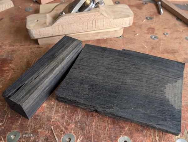
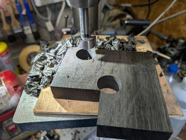
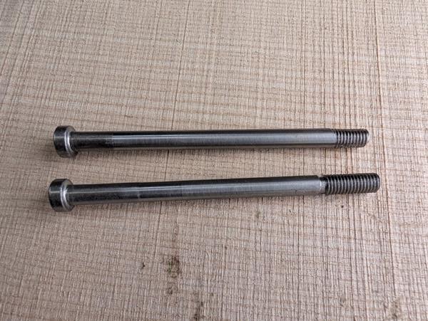
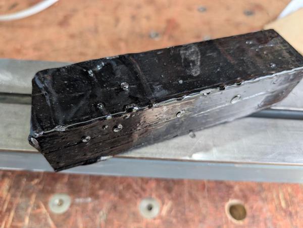
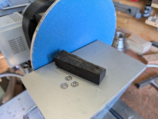
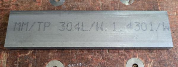
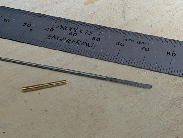
Today's been a bit of a "bitty" day with lots of sessions in the workshop and various unrelated obligations in between. Nevertheless, I'm pleased with the progress I've made. The project for today was to work on the lever cap. It started off as this length of 10 × 50 mm 304 stainless steel:

2026-04-11-01-stock-for-lever-cap_600.jpg


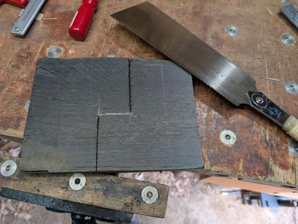
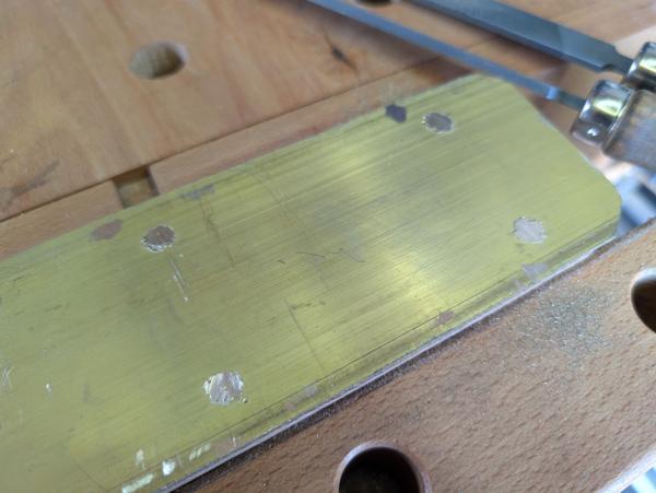
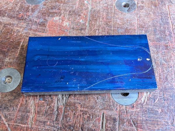
That got chopped in half, daubed in Dykem and marked (by tracing round a 3D-printed template):

2026-04-11-02-chopped-in-half-and-marked_600.jpg


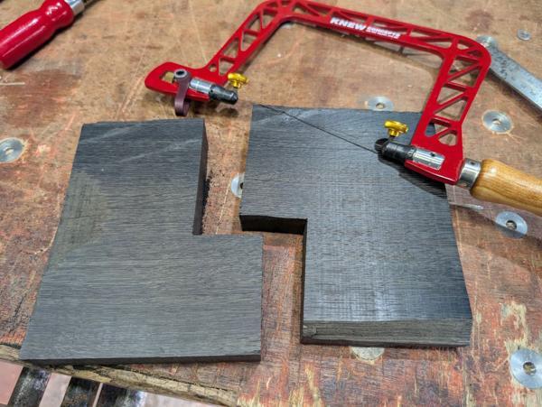
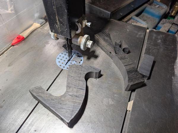
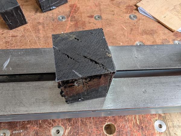
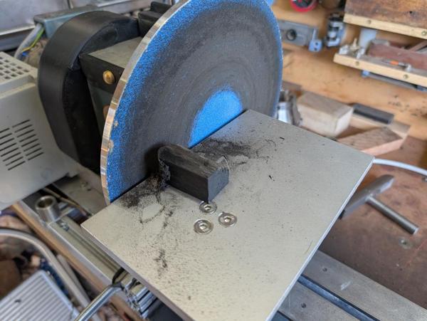
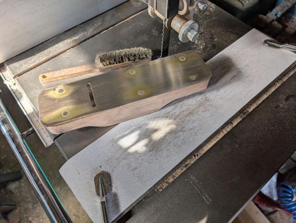
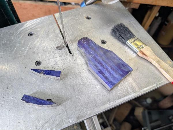
Milling stainless steel isn't my favourite thing to do, so to make life a bit easier for my mini milling machine, I cut as much off as possible with the bandsaw:

2026-04-11-03-rough-sawn_600.jpg


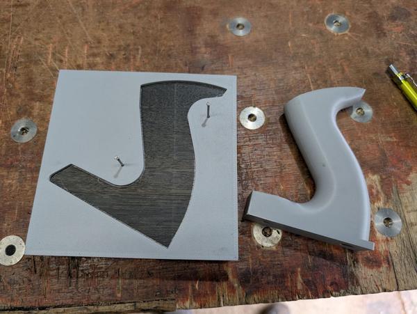
After fitting the rotary table to the milling machine and centring the axis on its centre, I used this 3D-printed set-up aid to put the part into the right place on the table:

2026-04-11-04-printed-set-up-aid_600.jpg


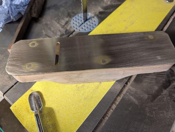
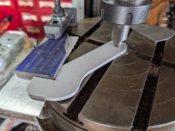
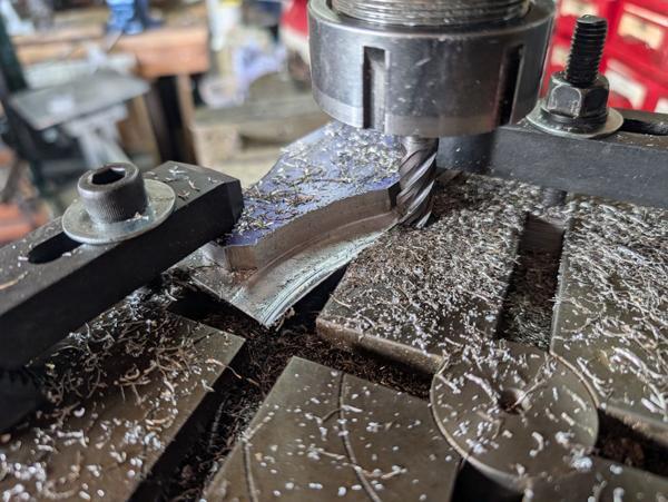
After adding a second clamp, I could then mill the 80 mm radius curve. After turning the part round and flipping the set-up aid over, I could also do the other side:

2026-04-11-05-cutting-curve_600.jpg


The thin aluminium sheet underneath the part is there to allow me to cut all the way through the lever cap without risking damage to the rotary table's surface.

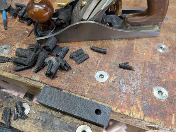
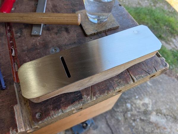
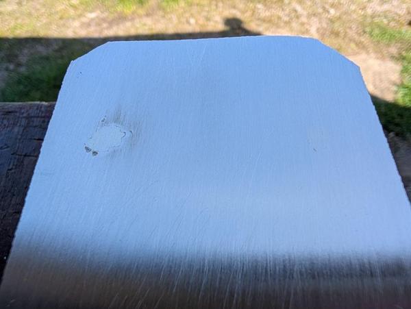
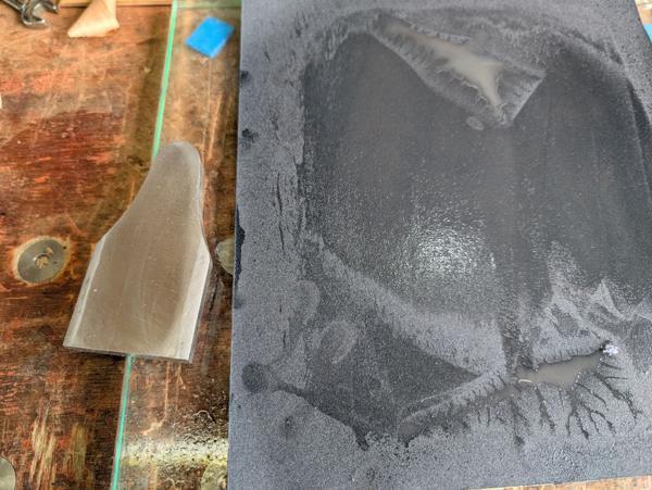
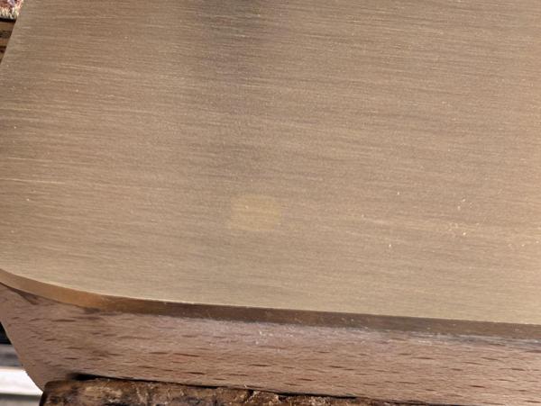
I picked a side to be the top and did a bit of flattening on some wet-and-dry paper, starting with 120 grit and then progressing to 240 grit:

2026-04-11-06-flattening-top-side_600.jpg


I'm not aiming for a super high polished finish, I just wanted a fairly flat surface for what I was about to try next. You'll notice from the photo that I haven't flattened it all the way to the edges. It's only the centre bit that mattered to me so that's fine.

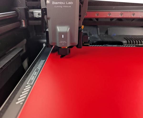
Last year I bought a new 3D printer. As well as being able to 3D print, it has a laser attachment (which I've used mostly for engraving my logo into some bits of wood but also used to ablate paint on brass so that I could then acid etch my logo into brass discs) and a vinyl cutting module. Up until today I've never tried the vinyl cutter and I thought this would be a good excuse to do so.

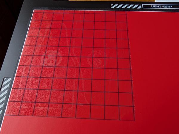
After going through the various calibration routines suggested, I placed a sheet of matt removable vinyl onto the bed and set the cutter going:

2026-04-11-07-vinyl-cutting_600.jpg


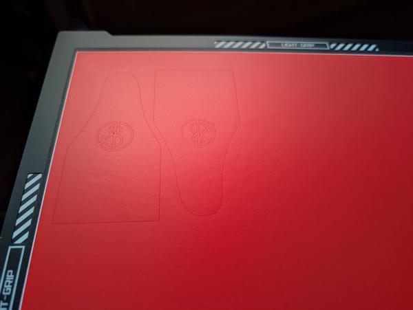
This is what it looked like.

2026-04-11-08-vinyl-cut_600.jpg


You may have to squint to see the outline, but it's there! I did two in case the first one didn't work.

I'd also got some so-called "transfer tape", which is used to transfer the cut vinyl pattern onto the end part. I placed that over the entire cut area (with hindsight, it would have been better to "weed" out the bits I didn't want before applying the tape, but it worked well enough).

2026-04-11-09-transfer-tape_600.jpg


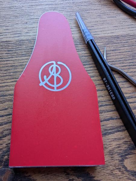
After transferring the vinyl onto the lever cap, I weeded out the unwanted bits:

2026-04-11-10-transferred-and-weeded_600.jpg


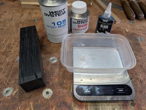
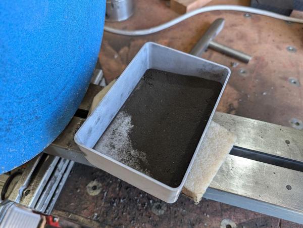
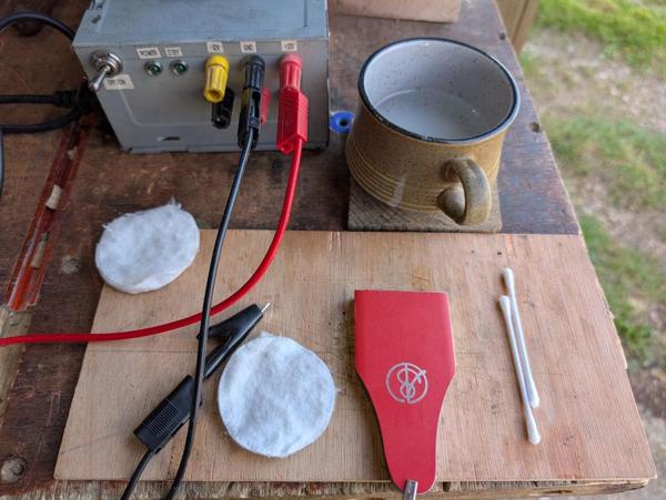
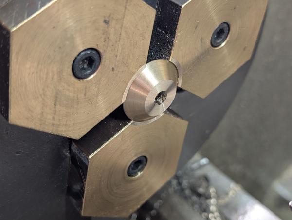
It was then time to try another technique I've ever used: salt water electro-etching. This is the kit I assembled:

2026-04-11-11-ready-for-electro-etching_600.jpg


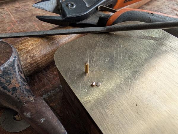
In the top-left is a home-made bench power supply (it's just an old PC power supply with the various voltages brought out to 4 mm sockets). In the top-right is salt water (brine) mix, which is made simply by putting some water in a cup and then adding table salt until it stops dissolving. The cotton buds and cotton buds are options for applying the salt and electricity.

The positive voltage terminal (I used 12 V but I've read that a 9 V PP3 battery works fine) gets connected to the part and then the negative (0 V) terminal is applied to the salt solution. Most guides I'd read on this suggested using the cotton buds, dipping in salt water and then holding the cotton bud with the crocodile clip. That worked but seemed quite slow and awkward and I managed to knock the tiny bit of vinyl in the middle of the "A" part of my logo off with the cotton bud, which was a shame but not the end of the world.

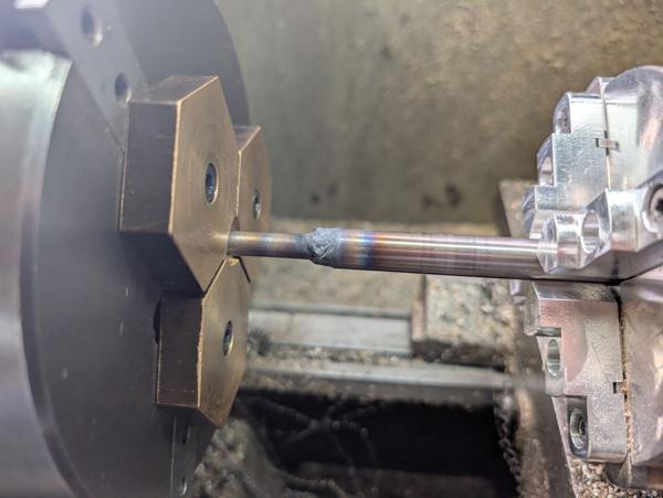
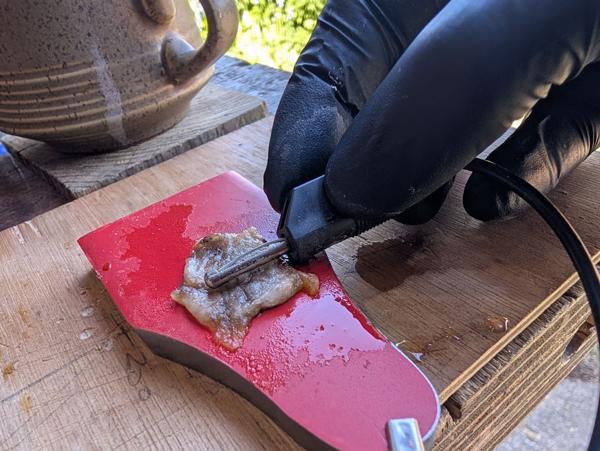
I found a better method was to use a piece of cotton pad, saturated in the salt water solution and rubbed with the side of the 4 mm banana plug:

2026-04-11-12-etching_600.jpg


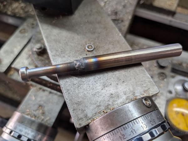
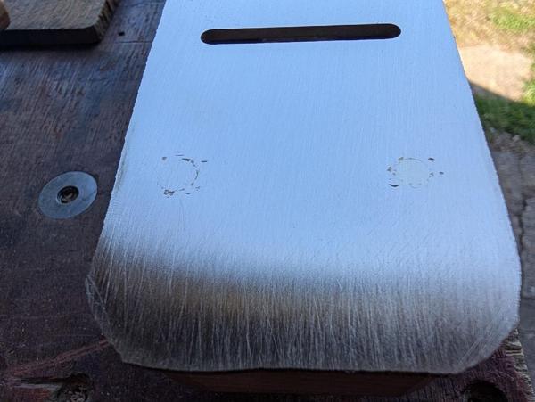
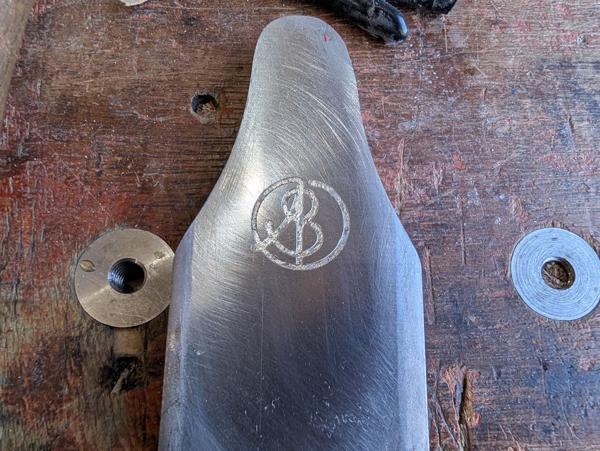
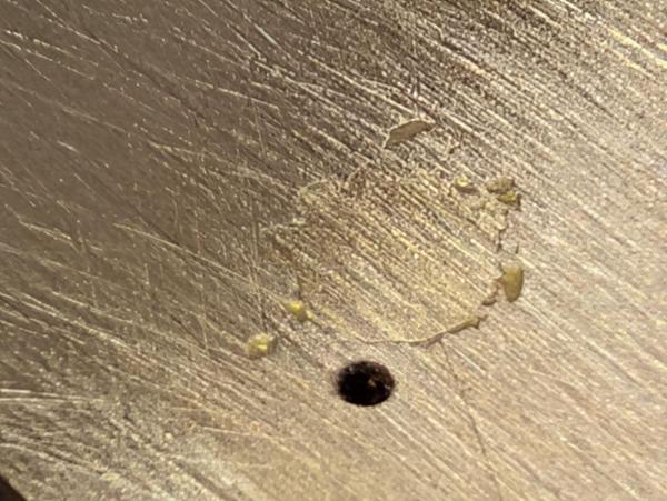
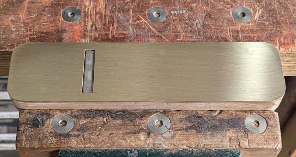
After 5 minutes or so of etching, I rinsed the part in water and peeled off the vinyl:

2026-04-11-13-etched_600.jpg


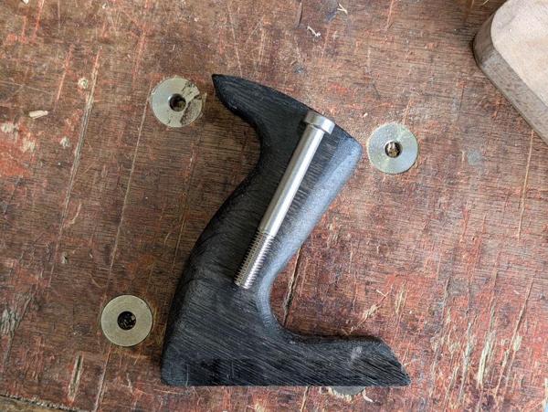
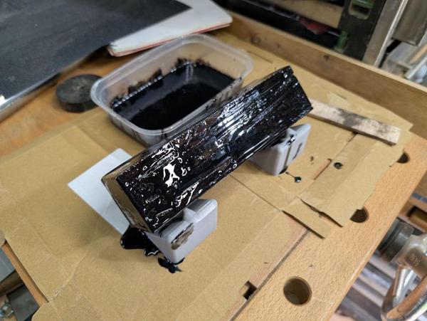
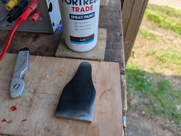
It then got a couple of coats of black matt spray paint...

2026-04-11-14-sprayed_600.jpg


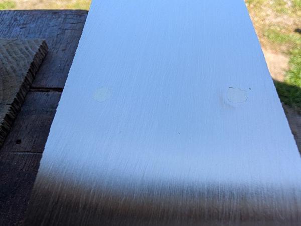
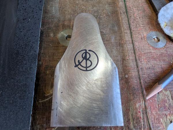
... before being sanded again:

2026-04-11-15-sanded_600.jpg


There's still quite a lot of work to do on this part and usually I'd do things like logo marking after everything else was finished, but I wasn't very confident in my likelihood of success so I decided to do the etching before going too far and that way I could sand it off or start again without having lost too much time. In the end it worked well enough I think, so I could continue.

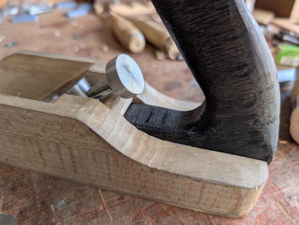
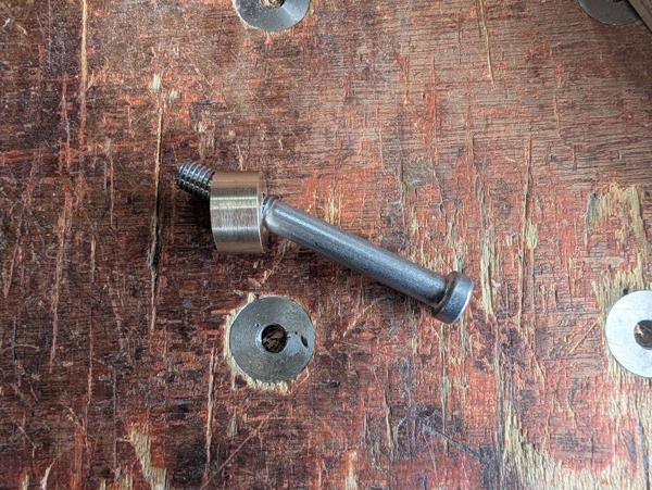
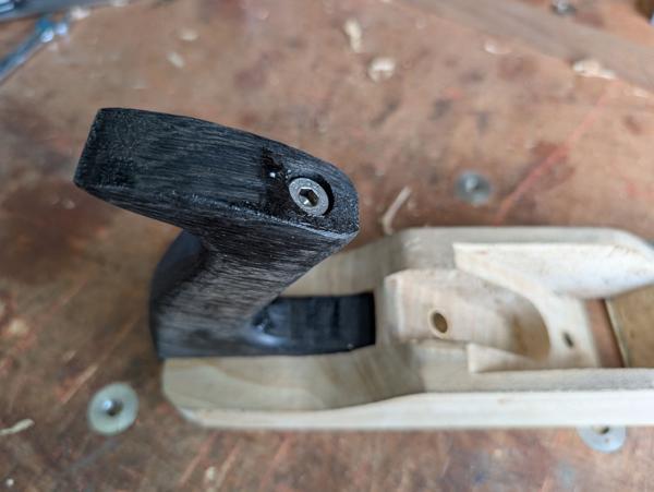
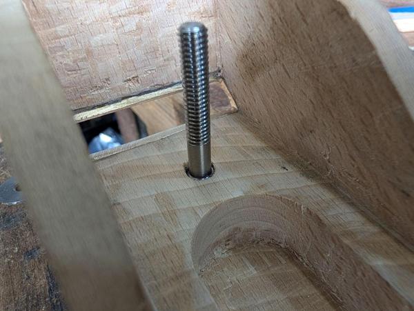
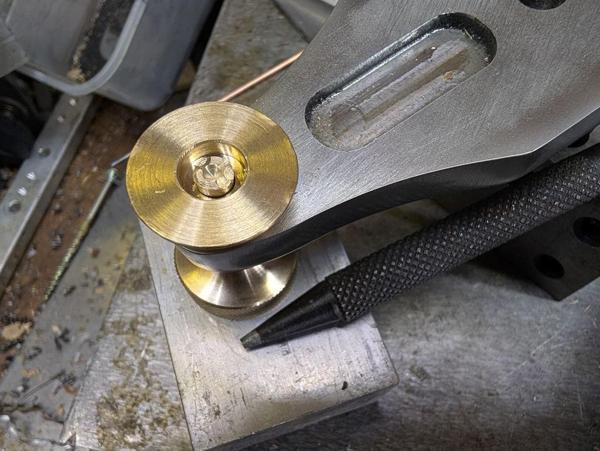
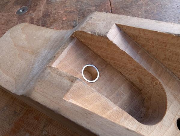
I'm going to use a small pad under the lever cap screw to spread the pressure from the screw on the cap iron. The design will hopefully be similar to the ones used on the Veritas low angle planes. That pad means that, even with the screw fully retracted, the lever cap will be at an angle to the cap iron and blade. That angle has a fringe benefit that it'll provide some of the required clearance over the "nut" that's built into the cap iron.

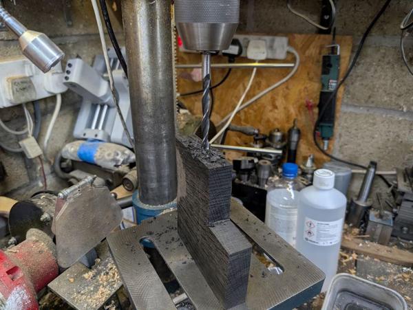
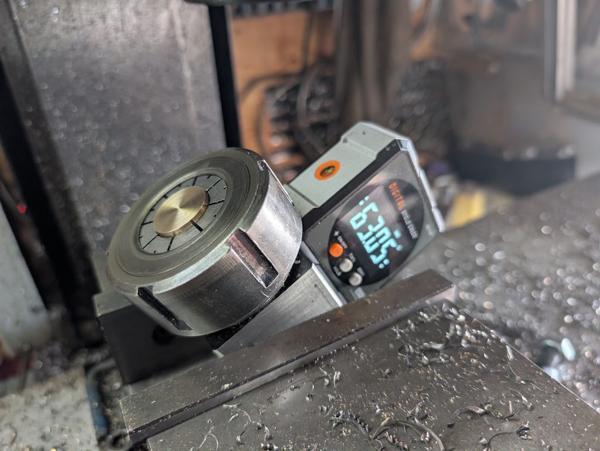
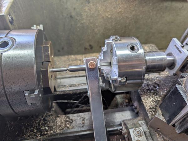
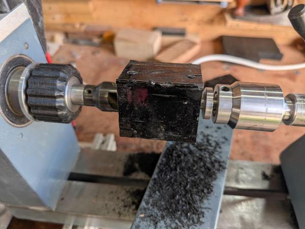
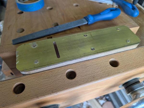
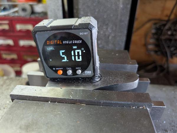
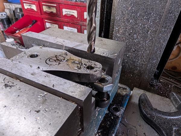
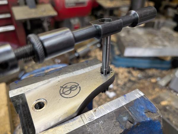
Since the lever cap will always be at a slight angle, I figured I might as well drill the two holes that go through it an angle as well. The angle of the holes won't be perfect (as the lever cap angle will vary with how far the screw moves), but it'll be better than having it square to the lever cap's face. As before, I set the angle in the milling vice with a digital angle gauge, aiming for 5° but not being too fussy:

2026-04-11-16-angle-for-drilling_600.jpg


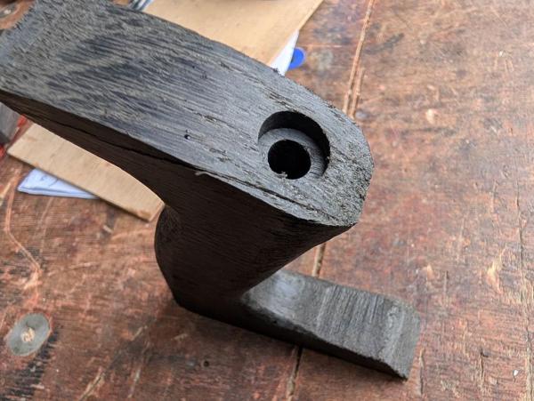
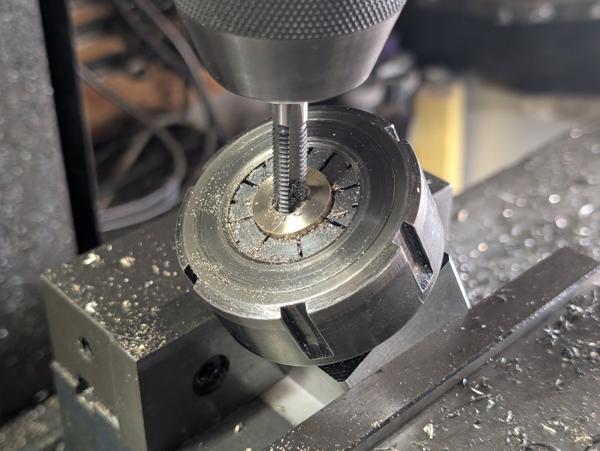
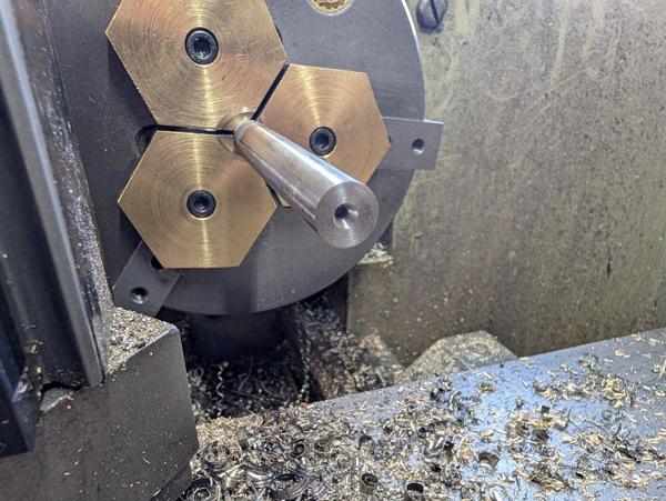
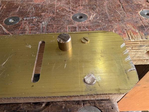
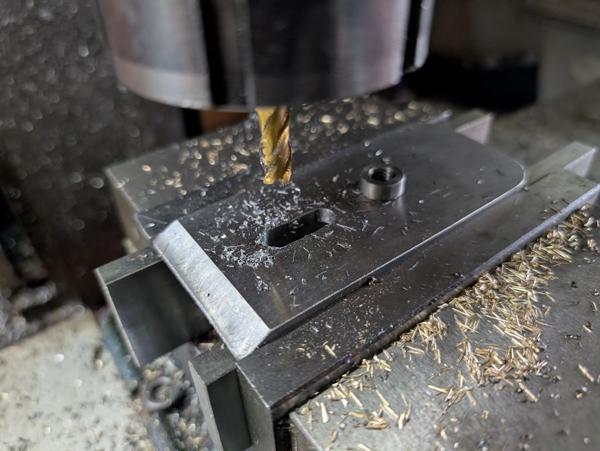
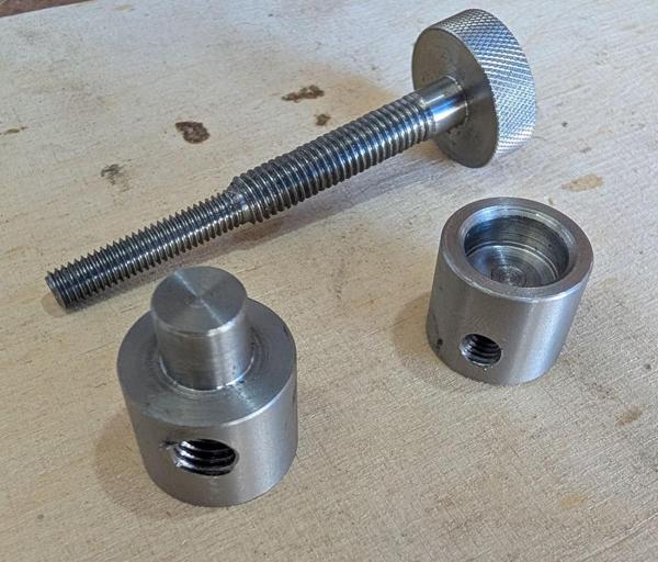
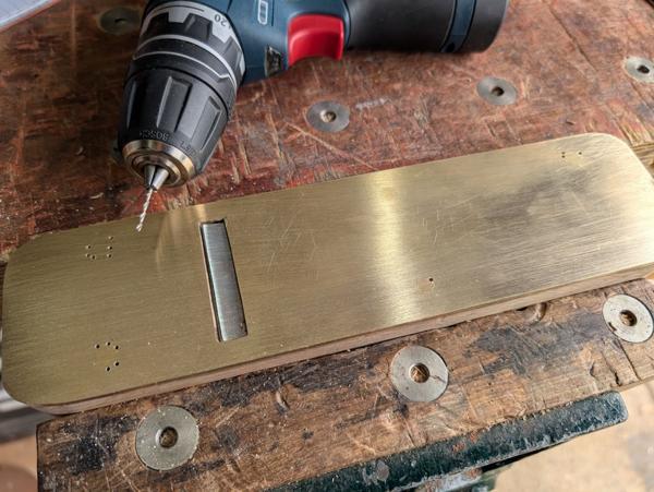
After adding a cap screw and nut as a jack on the outer end for a bit of extra support, I drilled the two holes.

2026-04-11-17-two-drilled-holes_600.jpg


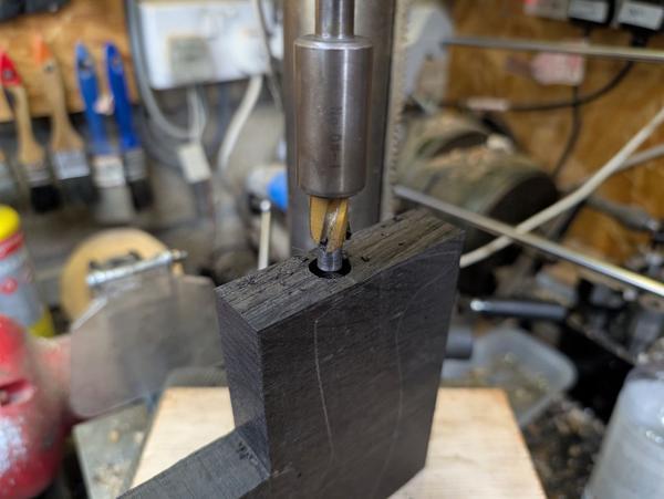
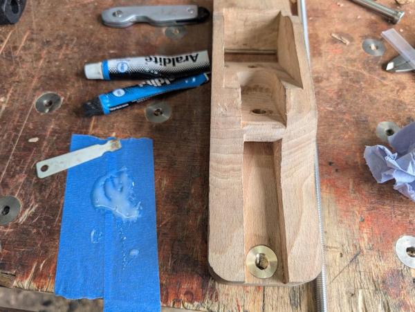
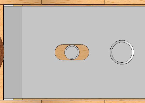
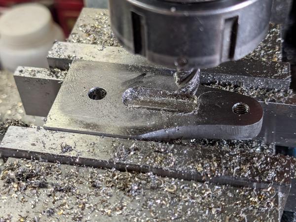
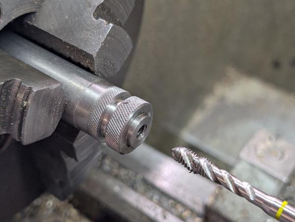
The one on the left is 9 mm through with a 14 mm flat surface added with an end mill (the flat surface gives the nut that the lever cap will act against something to press against). The right-hand hole was drilled 6.8 mm and tapped M8.

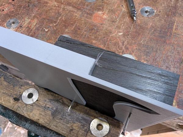
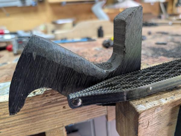
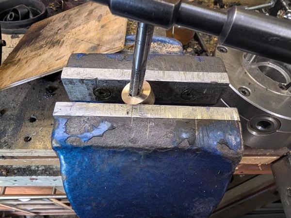
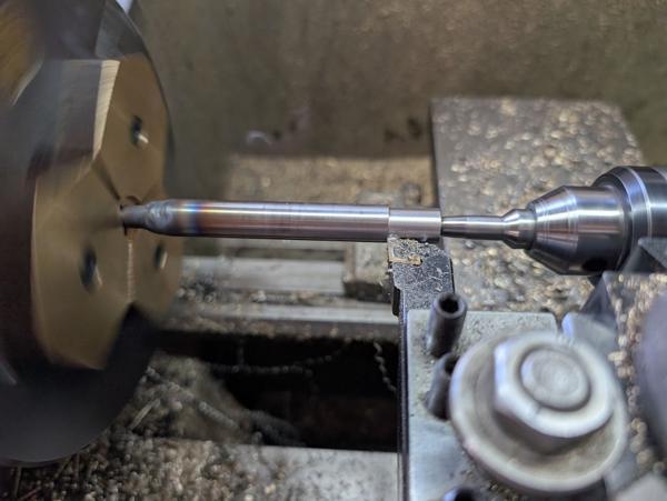
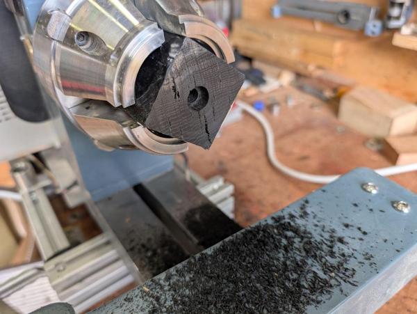
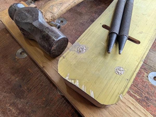
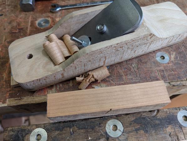
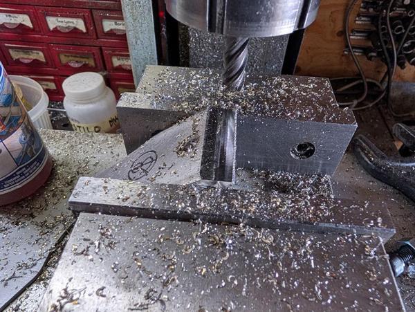
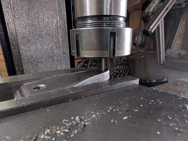
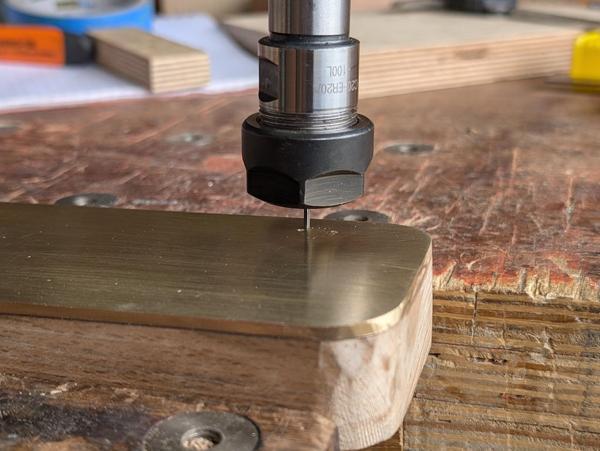
After resetting the lever cap at a steeper (but somewhat arbitrary) angle in the mill vice, I milled the tip down a bit to give some clearance for shavings:

2026-04-11-18-milled-tip_600.jpg


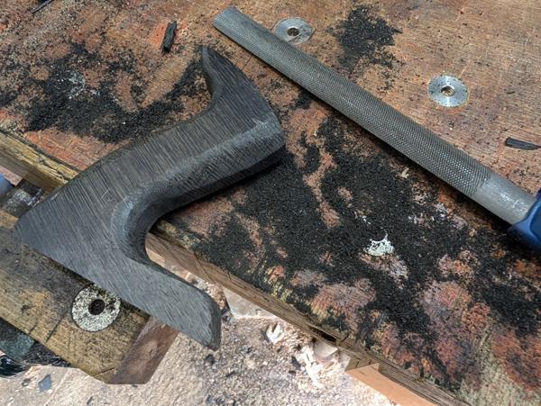
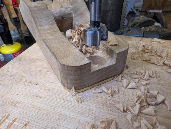
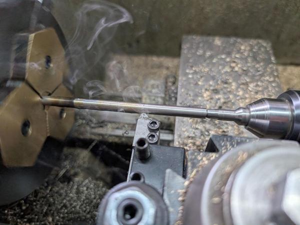
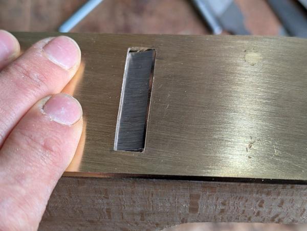
The 5° angle of the lever cap isn't quite enough to completely clear the cap iron's protruding nut, so I gave my little milling machine a slightly hard life and milled a pocket out of the back with a 12 mm carbide end mill:

2026-04-11-19-milled-pocket_600.jpg


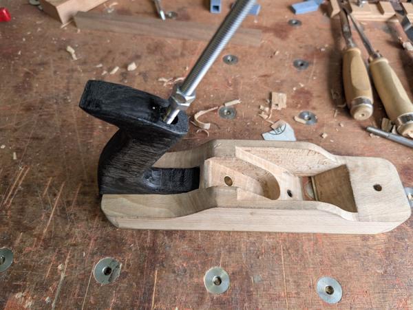
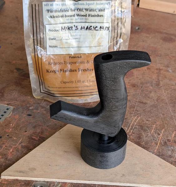
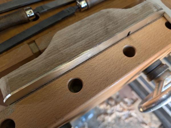
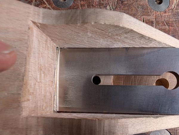
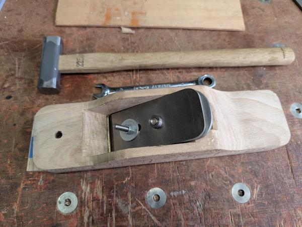
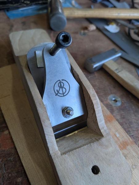
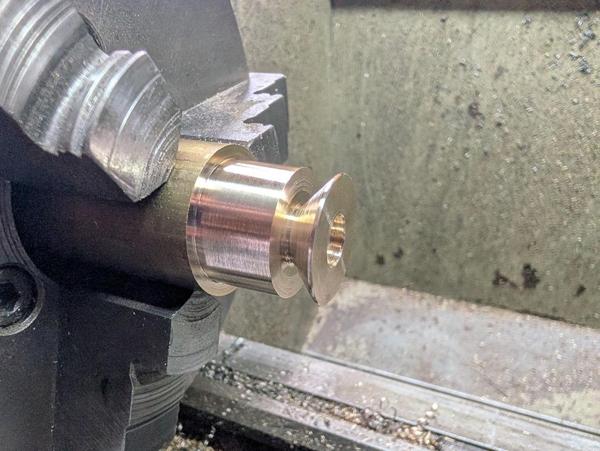
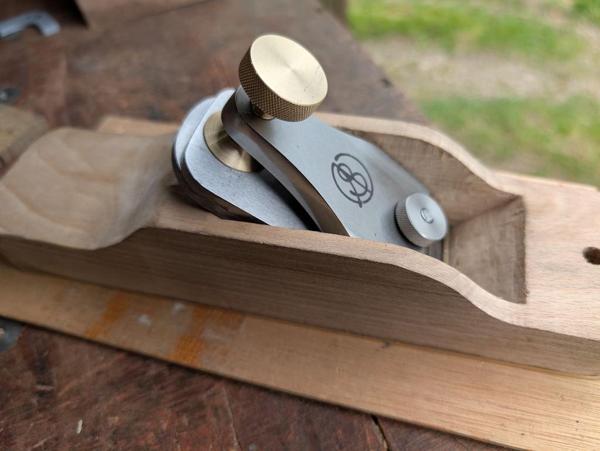
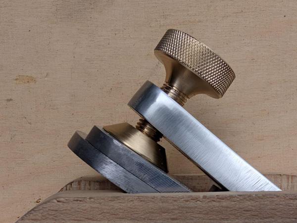
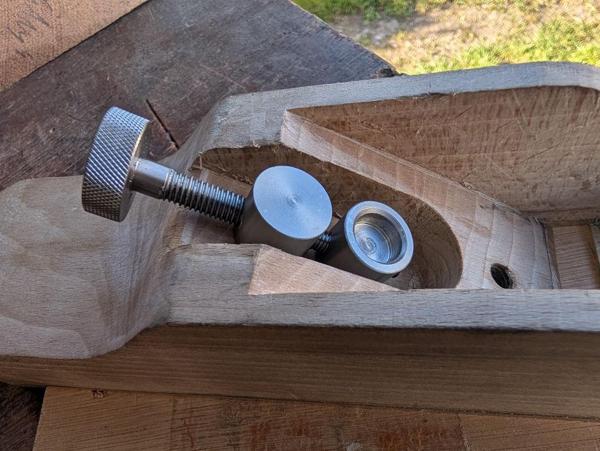
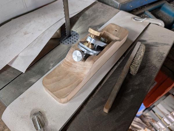
With that (and a bit of deburring) complete, the lever cap body is done and I could do a test fit using some standard hardware for now, along with an off-cut of aluminium sheet to protect the cap iron surface from the big M8 cap screw's tip:

2026-04-11-20-test-fit_600.jpg


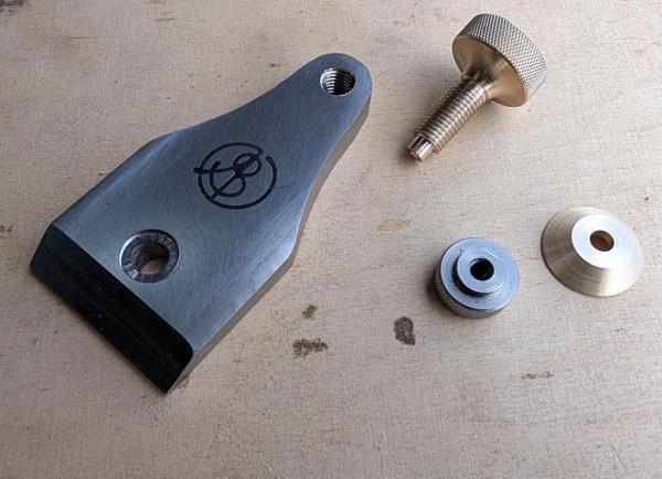
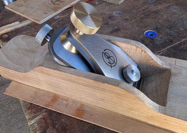
It seems to work well, applying plenty of force to hold the blade rigidly. Tomorrow I'll get started on some of the remaining metal hardware: the knurled nut to replace that M6 nut at the bottom of the lever cap, the brass knurled knob and pressure pad for the top of the lever cap and if time allows I'll also get started making the adjustment mechanism.
 
Impressive! Your engineering experience is paying off big time.
 
.....You probably already know this and have a plan in mind, but brass soled planes are unusual. The reason is that the relatively soft brass can leave black marks on the wood being planed......

I had never seen a brass-soled plane until yesterday at Carlton Scroop, where one of the tool sellers had a couple of fantastic skew shooting planes made of brass. I didn't ask about them, but I imagine they were at least 50 or 60 years old.
 
This morning I've been making the hardware to go with the lever cap, but first I decided I wanted a larger thread for the clamping screw. I put an M8 screw in the mill's collet chuck and screwed the lever cap onto it and that allowed me to put it in the vice in such a way that the hole was aligned with the spindle:

2026-04-12-01-aligning-lever-cap_600.jpg


After drilling it out 8.8 mm, I took it over to the bench vice and tapped M10 × 1.25.

2026-04-12-02-tapping-again_600.jpg


I probably would have gone with M12 × 1.25 if I had the tap, but my collection "only" included M12 × 1, M12 × 1.5 and M12 × 1.75! I'm sure either of the finer pitch ones would have been okay, but the 1.25 mm pitch just seemed about right for this application.

Next up was a very simple knurled nut for the pivot screw:

2026-04-12-03-simple-nut_600.jpg


That can be quite small as it is never properly tightened, just snugged lightly up against the lever cap before tightening the clamping screw.

I wanted a clamping arrangement a bit like the one on my Veritas low-angle smoothing plane. That has a large foot that presses down on the blade (there's no cap iron on the Veritas), spreading the force. I started by making the foot out of a bit of 32 mm brass, turning it down to 26 mm and then putting a 45° taper on it. It got drilled through 6 mm and counterbored 12 mm:

2026-04-12-04-turning-foot_600.jpg


After parting off, it went in the home-made soft jaws for facing to length:

2026-04-12-05-facing-in-soft-jaws_600.jpg


The clamping screw itself was made out of the same bar of brass. I used a tool with a big radius on it to reduce the diameter:

2026-04-12-06-turning-knob_600.jpg


It didn't need a radius like that, I just did it because I felt like it.

The bigger section got knurled, the smaller section threaded M10 × 1.25 and the tip reduced and lightly spot drilled:

2026-04-12-07-knurled-and-threaded_600.jpg


All of the above gave me this kit of parts:

2026-04-12-08-all-the-bits_600.jpg


On the Veritas lever cap, the foot is held in place with a circlip:

2026-04-12-09-veritas-foot_600.jpg


That is a very sensible option for a mass-produced part, but I'm only making one and I didn't have any circlips small enough. Instead, I assembled it all and used a punch to mangle the brass tip a bit so it couldn't go back through the hole:

2026-04-12-10-mangled-foot_600.jpg


Unfortunately, I was a bit too aggressive with the mangling and it ended up a bit tighter than I would have liked: it would rotate but not very easily. There was a bit of excess screw thread so I decided to just have another go. To that end, I put the assembly in a collet block in the mill vice and milled out the end of the screw:

2026-04-12-11-have-another-go_600.jpg


It could then go in the soft jaws on the lathe for a new tip:

2026-04-12-12-soft-jaws-again_600.jpg


This time I was a bit more cautious and hit it just enough that it wouldn't come back out:

2026-04-12-13-just-enough-to-stop-it-coming-out_600.jpg


With that done (and the custom dual-thread threaded bar I made a few posts ago shortened slightly), I could do a trial assembly:

2026-04-12-14-test-fit_600.jpg


I'm really pleased with how that came out: it assembles easily and holds rigidly.

I mentioned early on that I was drilling the holes through the lever cap at an angle to account for its tilt. I think this photo shows what I was aiming for quite well:

2026-04-12-15-showing-angles_600.jpg
 
This afternoon I've made the rest of the metal hardware. I started with an extremely simple bit of brass turning, to make this little cylinder:

2026-04-12-16-simple-brass-bush_600.jpg


That goes in this hole and gives a smooth rotating surface for part of the adjuster mechanism to spin in:

2026-04-12-17-dropped-into-place_600.jpg


Next up were three steel pieces. I didn't take any photos of the process, but you can imagine it if you read some earlier posts and look at the photos of stuff being turned in the metal lathe!

2026-04-12-18-three-steel-parts_600.jpg


The bottom two are 20 mm diameter 303 stainless steel, the top one is 24 mm diameter (at its widest point) mild steel (EN1A). I would have made the screw out of stainless steel as well but I didn't have any big enough and I wasn't confident I'd got the lengths right anyway. I might make a new one out of stainless at some point if I can be bothered (or if that one rusts!).

This is how they fit together and in the plane:

2026-04-12-19-steel-parts-fitted_600.jpg


The upper thread is M8 × 1.25 mm. The lower thread is M6 × 1 mm left-hand. The two together work as a differential thread: when you rotate the screw through 360°, the screw moves down through the upper fixed part by 1.25 mm. At the same time, the lower moving part moves up along the screw by 1 mm. The net result is that one turn of the screw moves the lower piece by 0.25 mm. The head of the screw that holds the blade to the cap iron sits in the pocket in the lower moving part and hence gets moved with the movement of the lower piece.

Shoving the knob side-to-side rotates it around the upper fixed part and hence causes the lower moving part to shove the blade side-to-side.

The last job for today was to fit everything and see how it looks:

2026-04-12-20-all-hardware-fitted_600.jpg


The adjuster seems to work well (better than I expected if I'm honest). I found it quite straightforward to adjust the angle of the blade to get an even protrusion and it could be moved smoothly back and forth by turning the knob, before tightening the lever cap to hold everything firmly in place.

The next big job is to make a rear handle and a front knob for it, but that'll have to wait until next weekend now.
 
Oooooh....shiny!

That looks gorgeous, Al. That's very fine adjustment control, I reckon, if it's 1/4 of a mm per revolution.
 
Over the course of the week I've been mulling on the rather shabby job I'd done of hiding the screws from sight. For example, this was the photo I took of the front two screws:

2026-04-06-08-not-great_600.jpg


It's not great and I think I'll forever be wishing I'd done a better job of it if I don't do something about it now. To that end, I assembled some tiny little things:

2026-04-17-01-tiny-things_600.jpg


The brass pins (of which I have a pack) have a very slight taper to them, with 1.4 mm at the narrow end and (if memory serves me correctly) 1.7 mm at the wider end. The steel tool is a tapered broach.

This shows a rather extreme close-up of one of the screw areas at the front of the plane after I'd drilled a 1.4 mm hole where there was one of the blemishes:

2026-04-17-02-first-hole_600.jpg


I drilled quite a lot of holes (and I later went back and drilled a couple more):

2026-04-17-03-lots-of-holes_600.jpg


After drilling 1.4 mm, the taper broach got held in an ER20 collet chuck and turned by hand until it went fairly deep:

2026-04-17-04-taper-broach_600.jpg


The next photo shows three of the following stages:

2026-04-17-05-three-stages_600.jpg


First, a tapered pin is tapped firmly into the hole in the brass. Then the side cutters are used to trim it shorter. A few more taps from the hammer rounds over the top and then a file takes most of the waste away.

The plane then went back to the bandsaw table for more sanding (with the blade and lever cap in so that I was sanding it flat with any lever cap induced tension that would be present when planing):

2026-04-17-06-back-to-sanding_600.jpg


That process took most of the morning. The actual drilling, broaching, pinning, cutting and filing of the brass pins was less than an hour; the rest was sanding (partly to get rid of the ends of the pins but also to get it flat now that the lever cap's installed).

This shows that same first hole (albeit at a slightly less extreme zoom level) that I showed earlier in this post:

2026-04-17-07-much-better_600.jpg


As a reminder, this is what the whole of the bottom looked like before today's efforts:

2026-04-06-07-that-will-do-for-now_600.jpg


This is what it looks like now:

2026-04-17-08-whole-base_600.jpg


I'm much happier with it now. There are still some imperfections if you look really closely, but you really have to be looking for them to spot them.
 
Some people might think that was unnecessary but if you approach each project as an opportunity to improve your results - as I believe you do - the result justifies the effort.
 
With the metalwork all done, it was time to get back to the difficult stuff: woodwork.

A couple of weeks ago, I received a package from a very generous member of this parish (thanks @Mike G). In the parcel were these two bits of bog oak (home-made plane for scale 😉)

2026-04-17-11-bog-oak-pieces_600.jpg


All being well, these pieces will become the handle and front knob of the plane. I've never tried making anything even remotely like a plane handle before, so I thought I'd make sure I stood the best chance of having two goes at it by cutting the bog oak piece in half like this...

2026-04-17-12-ryoba_600.jpg


... and like this:

2026-04-17-13-fret-saw_600.jpg


A coping saw would have been much better than a fret saw for the job, but my coping saw needs a new blade (and it's not a very good coping saw anyway, being a cheap modern one from a DIY store).

It will probably surprise no-one that I'd 3D-printed a couple of things:

2026-04-17-14-template-and-test-piece_600.jpg


On the right is a test handle of approximately the shape I'm aiming for. I printed that so that I could hold it in my hand and see how it felt. On the left is a template for marking the shape onto the bog oak piece (with a couple of panel pins holding it in place and also marking the centres for the inside curves). The template also has a dog-leg on the top that's used to mark the location of a through hole for a screw:

2026-04-17-15-drill-hole_600.jpg


That through hole got drilled on the pillar drill, starting with an 8 mm spur bit...

2026-04-17-16-drilling_600.jpg


... and finishing with a long-series metalworking bit:

2026-04-17-17-long-drill-bit_600.jpg


It came out of the bottom very slightly off-centre, but given the depth of the hole I was quite happy with it. The top got opened up with a counterbore (which may have to be deepened later but it's easier to at least get it started while the block has some flat edges):

2026-04-17-18-counterbore_600.jpg


Two Forstner bits (30 mm and 32 mm) were used for the inside curves:

2026-04-17-19-forstner_600.jpg


The bandsaw got rid of the bulk of the rest of the waste:

2026-04-17-20-bandsaw_600.jpg


The base of the handle got planed flat (you can see the slight offset in the drilled hole here):

2026-04-17-21-planing-base_600.jpg


Incidentally, I haven't actually figured out how the handle is going to be secured in place. It'll go into a mortice in the plane body and be glued and there will be a screw of some form (probably an M8 low-head machine screw) going down through the handle. However it doesn't really have anything to "bite" into in the plane body and if I just drill a hole (e.g. for a threaded insert) into the plane body, the hole (or the threaded insert) is very likely to pop out the back of the plane.

I've got a few ideas for how to deal with that, but I think it'll be easiest to worry about it when I get there.

Next up, I used a Shinto rasp to bring the overall shape down to the pencil line (while keeping the edge square for now):

2026-04-17-22-shinto_600.jpg


The rasp then did most of the rounding over:

2026-04-17-23-more-shinto_600.jpg


I then switched to a half-round file as it could get into the inside curves and round them over:

2026-04-17-24-filing_600.jpg


There was a crack that I hadn't managed to completely cut off when chopping up the bog oak piece:

2026-04-17-25-crack_600.jpg


Hopefully some thin superglue will sort that out:

2026-04-17-26-superglue_600.jpg


Next up was lots of card scraping to refine the shape and clean up the round-overs a bit:

2026-04-17-27-card-scraping_600.jpg


I haven't finished refining and smoothing by any means, but I think it's close enough now (it feels comfortable in the hand) to start working on the mortice in the plane body. That's something I'm feeling a bit daunted by (as there's a lot of work that's gone into the plane body and I don't want to mess it up) so I decided to leave that until tomorrow.
 
Back
Top