• Hi all and welcome to TheWoodHaven2 brought into the 21st Century, kicking and screaming! We all have Alasdair to thank for the vast bulk of the heavy lifting to get us here, no more so than me because he's taken away a huge burden of responsibility from my shoulders and brought us to this new shiny home, with all your previous content (hopefully) still intact! Please peruse and feed back. There is still plenty to do, like changing the colour scheme, adding the banner graphic, tweaking the odd setting here and there so I have added a new thread in the 'Technical Issues, Bugs and Feature Requests' forum for you to add any issues you find, any missing settings or just anything you'd like to see added/removed from the feature set that Xenforo offers. We will get to everything over the coming weeks so please be patient, but add anything at all to the thread I mention above and we promise to get to them over the next few days/weeks/months. In the meantime, please enjoy!

Chairs - Done!

And this is just the mock up/proof of concept. You have to do this 6 more times in oak. I am in awe of the discipline and patience required to do this, the repetition would, I am sure, drive me insane . From what I can see you have all the attributes required not to need luck to complete this.
I'm not too phased by the repetition. I didn't really enjoy making the laminations for my table leg as that was almost entirely pushing wood through machines for hours on end. All of the components in the chair are quite interesting shapes, so I think I'll enjoy making them.
 
Re: clamping curved surfaces: you could also try making clamping blocks with a complementary curve against the leg but a square face to the clamp.

I'm with you on trying a new project out on scraps before the real thing.
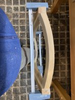
Gary, that thought has occurred to me too. I think I'll have a go at making some and see how it goes. The benefit would be that it's probably easier to shape the leg when it's not attached to the front rail. I think the only potential issues are whether the curved cauls could slip off (although a lip onto the flat face of the leg should address that), and whether my curves in the legs are consistent enough to fit the cauls!
 
Gary, that thought has occurred to me too. I think I'll have a go at making some and see how it goes. The benefit would be that it's probably easier to shape the leg when it's not attached to the front rail. I think the only potential issues are whether the curved cauls could slip off (although a lip onto the flat face of the leg should address that), and whether my curves in the legs are consistent enough to fit the cauls!
Hot melt glue holds clamping blocks well enough to take clamping forces, and cleans off nicely.
 
Yesterday and today I had a crack at making the side rails.

The front end of the side rail is not too bad but still has a compound angle. The long shoulder is angled to account for the rake/slope of the seat:
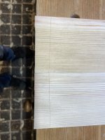
IMG_3605.jpeg

The edge shoulders are angled to account for the seat taper (i.e. the seat gets narrower towards the back of the chair):
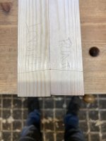
IMG_3603.jpeg

The tenon is angled (in that it will be at 90 degrees to the shoulders), but not all that severely so I'm not worried about short grain.

Although it's relatively simple, it still took me a long time to work it all out and get the tenon in the right place. Thinking about my exchange with Mike on whether to use templates for the joinery, I decided that it would save stacks of time (and hopefully stupid mistakes) so I made a more accurate plywood template:
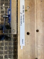
IMG_3607.jpeg

I subsequently made one for the face of the side rails too (no photo).

If the front end was hard enough, the back was a lot harder because there is a third angle to consider. That angle takes account of the tilt of the back legs. It's not all that easy to photograph, but this is what I ended up with:
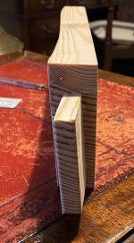
IMG_3613.jpeg

I was pretty happy with the fit in the exposed side of the mortise. Let's hope the real things are OK too!
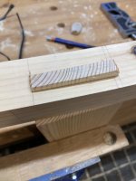
IMG_3608.jpeg

That exposed end grain on the side rail needs addressing. This results from the rear legs being tilted over. To get rid of that, I need to plane some twist into the side rail. That would be easy enough, but the side rail also has a bit of a serpentine curve in it. I didn't take proper photos of the layout, but I basically took my curve template and lined it up with the start and end points on both the top and the bottom of the side rail - i.e. the curve on the bottom ends where the rear leg crosses the side rail. On the top, the curve just ends at the corner of the side rail which is flush with the rear leg. However, the curves on top and bottom finish in the same place at the front of the side rail.

I suppose I could tilt my bandsaw table over and cut out most of the waste, but given the face ends up twisted, the angle of the bandsaw would need to change as I go along. I don't have a shipwright's bandsaw like Leo of Tally Ho fame (although he isn't using his at the moment....) which could do that, so I had to do it by hand. That might sound like a big job, but it actually went quite quickly. I had a fairly acceptable outcome after around 25 minutes.

I started by removing most of the waste by taking heavy cuts across the grain with a round bottom moulding plane:
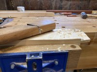
IMG_3612.jpeg

You can see the line I'm working too. I just needed to be careful (a) not to blow out the top edge (a fair chunk of the bottom will get cut off later so I was less worried about that); and (b) to remember that the line was different on the top and bottom edges. I went as close to the line as I dared with the moulding plane, and then switched to a spokeshave. I was checking that the face was flat from top to bottom as I went (by working to the lines, there is a tendency to leave a bulge in the middle).

This is the finished face.
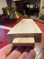
IMG_3614.jpeg

It's hard to photograph the twist, but you can see it better with two rulers as makeshift winding sticks:
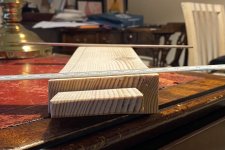
IMG_3617.jpeg

This is it with the front and rear legs attached:
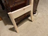
IMG_3618.jpeg

I've marked another curve on the bottom of the side rail, but didn't have time to cut that.

There's also a very small step from the front leg down to the side rail. That's there so that I can shave down the front leg so that the slope of the seat continues into the front leg.

Progress is going to slow down as I'm starting a temporary job on Tuesdays, Wednesdays and Thursdays for the next couple of months. That will however help pay for the timber!
 

Attachments

  • IMG_3613.jpeg
    IMG_3613.jpeg
    229.7 KB · Views: 0
  • IMG_3604.jpeg
    IMG_3604.jpeg
    154.9 KB · Views: 0
Oh, and I couldn't resist putting the whole thing together:

IMG_3611.jpeg

The back legs look chunky but they will be tapered and the upper part will also have a twist in them to match the curve of the crest rail. Fitting the crest rail and making and fitting the back bars are probably going to be the biggest challenge on this but that's a problem for the future...
 
That now defunct magazine dropped on my doormat last week!

Pete
It disappeared off the newsstands some years ago. I thought it gone altogether but it must have continued as a subscription only publication. I took it for many years but gave it up because it was getting too repetitive (for me anyway)
Brian
 
There’s a lot of subtle slopes curves and angles on that test chair Nick, it’s a shame we can’t all see it in the flesh, I think it’s something you have to be able to ponder and walk around- so that’s over to you.
 
Wow, you've got your work cut out for you, Nick. It looks great.
 
I've done a bit more on the practice chair.

Having finished the rear leg joints, I decided it was safe to taper the legs. My original plan was to take the taper off the inside and outside faces. The second plan was to do the upper taper just on the inside, and the lower taper off both faces. In the end, I decided to do the taper on the upper and lower parts of the leg on the inside face only.

Here it is marked out:

IMG_3626.jpeg

IMG_3627.jpeg

Although the leg is curved, it was easy enough to do most of the cutting on the bandsaw before planing the final surfaces (no photos unfortunately).

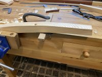
I then tackled the crest rail. I'm afraid I did this in a bit of a rush so didn't take many photos. However, the method was to make a template by marking the inner and outer arcs on a piece of ply using the trammel I made before bandsawing and spokeshaving to the lines. I used the template to mark the shape on the wood and then angled the table on my bandsaw to cut the rail. At this stage, I cleaned up the inside face of the rail only, in case I needed a bit of wriggle room.

I fitted the crest rail by scribing some approximate lines and then testing and adjusting until I was happy with the fit.

I joined the rail to the legs with a domino. The first attempt was a little bit off :oops::

IMG_3632.jpeg

I basically forgot to take account of the angles. My method did work in the end, but I might consider making some sort of jig to do this as the pieces are small making the job a bit precarious.

IMG_3629.jpeg

The photo above also shows how the legs will be shaped to follow the curve of the crest rail. As noted in a previous post, this will involve the front and back faces of the legs being twisted. I used the leg template to mark out the curve on the inside/outside edge, feathering it out at seat level. I then planed and spokeshaved to the lines.

These photos show the process underway and the lines I'm working to.

IMG_3630.jpeg

IMG_3631.jpeg

It seemed to work well and I like the look of it (ignore the small gap - this is not glued and is not under any clamping pressure):

IMG_3634.jpeg

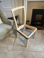
The overall shape of the chair is now complete and I like it.

IMG_3633.jpeg

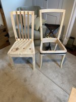
It's interesting to compare it with the rough prototype. It's not surprising, but the shaping I've done has had a big impact on the overall look.

IMG_3637.jpeg

The next job is to design, make and fit the back bars. That's easily going to be the hardest part.
 

Attachments

  • IMG_3629.jpeg
    IMG_3629.jpeg
    199.5 KB · Views: 4
That's looking great. And a real demonstration of why cheap mass-produced chairs look clunky. They leave out all your thoughtful shapes and angles!
 
I like that a great deal, I can see that the top of the back legs is angled to meet the crest but difficult to tell further down near the seat, just concerned that the square corners will dig into the sitters back.
Thanks. That has crossed my mind, but the shape near the seat was the same on prototype and that was OK. I don't think that making the curve at the top should affect that, but I'll add some sort of seat in the current version and will try it out.
 
Great work so far and the design is improving.

However.....when you (or I) go to a high end restaurant, it is worth thinking about what the best chairs are like. A really good chair for dining has to be comfortable for say three hours. It should not make you slouch, cause you to fidget or give you a numb bum or thighs. You should be thinking about the food and wine and what a great time you are having, and the chair should be taken for granted as super comfortable, warm and enclosing. In my book this always involves a cocoon style chair with a well padded back that wraps to some extent around the body. Much as I like classic designs aesthetically, for actual use as a comfortable dining chair they are never the best.

Upholstery is very important too, and makers rarely give this enough thought.

My gut feel, as my gut is close to the seat, is that function is massively more important than anything else. You never look at a chair once you are sat on it.
 
What is it about Nick's design, Adrian, which doesn't fit in with your picture of the ideal or which suggests you couldn't be comfortable on it for 3 hours? Is it just the lack of padding on the back?
 
Great work so far and the design is improving.

However.....when you (or I) go to a high end restaurant, it is worth thinking about what the best chairs are like. A really good chair for dining has to be comfortable for say three hours. It should not make you slouch, cause you to fidget or give you a numb bum or thighs. You should be thinking about the food and wine and what a great time you are having, and the chair should be taken for granted as super comfortable, warm and enclosing. In my book this always involves a cocoon style chair with a well padded back that wraps to some extent around the body. Much as I like classic designs aesthetically, for actual use as a comfortable dining chair they are never the best.

Upholstery is very important too, and makers rarely give this enough thought.

My gut feel, as my gut is close to the seat, is that function is massively more important than anything else. You never look at a chair once you are sat on it.
I don't disagree with this, but mine are slightly fancy kitchen chairs rather than dining chairs as such. We've had wooden chairs with drop in cushions in the kitchen for many years and have always found them comfortable for the way we use them. The prototype was also fine so I'm fairly confident they will be alright.
 
What is it about Nick's design, Adrian, which doesn't fit in with your picture of the ideal or which suggests you couldn't be comfortable on it for 3 hours? Is it just the lack of padding on the back?
It is customer feedback Mike from our little restaurant venture and discussion with a chef friend who lives nearby and who until recently ran a 2 star in a hotel in London. People much prefer a padded back and some degree of wrap around. They think it both looks and feels more luxurious. I have among others 8 modern padded chairs, 6 rosewood antique chairs (which are very well made but guests prefer others) and a Chippendale with arms. My own preference is the chippendale but if I had to sit for three hours, which people often do for the parties and corporate dinners we put on, then my choice would be a fully padded chair with part wrap around. We have just bought in fact another 2.5 metre table (I don't have time to make another one) and fully padded chairs and I discussed it a lot. Chairs are beech framed and robust.

As woodworkers we like making stuff and enjoy the quality of fine craftsmanship. Chair users don't care about that mostly - they want comfort. In a dining establishment customers usually choose a fully padded banquette or wrap around over a traditional chair. That tells me something. Women always choose the comfort option.
 
Last edited:
I've done a bit more on the practice chair.

Having finished the rear leg joints, I decided it was safe to taper the legs. My original plan was to take the taper off the inside and outside faces. The second plan was to do the upper taper just on the inside, and the lower taper off both faces. In the end, I decided to do the taper on the upper and lower parts of the leg on the inside face only.

Here it is marked out:

View attachment 31975

View attachment 31976

Although the leg is curved, it was easy enough to do most of the cutting on the bandsaw before planing the final surfaces (no photos unfortunately).

I then tackled the crest rail. I'm afraid I did this in a bit of a rush so didn't take many photos. However, the method was to make a template by marking the inner and outer arcs on a piece of ply using the trammel I made before bandsawing and spokeshaving to the lines. I used the template to mark the shape on the wood and then angled the table on my bandsaw to cut the rail. At this stage, I cleaned up the inside face of the rail only, in case I needed a bit of wriggle room.

I fitted the crest rail by scribing some approximate lines and then testing and adjusting until I was happy with the fit.

I joined the rail to the legs with a domino. The first attempt was a little bit off :oops::

View attachment 31981

I basically forgot to take account of the angles. My method did work in the end, but I might consider making some sort of jig to do this as the pieces are small making the job a bit precarious.

View attachment 31982

The photo above also shows how the legs will be shaped to follow the curve of the crest rail. As noted in a previous post, this will involve the front and back faces of the legs being twisted. I used the leg template to mark out the curve on the inside/outside edge, feathering it out at seat level. I then planed and spokeshaved to the lines.

These photos show the process underway and the lines I'm working to.

View attachment 31978

View attachment 31979

It seemed to work well and I like the look of it (ignore the small gap - this is not glued and is not under any clamping pressure):

View attachment 31980

The overall shape of the chair is now complete and I like it.

View attachment 31983

It's interesting to compare it with the rough prototype. It's not surprising, but the shaping I've done has had a big impact on the overall look.

View attachment 31984

The next job is to design, make and fit the back bars. That's easily going to be the hardest part.
I do like the look of that chair. Very smart and a lot of skill going into making it.
 
Tipping back on chairs...
Does anyone else recognise the term "kiddling"?
I can't remember the number of time we were chastised as children for kiddling on the chairs.
"Stop kiddling!"
I've yet to find anyone else who recognises the word.
S
Has anyone ever met someone who fell off the back of a chair and broke their neck? 🤔🤣
 
Has anyone ever met someone who fell off the back of a chair and broke their neck? 🤔🤣
No. But a former neighbour of mine, our local bank manager back in the day, fell off the back of his office swivel rocker and cracked his head on the table behind resulting in permanent brain damage.
 
I'm still putting off how to do the back slats (although I do have a few ideas which I need to get around to trying)!

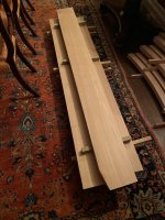
However, I have started getting the components out of the boards. My plan is to get them close to final size, leaving around 2mm on the width and thickness. I'll then bring them indoors so they have some time to acclimatise.

It was very heavy work. The boars are about 5m long and around 54mm thick so they're very hard to move by myself. I could just about flip them over so that I could identify knots and other defects.

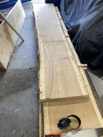
My strategy was to mark out the components so that I could do crosscuts which my small, battery powered, circular saw is happiest with. The resulting chunks were just about manageable on the bandsaw.

Laying out the rear legs:

IMG_3648.jpeg

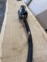
If I had to do a cut with the grain (which I did when laying out the pieces for a worktop I'm making for my parents in-law and which is also coming out of this timber), I employed some wedges to stop the blade getting clamped.

IMG_3657.jpeg

The key factors in choosing how to get the parts out of the wood were:
  1. Trying to use "rift sawn" wood for the legs and quarter-sawn for the rails.
  2. Avoiding sapwood and pith.
  3. Avoiding knots and other defects (although there weren't too many of these).
  4. Trying to use the wood as efficiently as possible.
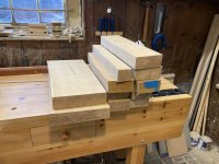
This is the pile I've got:


IMG_3656.jpeg

Rear legs, front rails, side rails, rear rails and front legs.

IMG_3649.jpeg

These are the pieces for the front legs where you can see the diagonal, rift-sawn, end grain.

I've since started sizing the components. I used the P/T to clean up a face, but then hand planed it to remove any minor twists or bow (which I sometimes get from my PT). I used the P/T to roughly square up and edge and again perfected it with a hand plane. The other face and edge will be left machined (either off the table saw or thicknesser) for now until I bring the components down to their final size.

I never get bored of quarter-sawn oak:

IMG_3658.jpeg
 
I remember this stage well, from my ash bed build. That was good thick boards, which needed lots of careful planning before cutting, but not on the scale of your chairs project. YouTube videos never show how long all this takes or how heavy those boards can be.
Do you have a decent sized space where you can spread out, or must you keep moving and re-stacking?
 
I remember this stage well, from my ash bed build. That was good thick boards, which needed lots of careful planning before cutting, but not on the scale of your chairs project. YouTube videos never show how long all this takes or how heavy those boards can be.
Do you have a decent sized space where you can spread out, or must you keep moving and re-stacking?
I couldn't spread them out really so it was a case of working down the stack.

It's a proper workout! It's nice that I'm working with smaller pieces now.
 
I've finished roughing out the components (aside from the crest rails, which I need to have a think about, and the back bars which will be laminated).

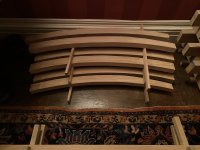
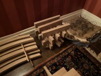
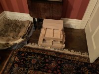
So this is where the parts are at the moment (all in our dining room acclimatising).

IMG_3659.jpeg

12 rear legs. You can see that I've very roughly cut the shape. I've left about 5mm over all round. I can see that cutting the curves could lead to some movement and I hope I've left enough to still get the right shape out of the blank after any movement has happened.

IMG_3660.jpeg

12 side rails (alongside my wife's current upholstery project!).

IMG_3661.jpeg

6 rear rails, 6 front rails and 12 front legs.

IMG_3662.jpeg

5 boards which will be a top for some units in my in-laws new kitchen.

I don't think I've got any excuse not to think about the back bars now, but I'm working a bit this week so I may not have much to report for a while.
 
I've started thinking in detail about the back bars for my chair and it's tricky to say the least. I'm wondering if anyone has any thoughts. If you can be bothered to read what follows and give me the benefit of your wisdom, then that would be greatly appreciated. Don't worry if not though, because just writing it down has been a helpful process!

The basic plan is as follows:
  • 6 bars
  • Each bar is 25mm wide and 8mm or 10mm thick (I'm thinking of using a domino to cut the mortises)
  • They'll be laminated to create the necessary bend
  • Ideally they should be evenly spaced where they hit the rear seat rail and also where they hit the underside of the crest rail
It's the fourth point above that I'm grappling with.

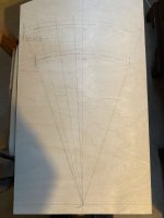
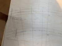
These drawings are a plan view of the chair.

IMG_3666.jpeg

IMG_3667.jpeg

The top set of arcs represents the crest rail, and the bottom set the seat rail. I designed the chair so that these arcs are co-centric (you can see they have a common centre). I did that because my instinct was that it might be helpful when doing the back bars!

The hatched sections on each arc represent the back bars and these are evenly spaced on the seat rail/crest rail.

If I draw lines from the arc centre through the centre of the back bar locations, you can see that the seat rail positions are not quite 'in line' with the crest rail positions. I think this is a consequence of the angle of the two arcs being different (principally because the legs tilt outwards making the crest rail 'wider' than the seat rail). To be honest, I think it's a bit of a fluke that the locations of the bars are so close.

Without redesigning the rest of the chair (which I'm not considering as an option at the moment!), to achieve the right spacing of the bars top and bottom, I believe I would need to tilt each bar slightly 'outwards'. The amount of tilt gets greater as the bars move away from the centre. Am I right?

Assuming I'm right, I could tilt them in that way and would then need to have slightly angled shoulders and slightly angled mortises to get a good, gap-free, fit. The angle would change from bar to bar. Another possible consequence of tilting the bars which I can't really visualise, is that I think it would be necessary to introduce a slight twist into the bar in order to be able to keep the mortises tangent to the centre arc of the seat rail/crest rail. I don't know if that would be enough of a twist that I would have to build it in as part of the lamination process (that sounds hard!), or whether I could wrestle the bars into the position? Agreed? Any thoughts?

Another solution would be to abandon the even spacing of the bars. As you can, the amount of adjustment is quite small. The outer bar (which is most 'off') is about 2.5mm out at the crest rail and about 2mm out at the seat rail. What I'm wondering is whether I could split the difference on each rail - i.e. for the outer bar, I'd move it 'inwards' at the crest rail by 1.25mm, and outwards at the seat rail by 1mm. My hope is that the bars are then square at the top and the bottom without creating glaringly uneven spacing. Sound right?

If anyone has any other thoughts, I'd love to hear them. In particular, is my 2D representation capturing the problem here or am I missing something fundamental?

Lastly, don't worry too much at this stage thinking about the bend in the bars. I'm thinking about that and will probably have to do another post on that!!

If you've managed to read this far, thank you!
 
I read it all through, Nick, twice, and I think I've now got a grip on the issue. One of the problems I think is use of terms such as "square", which has got me puzzled when we're talking about curved bits of wood meeting with curved bits of wood.

Imagine flattening out your crest rail and your seat rail. These are different lengths. Dividing up both rails such that the gaps between the back "bars" is even is necessarily going to force the shoulders of the tenons out of square. One solution might be to not have shoulders, and to just have bare-faced joints (ie set the entirety of the "bars" into a mortice, as I think Andy T did this with his bed).

I wonder if you are trying to be a bit too "engineering" about it. Perhaps it comes with the territory of CAD modeling in 3D. It looks to me like your original pencil drawings dealt with the geometry of the back rest perfectly well, as did your maquette. It's perfectly possible to just do a take-off from your model and not try and insert a drawing between the model and the real-thing. I also wonder whether a boat-building approach might serve you better than doing millimetre-perfect laminations: make the back pieces roughly right out of solid timber, and then fair them in in situ. You could even make a cardboard or ply template for each of 3 or 4 locations up the back of the chair, giving you a clue as to how close you are to ideal as you shape the bars. The thing is, I think you're in "offer-up-and-adjust" territory with these pieces........classic hand-tool working technique...........and that doesn't sit well with the absolute accuracy of CAD modeling.
 
I agree with Mike, I think it will be a case of fitting each bar to its location on each seat. In theory each bar gets longer as you move from the middle bar to the edge because of the slope.
I would leave it a joinery problem rather than an engineering/drawing problem
Another choice that might make fitting easier is if the mortices were small say the thickness of the bar rather than width. It would mean the mortice and tenons were less strong but the shoulders could hide any wiggle room in the fitting.
 
I read it all through, Nick, twice, and I think I've now got a grip on the issue. One of the problems I think is use of terms such as "square", which has got me puzzled when we're talking about curved bits of wood meeting with curved bits of wood.

Imagine flattening out your crest rail and your seat rail. These are different lengths. Dividing up both rails such that the gaps between the back "bars" is even is necessarily going to force the shoulders of the tenons out of square. One solution might be to not have shoulders, and to just have bare-faced joints (ie set the entirety of the "bars" into a mortice, as I think Andy T did this with his bed).

I wonder if you are trying to be a bit too "engineering" about it. Perhaps it comes with the territory of CAD modeling in 3D. It looks to me like your original pencil drawings dealt with the geometry of the back rest perfectly well, as did your maquette. It's perfectly possible to just do a take-off from your model and not try and insert a drawing between the model and the real-thing. I also wonder whether a boat-building approach might serve you better than doing millimetre-perfect laminations: make the back pieces roughly right out of solid timber, and then fair them in in situ. You could even make a cardboard or ply template for each of 3 or 4 locations up the back of the chair, giving you a clue as to how close you are to ideal as you shape the bars. The thing is, I think you're in "offer-up-and-adjust" territory with these pieces........classic hand-tool working technique...........and that doesn't sit well with the absolute accuracy of CAD modeling.
Thanks Mike. That's helpful.

I definitely take the point about this not being an engineering project! To be honest, the CAD helps me because I'm not great at visualising things. The same goes for drawing this aspect out. Without doing that, I struggle to visualise what I'm trying to do!

I think I'm going to try moving the centres of the mortises a bit. I'm glad that I've got the prototype to try this out on!

My plan is to have bare faced joints but with a small shoulder on the edges.

Getting everything to fit well is bound to require a good amount of testing and adjustIng.
 
Mike is right. If you look at very fine antique chairs with slatted backs, they often have a slight "splay". A couple of years ago I made a replacement chair for a heritage property and had to replicate this aspect and rather difficult having never done it before. I had to cut a slight slope on each tenon, starting oversized and work to the target. With lots to do you may be able to devise a repeatable method. Good luck.
 
.... In theory each bar gets longer as you move from the middle bar to the edge because of the slope.
I would leave it a joinery problem rather than an engineering/drawing problem.....
Indeed. Now, think of an illiterate and innumerate village joiner making this 150 years ago. I'm sure he would have managed perfectly well. The beauty of the "offer-up-and-adjust" method is that all of the work would happen at the under-edge of the crest rail. In other words, the splats would be dry fitted into the seat rail, and their top ends adjusted as necessary until the crest rail fitted. I'd have a little bet that rasps were the primary weaponry.
 
All good advice, not quite so sure about this idea.
How about fitting them at the correct spacing on the seat rail, then bring the crest rail to its ( as close as possible ) position against the splats possibly using G cramps to hold it all together, this will allow you to mark the “off square” shoulders onto the splats and also to mark the joints where the crest rail meets the back legs.
 
In theory each bar gets longer as you move from the middle bar to the edge because of the slope.
By having the crest and seat rails co-centric, I was actually hoping each bar could be identical, and think that would be the case if I didn't have to 'tilt' the bars outwards at all.

The spacing at the crest rail would be larger than at the seat rail, but that's not because of the slope. It's just a function of the crest rail being part of a larger circle. Like spokes on a wheel.

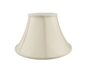
As I said, I find this hard to visualise. My analogy is to imagine the back of the chair as a section of an upside down lampshade like this:

IMG_3668.jpeg

That said, if I do end up tilting them, it's such a small amount that I think each bar could still have the same basic shape.

Whilst I agree this isn't an engineering project, I still need to decide where the mortises will be and be able draw and visualise what I'm making. If I can't do that then it will be hard to make!
 
All good advice, not quite so sure about this idea.
How about fitting them at the correct spacing on the seat rail, then bring the crest rail to its ( as close as possible ) position against the splats possibly using G cramps to hold it all together, this will allow you to mark the “off square” shoulders onto the splats and also to mark the joints where the crest rail meets the back legs.
If they're at the correct spacing on the seat rail and have "square" shoulders, then the spacing would be a bit off at the crest rail (as illustrated in my drawing). To get the spacing right at the top and bottom, I'd need to adjust the angle of the splats which is an adjustment to the shoulders top and bottom.

I think I'm going to try slightly adjusting the spacing top and bottom as it might make my life a lot easier. In fact, I don't think it will even be noticeable without measuring.
 
Years ago, I rescued bits of a Windsor chair from a skip. The seat and legs were complete but not the back, except for some thin back rails. They were bent (presumably by steaming) into a shallow s-curve. Cross section was a rounded off rectangle, about 22 x 15mm max. They were individually tapered in length and width, with no shoulders and would have fitted into a run of mortises at the back of the seat, laid out on an arc. Also into a similar arc of mortices under the back rail. I reckon all the adjustments were by spokeshaving these slats, being careful to keep opposite pairs symmetrical. I can't remember if the seat mortises were also curved at the ends. I'll check at the weekend.
This might have been the method that Mike's illiterate, innumerate joiner would have used.

You'll be wanting something more precise, I think.

I also think cutting shouders at both top and bottom would be impractical but might work at the bottom only, where they would be more visible.

(On my bed, I cut shoulders at top and bottom, which was possible because both sets were in a straight line and in the same vertical plane. Much simpler than an inverted lampshade.)
 
Thanks Andy. I did wonder about doing away with shoulders and having slightly tapered bare-faced and bare-edged tenons. Still not easy though...

I've picked up a few tricks for giving some scope for adjustment of the crest rail when getting shoulders to fit from some very helpful threads that Custard posted on UKW when he made Edward Barnsley style chairs.
 
That would be a much better source than my random ramblings!
 
Nick, I can’t remember if you have a CAD mode of the chair. If you do, would it be worth doing two models. One with even spacing at the bottom but square shoulders to see what it looks like overall. It could be compared to a second version with the non square shoulders and even spacing at the top and bottom. You could then decide if the look of being even at both ends is worth the complication.
 
Nick, I can’t remember if you have a CAD mode of the chair. If you do, would it be worth doing two models. One with even spacing at the bottom but square shoulders to see what it looks like overall. It could be compared to a second version with the non square shoulders and even spacing at the top and bottom. You could then decide if the look of being even at both ends is worth the complication.
It would definitely be worth doing that but I'm struggling to model the back bars! My design student and CAD expert son is unfortunately too busy to help me at the moment!
 
Back
Top