• Hi all and welcome to TheWoodHaven2 brought into the 21st Century, kicking and screaming! We all have Alasdair to thank for the vast bulk of the heavy lifting to get us here, no more so than me because he's taken away a huge burden of responsibility from my shoulders and brought us to this new shiny home, with all your previous content (hopefully) still intact! Please peruse and feed back. There is still plenty to do, like changing the colour scheme, adding the banner graphic, tweaking the odd setting here and there so I have added a new thread in the 'Technical Issues, Bugs and Feature Requests' forum for you to add any issues you find, any missing settings or just anything you'd like to see added/removed from the feature set that Xenforo offers. We will get to everything over the coming weeks so please be patient, but add anything at all to the thread I mention above and we promise to get to them over the next few days/weeks/months. In the meantime, please enjoy!

Clamp of Theseus

Dr.Al

Old Oak
Joined
Dec 31, 2020
Messages
3,561
Reaction score
2,242
Location
Dursley, Gloucestershire
Name
Al
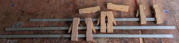
Earlier in the week, I came home to a large package, sent to me (apropos of nothing) from a very generous member of the MIG welding forum. He used to be a cabinetmaker but doesn't think he'll have a use for them any more and would rather they go to someone who would get some use out of them. This is what was in the package:

2026-03-14-01-three-free-clamps_600.jpg


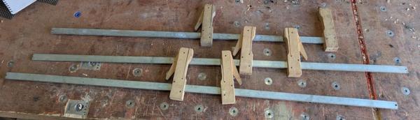
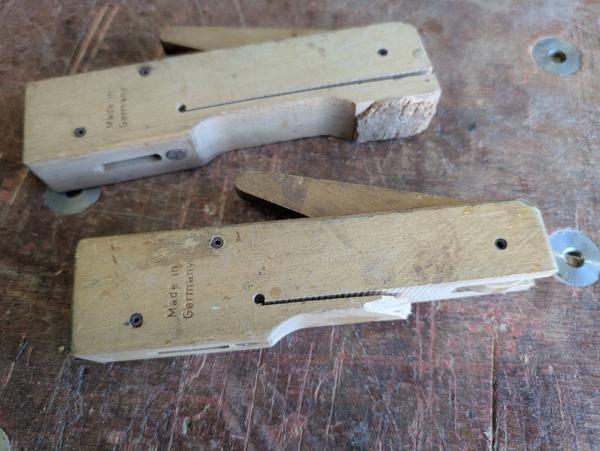
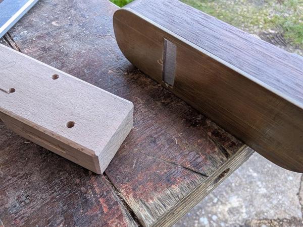
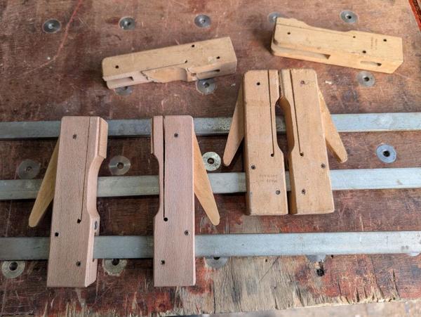
I have a few cam clamps from Klemmsia and they come in handy for some jobs. The ones I have are much shorter than these: I've never seen long bar versions of them. One of the clamps had a damaged head as you can see in this photo:

2026-03-14-02-broken-head_600.jpg


I'd been wavering a bit on what to do as my next project so that was an additional bonus on top of receiving free clamps in the post: I've got a little repair job to work on.

Only one of the clamp heads is broken but I decided that I'd try to replace the pair. The main reason for that is that I thought there was a fairly high chance I'd mess one of them up and in that case I'd have a spare. However, if all goes well I'll just replace the two heads so they match.

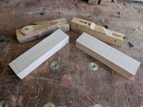
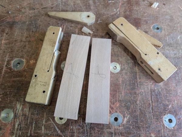
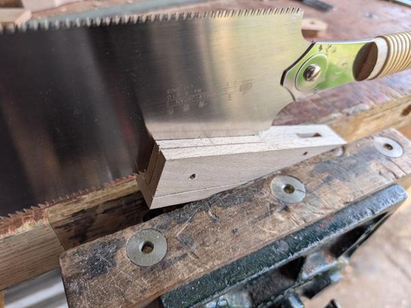
I started with these two bits of beech, bandsawn off a larger lump:

2026-03-14-03-two-bits-of-beech_600.jpg


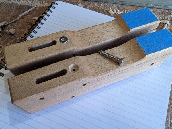
If you look closely at the photo, you'll notice that there's a diagonal line in the face of the broken clamp. That's from a hacksaw, which I used to cut a deeper slot in a slotted screw so that I could remove it (mainly to see how long it was). Given the head is broken, it didn't seem like a particularly big deal to cut into the face with the hacksaw and that made it much easier to cut the slot in the screw.

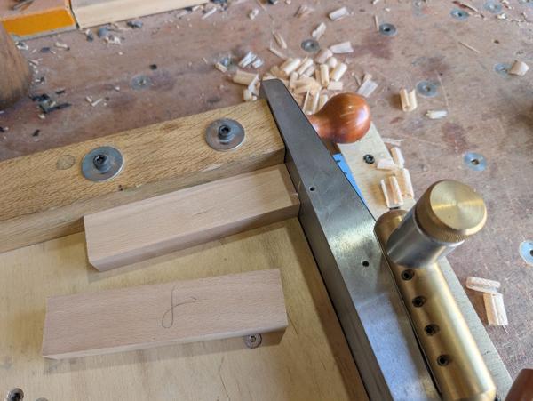
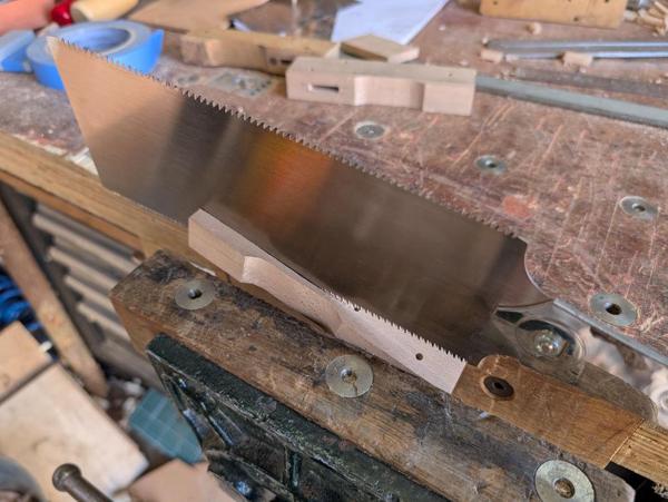
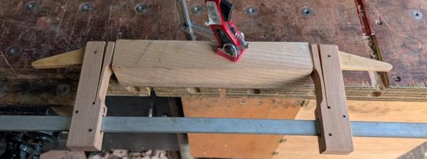
The next job was a lot of planing with the #4½...

2026-03-14-04-planing_600.jpg


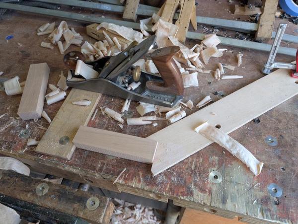
... and a bit of shooting with the low-angle jack:

2026-03-14-05-shooting_600.jpg


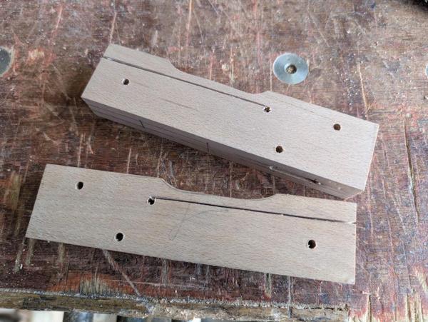
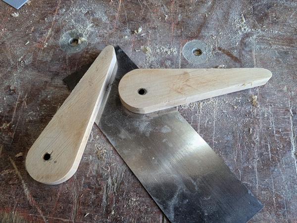
The beech pieces ready to be used:

2026-03-14-06-dismantled-head-and-beech-ready_600.jpg


The first thing I did was clamp the broken piece onto each of the beech blocks and use some transfer punches to transfer the positions of the roll pin holes and the relief hole at the bottom of the slit. I also drew round what was left of the body:

2026-03-14-07-transferring-marks_600.jpg


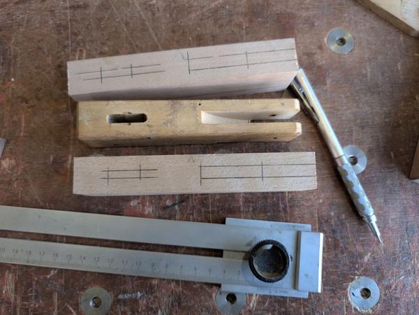
The pencil lines then got extended, using the whole clamp body for the curved line and an edge distance gauge for the straight one:

2026-03-14-08-pencil-lines-extended_600.jpg


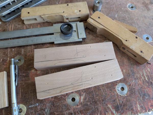
I also marked up the locations of the two mortices in each block:

2026-03-14-09-mortice-marks_600.jpg


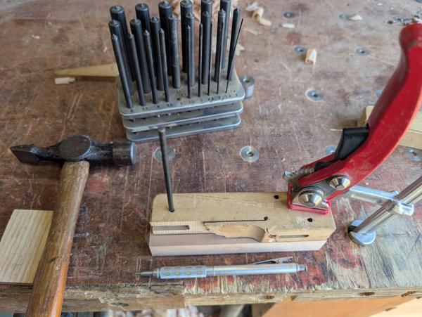
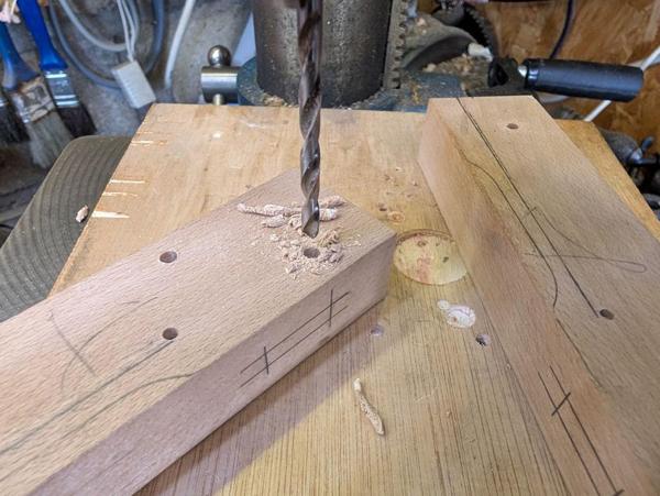
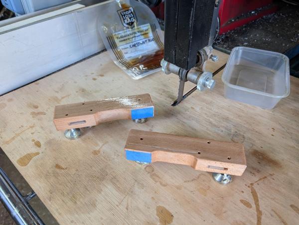
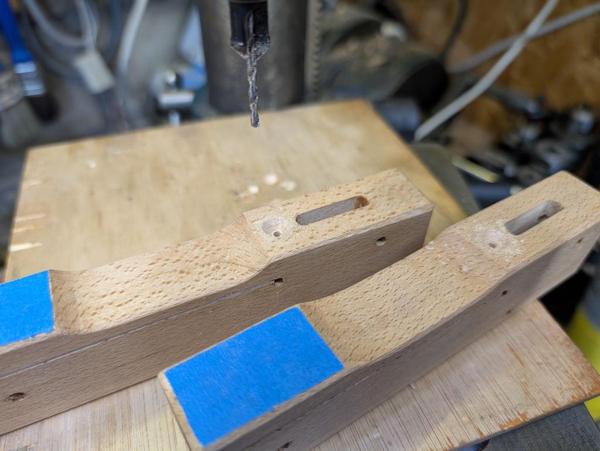
The (4 mm) holes for the roll pins and the (initially 3 mm) hole for the slit end relief got drilled on the pillar drill:

2026-03-14-10-drilling_600.jpg


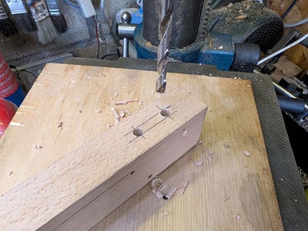
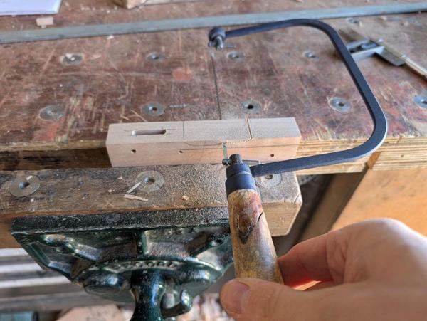
I also drilled the two ends of the bar hole mortice with a 5.5 mm drill. Normally, I'd leave the ends square, but the original clamps had rounded ends so I thought I'd copy that design:

2026-03-14-11-drilling-mortice-ends_600.jpg


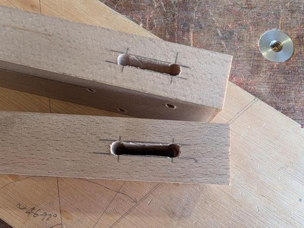
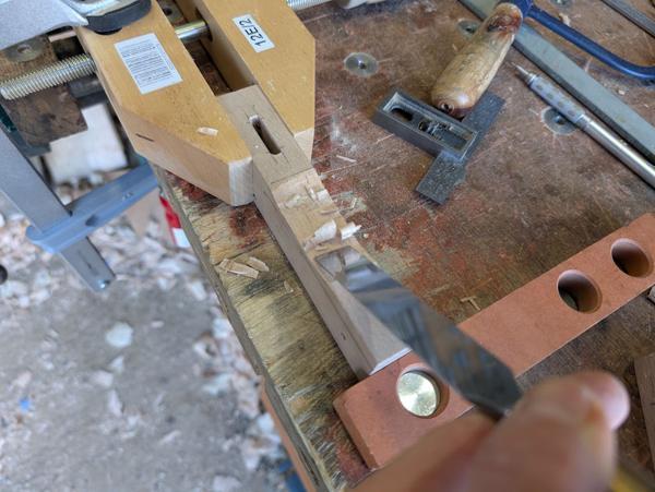
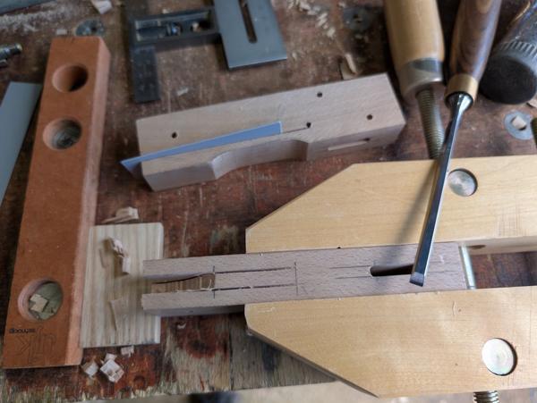
There was then quite a bit of work done with a 4 mm mortice chisel (the next size down I had from the 5.5 mm-ish size of the slot in the existing clamps):

2026-03-14-12-mortice-chisel_600.jpg


The two holes roughed out:

2026-03-14-13-roughed-out_600.jpg


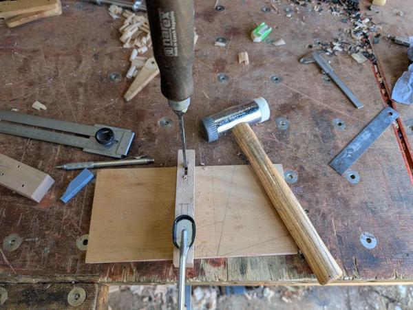
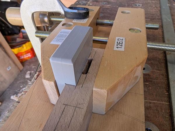
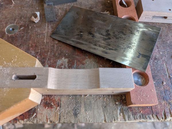
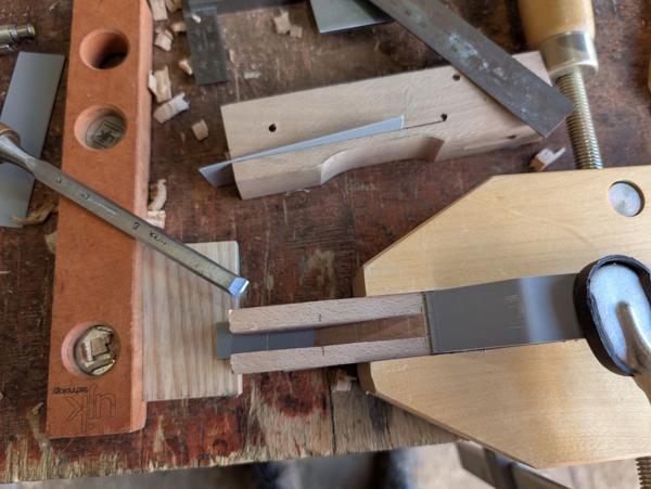
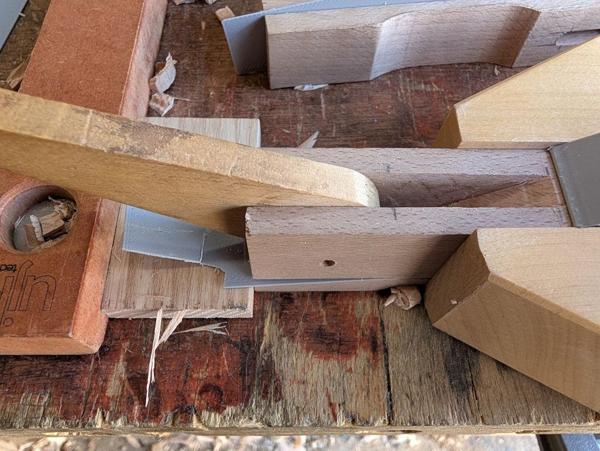
Taking advantage of the fact that my new-ish 3D-printer is much faster than the old one and can knock something like this up in a little over 20 minutes, I printed a little paring guide and used it with an 18 mm chisel to widen the slot:
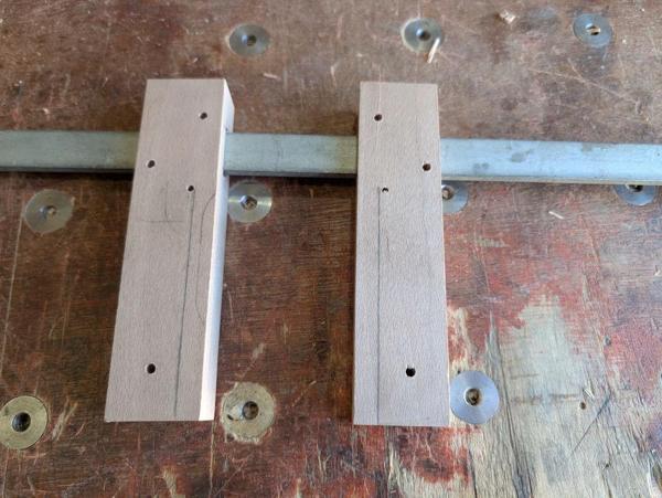
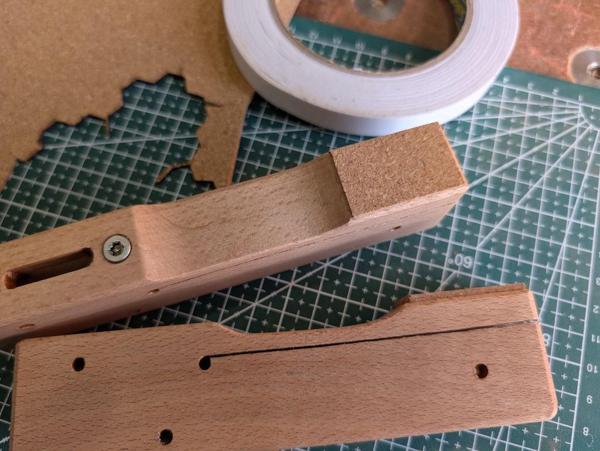
2026-03-14-14-paring-guide_600.jpg


A quick test fit:

2026-03-14-15-fit-test_600.jpg


I've got quite a lot further than that today but that feels like enough for one post so I'll continue with this little adventure tomorrow.
 
I might copy this.
IIRC Steve maskery did a u tube or maybe a magazine article making these.
 
Nice project. It's quite relaxing, isn't it, when you have the whole item beside you to copy. Much better than working from a drawing, I think.
 
Nice project. It's quite relaxing, isn't it, when you have the whole item beside you to copy. Much better than working from a drawing, I think.

It's the first time I've tried working from a real part I think. I usually prefer projects where I'm working to my own designs rather than copying someone else's, but it's been quite pleasant just pottering at the clamp bodies without needing to think too much! Tomorrow morning (when I put the clamps on the bar) I'll find out whether I should have done more thinking!
 
Next up was the curved surface on the moving jaw. I roughed it out with a coping saw...

2026-03-14-16-coping-saw_600.jpg


... then used a chisel bevel-up to get down to the line...

2026-03-14-17-chiselling-curve_600.jpg


... then a card scraper to clean it up a bit:

2026-03-14-17-scraping-curve_600.jpg


I could then do the cut that I was most nervous about: the long saw cut to separate the moving part of the jaw from the fixed part:

2026-03-14-18-sawing-with-wrong-teeth_600.jpg


The eagle-eyed among you will notice that I did the first one with the cross-cut teeth of the Ryoba. On the second one I used the rip teeth, which unsurprisingly cut a lot better!

I was really, really happy with how the two slits went: following the line all the way to the edge of the relief hole.

2026-03-14-19-sawing-done_600.jpg


Just to be on the safe side, I opened the relief hole up (with the pillar drill) to 3.5 mm to make sure the slit and the hole met all the way through the block.

Next up was the open-ended mortice for the cam. On the original clamps, there's a curved surface at the back of the hole, probably as a result of it being cut with a table saw or equivalent. I neither have nor want a table saw and I'd rather do it by hand. I started by sawing down the pencil lines as far as I could:

2026-03-14-20-sawing-open-ended-mortice_600.jpg


There was then lots of chiselling. To minimise the chance of the chisel going through into the moving part of the jaw, I inserted some little 0.6 mm thick plastic shims into the saw kerf:

2026-03-14-21-more-chopping-with-plastic-spacer_600.jpg


That worked really well: when the chisel met the shim, it would tend to push it along (and out of the slot) rather than going through it and into the moving part of the jaw. The last cross-grain cut was done with a little printed paring guide to give a nice smooth finish to the sloped edge of the mortice:

2026-03-14-22-finished-chopping-with-paring-guide_600.jpg


I'd cut that mortice as 8 mm wide, but the cams are 9 mm wide, so I then used an 18 mm chisel to pare the sides down until the cam was a nice smooth fit:

2026-03-14-23-walls-pared-fit-test_600.jpg


The edges then all got chamfered, using my home-made block plane for the straight edges and a thin card scraper for the curved ones:

2026-03-14-24-chamferring_600.jpg


The plastic shims then got re-inserted into the saw kerfs, some masking tape applied to the clamping surfaces (which will get some cork stuck to them) and the bodies given a coat of hard wax oil:

2026-03-14-25-oiled-with-plastic-shims_600.jpg


The cams also got a bit of a clean-up with a card scraper, just taking the minimum off to remove some bits of dirt rather than trying to get an immaculate finish:

2026-03-14-26-scraped-cams_600.jpg


They also got some hard wax oil applied.

I realised after doing the first coat of oil that I still need to drill the hole for the reinforcing screw, so after the first coat of oil had dried, I used a combined pilot drill and countersink to drill a hole in the front face of each of the new clamp bodies:

2026-03-14-27-pilot-and-countersink_600.jpg


The original clamps had slotted screws but as far as I'm concerned slotted screws have no redeeming features whatsoever so there was no way I was going to use them in the repaired clamps. A couple of stainless steel Torx head screws will do nicely:

2026-03-14-28-screws_600.jpg


After the second coat of hard wax oil they were left overnight. This morning I removed the masking tape and used double-sided tape to stick some bits of thin cork onto the clamping faces:

2026-03-15-01-cork-glued-on_600.jpg


I could then assemble the clamps. Despite putting all the roll-pins into a little tray to keep them together, I'd somehow managed to lose one of them. Fortunately, I had a cheap set of roll pins and that included one of the right diameter but much too long. I cut it down to length and used that to replace the missing one.

All the clamps together again:

2026-03-15-02-all-the-clamps-together_600.jpg


A close-up of the repaired clamp:

2026-03-15-03-close-up_600.jpg


As you can see, one of the clamps has the cam pivot hole a little too close to the jaw slit so that even in the fully unlocked position the moving part is slightly out. I could fix that easily by reshaping the cam slightly, but it doesn't affect the function so I'm not going to worry about it.

I don't have an immediate need for these clamps, but I thought it would be good to do a rudimentary test by clamping onto a spare bit of wood:

2026-03-15-04-quick-test_600.jpg


They hold their own weight (which is dominated by the long steel bar) well and didn't need much of the cam motion in order to do so. I think they'll be a useful addition to my clamping arsenal. Many, many thanks again to Graham for sending me these clamps and giving me this little project! Apart from sticking the cork on and reassembling the clamps, the whole project was done in considerably less than a day but it was a very enjoyable and satisfying project.
 
Lovely job.

And the few times I have needed to saw towards a drilled hole, I failed to get the cut to line up nicely, so I shall try to remember to start with a smaller hole and enlarge it. Thanks!
 
Nice job! I really love Klemmsia clamps.

At first I was wondering if beech would be a good choice for this (brittle and not very flexible). But then I remembered the original are made from beech as well. Silly me...
 
Nice job! I really love Klemmsia clamps.

At first I was wondering if beech would be a good choice for this (brittle and not very flexible). But then I remembered the original are made from beech as well. Silly me...

I think the Klemmsia ones are hornbeam if memory serves me correctly. I've no idea whether beech is a good choice for this, it's just what I had. Time will tell whether they last but if they break I can always have another pleasant day making new ones :)
 
Right you are.

But now you got me doubting myself :unsure: , so I took a look at the Feine Werkzeuge website. It says Weißbuche, which is indeed hornbeam.
 
Last edited:
I once had a boxful of these, wooden bar so nice and light. They went into store for a couple of years and came out riddled with woodworm! I could do with having a session making another batch. Next time I shall definitely use roll pins for the wear points.

Excellent job.

S

PS, for anyone making these for the first time, I suggest making that stop hole so that it leaves a minimal amount of wood between it and the slit. Not so much as the thing becomes fragile, of course, but the thinner it is the more flexible it will be.
 
Just looking back at the first photo, I noticed that what you were sent is five heads with cams, three long bars and one fixed end.

Given that the short version has a simple foot, fixed at one end, like this:

IMG_20260315_162327112.jpg

Are you going to make some more simple feet or add some more bars? Or is there any advantage in having both ends equipped with cams?
 
Just looking back at the first photo, I noticed that what you were sent is five heads with cams, three long bars and one fixed end.

Given that the short version has a simple foot, fixed at one end, like this:

View attachment 39976

Are you going to make some more simple feet or add some more bars? Or is there any advantage in having both ends equipped with cams?
I've got a few of those too and I was also surprised to see both jaws having the cams. I guess the advantage is a bit more cam motion (and hence it'll close up a bigger gap). The fixed end would be much easier to make of course so with some extra bars I'd have a lot more clamps.

For now though, I think I'll just leave them as they are. I might make one more cam and fit it to the unbroken head that's now loose, but whether I ever do anything further with it will depend on how often I find myself reaching for these clamps.
 
Back
Top