• Hi all and welcome to TheWoodHaven2 brought into the 21st Century, kicking and screaming! We all have Alasdair to thank for the vast bulk of the heavy lifting to get us here, no more so than me because he's taken away a huge burden of responsibility from my shoulders and brought us to this new shiny home, with all your previous content (hopefully) still intact! Please peruse and feed back. There is still plenty to do, like changing the colour scheme, adding the banner graphic, tweaking the odd setting here and there so I have added a new thread in the 'Technical Issues, Bugs and Feature Requests' forum for you to add any issues you find, any missing settings or just anything you'd like to see added/removed from the feature set that Xenforo offers. We will get to everything over the coming weeks so please be patient, but add anything at all to the thread I mention above and we promise to get to them over the next few days/weeks/months. In the meantime, please enjoy!

Dr Al's Latest Folly

Cabinetman":1q4ic8z1 said:
Yup, I’m sure you will be removing those sharp corners on the tailstock Al, I’m just imagining catching an elbow on one.

Yes, I'm planning on giving everything a fairly thorough going over with a flap disk when it's finished to make sure there's nothing sharp anywhere.

Andyp":1q4ic8z1 said:
Will you be making the chuck as well Al?

No. That sounds far too hard to me (and I'm not sure I need a chuck anyway - at least not for chisel handles, which will probably be turned between centres).
 
The next job was to get on with the part I'm calling the "tool rest slide". This is the bit that will slide along the bed and back and forth and support the tool rest in whatever position I want it. I'm making this as a sort of "t-slot" thing so it can be clamped down in any position. The easiest way I could think of making that (with the bits of steel I have available) is to fabricate it out of some lengths of 12 mm × 35 mm and 10 mm × 20 mm EN3B I had in the drawer:

2515_tool_rest_slide_bits_800.jpg


Rather than welding them together and worrying about distortion, I thought I'd just use M6×50 socket head cap screws. That meant I spent a little while drilling holes, a little while drilling and counterboring holes and a little while drilling and tapping holes...

2516_drilling_1_800.jpg


2517_drilling_2_800.jpg


2518_drilling_3_800.jpg


2519_drilling_4_800.jpg


All the bits with lots of holes in them:

2520_drilled_800.jpg


This shows the pieces half assembled to give an idea of how they go together:

2521_half_assembled_800.jpg


Once they were screwed together, I put the assembly in the mill's vice and used a long end mill to skim the ends flat:

2522_milling_ends_800.jpg


Once both ends were flat, I mounted the assembly to an angle plate and drilled and tapped some holes for some end plates:

2523_drilling_ends_800.jpg


Two more holes were drilled and tapped for attaching the bit that the tool rest will fit to:

2524_drilling_tool_rest_mount_800.jpg


For the end caps, I cut a couple of slices off a bit more 12 mm steel:

2525_rough_sawn_end_caps_800.jpg


That got squared up and milled to size and then some more holes mysteriously appeared:

2526_drilled_end_mounts_800.jpg


This shows where the tool rest will sit:

2527_resting_in_situ_800.jpg


At 57 mm high, it's a lot thicker than it (arguably) needs to be, but with a 128 mm centre height, I'll still be able to turn spindles that are up to 142 mm diameter, which is way bigger than anything I can imagine wanting to turn. If I ever get the urge to try bowl turning, the tool rest slide won't be under the workpiece (I think) so I'd still be able to turn bowls up to 256 mm diameter.
 
A question for those of you who have (or at least have used) a wood lathe:

I recently bought a book ("Woodturning: A Foundation Course"), which has a recommendation for the shape of a tool rest, but it doesn't discuss the height. Are they usually height adjustable? If so, by how much? Adjustable or not, how far below centre height do they usually sit?

I'm guessing that it's common to want to have the top of a tool on centre height (based on the premise that you do that with a metalworking lathe), but presumably that would depend on the tool.
 
The tool rest must be adjustable for height, to cope with different sizes of work and type of cut.

For a thick roughing gouge, you'd want it somewhere below centre height, to accommodate the thickness of the tool. On the same workpiece, if you were taking a planing cut with a skew, you could put it much further up, near the top of the work, depending exactly how you prefer to hold the tool.

Edited to add: That's what I do, but I am not an expert turner. Do also look at p57 of your book, "positioning the toolrest" where Mr Rowley says "the general rule is that the height of the toolrest is not critical in between-centres turning. Fix it at approximately centre height..."
 
AndyT":3aof38fq said:
The tool rest must be adjustable for height, to cope with different sizes of work and type of cut.

For a thick roughing gouge, you'd want it somewhere below centre height, to accommodate the thickness of the tool. On the same workpiece, if you were taking a planing cut with a skew, you could put it much further up, near the top of the work, depending exactly how you prefer to hold the tool.

Edited to add: That's what I do, but I am not an expert turner. Do also look at p57 of your book, "positioning the toolrest" where Mr Rowley says "the general rule is that the height of the toolrest is not critical in between-centres turning. Fix it at approximately centre height..."

Thanks Andy: very useful.
 
.
What Andy said Al.

You need the rest to adjust quickly, smoothly and easily not only in height but in and out to accommodate the thickness of any wood you want to turn as you want to keep the rest close to the work to avoid stress and chatter from the tool, you'll also need to be able to turn the rest itself by 90 deg and anything in between for face work. That means the shaft should be a round bar and the locking mechanism should be via handles not having to use tools, it also needs to be easily removable. I've made rests in the past and they aren't difficult, with your skills and tooling it will be a doddle.

The rest itself can be a round bar just welded on top of the shaft ( even I managed that with poor welding skills :) ) and it would be useful to have at least one short and one long version. It can also be rectangular with a rounded top, also if you ever turn a bowl a bent toolrest can make things easier though not essential. there needs to be room so you can angle the tool unlike a metal lathe which is horizontl at work centre. The rest doesn't have to be hardened but it will nick and need smoothing occasionally especially if you use HSS tools.

Here are some pics of mine if they help but there are a numer of other designs and mechanisms around.
 

Attachments

  • IMG_1948.JPG
    IMG_1948.JPG
    299.5 KB · Views: 450
  • IMG_1949.JPG
    IMG_1949.JPG
    220.2 KB · Views: 450
  • IMG_1950.JPG
    IMG_1950.JPG
    318.3 KB · Views: 450
I find the skew scary. Except when I keep it flat, cutting almost on top of the work. I'd make sure the toolrest can get that high because when turning handles, you really only need the skew.

Except when making those beautiful London Pattern handles (don't know if this is the correct term, I mean those where the handle is partially octagonal). In which case, you could provide for some way to index the facepate/chuck. I've seen people plane the flats without taking the wood of (off? don't know, Dutchie here) the lathe.

Although I don't post much, I've seen all your build threads and I for one don't believe you won't built a chuck :)

Good luck from another member who is enjoying these builds immensely.
 
It's just practice and more practice Rob, do it on scrap wood so if you get a dig in it doesn't ruin anything. Easy to say but confidence is a key and you have to just hold firmly, cut at an angle and use the lower third of the cutting edge so you get a planing cut polished by the bevel.
I have a few skews and use them more than anything else, including taking the corners off square timber, rounding ends and using the point. A standard skew is easier but I find the oval one more versatile.

Just my way of working, there are as many ways as there are turners.
 
Lons":w42f6w64 said:
You need the rest to adjust quickly, smoothly and easily not only in height but in and out to accommodate the thickness of any wood you want to turn as you want to keep the rest close to the work to avoid stress and chatter from the tool, you'll also need to be able to turn the rest itself by 90 deg and anything in between for face work. That means the shaft should be a round bar and the locking mechanism should be via handles not having to use tools, it also needs to be easily removable. I've made rests in the past and they aren't difficult, with your skills and tooling it will be a doddle.

Thanks Bob. I'd already planned for the round bar and for handles for adjusting the positions, so that's all good I think. How much height adjustment do you think it needs (above and below centre height)? That sort of thing makes quite a bit of difference to how long the round bar needs to be and how much clearance needs to be allowed for it.

Lons":w42f6w64 said:
The rest itself can be a round bar just welded on top of the shaft ( even I managed that with poor welding skills :) ) and it would be useful to have at least one short and one long version. It can also be rectangular with a rounded top, also if you ever turn a bowl a bent toolrest can make things easier though not essential. there needs to be room so you can angle the tool unlike a metal lathe which is horizontl at work centre. The rest doesn't have to be hardened but it will nick and need smoothing occasionally especially if you use HSS tools.

Here are some pics of mine if they help but there are a numer of other designs and mechanisms around.

That's very helpful indeed and looks a lot simpler (and easier to make) than the version in the book I've got. I'm going through my steel stock like it's going out of fashion, but I'll have a dig around when I get a chance and see what I can find that might work. Thanks again.

RAF":w42f6w64 said:
I find the skew scary. Except when I keep it flat, cutting almost on top of the work. I'd make sure the toolrest can get that high because when turning handles, you really only need the skew.

That's useful to know: I don't think I would have considered raising the tool rest that high.

RAF":w42f6w64 said:
Except when making those beautiful London Pattern handles (don't know if this is the correct term, I mean those where the handle is partially octagonal). In which case, you could provide for some way to index the facepate/chuck. I've seen people plane the flats without taking the wood of (off? don't know, Dutchie here) the lathe.

If you drift back to page 2 of this thread, you'll notice that the current design has a bunch of holes (12 of them) in the pulley. The intention of those holes was to use for indexing the head. I might now end up with a smaller pulley (to get the speed up), but I can always swap it out for an indexing plate if necessary.

RAF":w42f6w64 said:
Although I don't post much, I've seen all your build threads and I for one don't believe you won't built a chuck :)

:lol:

You're going to be sorely disappointed I'm afraid: there's a reason I picked a standard thread for the chuck mount! Making a chuck would involve a heck of a lot of milling and I don't especially enjoy milling, especially on my little baby milling machine, so the idea of making a chuck doesn't especially appeal to me.

RAF":w42f6w64 said:
Good luck from another member who is enjoying these builds immensely.

Thanks Rob.

GaryR":w42f6w64 said:
This has all been so wonderfully informative, Al and others. Lots to digest!

Thanks Gary, I'm glad you're enjoying it (I'm enjoying your WIP too!)

Cabinetman":w42f6w64 said:
Fascinating as ever, I await to see how you will tighten down that slider, clever stuff through the end? Or raise the whole lathe up and a lever underneath Myford style.
Ian

It's going to be adjustable from the end (that's what the holes in the end plates are for). I've got a cunning plan for how that will work, but you'll have to wait to see the details :D
 
The adjustment on my standard as provided rests is around 100mm Al and the last one I made a bit more at 120mm, the shafts are obviously longer than that to allow a secure bed in the rest base.
Without looking back I think you said 128mm centre height so the max cylinder you could mount is probably 200mm or so allowing for the base of the rest under the work which would be similar to mine.
 
Lons":1d2oab5a said:
The adjustment on my standard as provided rests is around 100mm Al and the last one I made a bit more at 120mm, the shafts are obviously longer than that to allow a secure bed in the rest base.
Without looking back I think you said 128mm centre height so the max cylinder you could mount is probably 200mm or so allowing for the base of the rest under the work which would be similar to mine.

Blimey, that's quite a bit of adjustment. Is that ±50 mm relative to centre height or is it biased one way?

I'm not sure whether I'll manage quite that much (there's only 71 mm from the top of the "tool rest slide" to centre height and I need some of that for the thing that the bar will be clamped into).

:eusa-think:
 
Morning Al, I couldn’t find a tongue in cheek smilie when I asked about chuck making. :)

I have never had a woodwork lesson in my life ( it probably shows) EXCEPT for wood turning. I really think that you would benefit a lot from even an half day course. I spent a day with a woodturner here and even with my basic level of french I learned a lot and especially gained confidence. I have never used a metal lathe and am no expert in woodturning but I would proffer that there is a lot more “feel” required when wood turning than metal turning even for tool handles.
Any woodturning clubs nearby? They would no doubt make you welcome and if you took along your lathe I am sure they would be very interested and willing to offer a bit of hands on training.

Edit
Not too far from you I think
https://www.gaw.org.uk/blog/wordpress/
 
Andyp":21xpqp1x said:
I have never had a woodwork lesson in my life ( it probably shows) EXCEPT for wood turning. I really think that you would benefit a lot from even an half day course. I spent a day with a woodturner here and even with my basic level of french I learned a lot and especially gained confidence. I have never used a metal lathe and am no expert in woodturning but I would proffer that there is a lot more “feel” required when wood turning than metal turning even for tool handles.
Any woodturning clubs nearby? They would no doubt make you welcome and if you took along your lathe I am sure they would be very interested and willing to offer a bit of hands on training.

That's definitely good advice. I've no idea about local clubs, but I have a fairly useful fall-back option if all else fails: my father took up wood turning when he retired :)

My original plan for these chisel handles was to take the walnut down to my parents' house when I visited over the Christmas break, but covid put the kibosh on that plan and the next time we met up I was spared the unpleasantness of the South-East of England as we met up half-way instead.

Whenever we do next visit their house I'm sure he'd be very happy to give me some tuition.

I'm also booked onto a 2-day green woodworking / pole lathe course in May; while it's not directly applicable, I'm sure it'll help in some ways.
 
Dr.Al":24meyxs9 said:
Lons":24meyxs9 said:
The adjustment on my standard as provided rests is around 100mm Al and the last one I made a bit more at 120mm, the shafts are obviously longer than that to allow a secure bed in the rest base.
Without looking back I think you said 128mm centre height so the max cylinder you could mount is probably 200mm or so allowing for the base of the rest under the work which would be similar to mine.

Blimey, that's quite a bit of adjustment. Is that ±50 mm relative to centre height or is it biased one way?

I'm not sure whether I'll manage quite that much (there's only 71 mm from the top of the "tool rest slide" to centre height and I need some of that for the thing that the bar will be clamped into).

:eusa-think:

Sorry Al, I've had a mind melt epidode there somewhere, old age galloping forward ios my only excuse.

The total shaft length on mine is around 100mm on the std rest and 120 on the home made. You rarely need to set the rest much below centre but can need to be near the top of the material so the adjustment would only be around 60mm on mine and 20mm more on the last one I made. I'll check when I'm in the workshop later.
 
I had a hour or two free this evening so I popped out to do a bit more on the tool rest slide. Following advice on tool rest height adjustability, I've decided to abandon the two tapped holes I'd originally planned to use for holding a tool rest support in place. Working on the other end of the tool rest slide, I used a spot drill to position some (very carefully thought-out) hole locations:

2701_spot_drill_800.jpg


The holes were then completed. The outside ones were drilled and tapped M6; the middle one was drilled out to 16 mm, finishing with an end mill for final sizing:

2702_drilled_and_tapped_800.jpg


I then flipped the tool rest slide over and milled a clearance slot at the bottom:

2703_clearance_800.jpg


The eagle-eyed among you will note that I've also added a small drilled hole in the end plate (and a matching one at the other end).

Next up was a bit of 40 mm EN1A, which was mounted in the three-jaw chuck, drilled, bored and reamed to 16 mm.

2704_bored_and_reamed_800.jpg


After parting off, reversing and cleaning up the back face, it was then mounted (in a somewhat precarious way as I was being lazy and only drilling, not milling) and the axes zeroed on the centre of the bore:

2705_clocking_centre_800.jpg


Three holes could then be drilled and counterbored:

2706_counterbored_800.jpg


I did those holes in a slightly odd order: I spot drilled them, drilled them to 24 mm depth, counterbored them, then completed the through hole. The reason for that was that the vice mount was a bit precarious (it would have been better to have a v-block between the part and one of the jaws) and I wanted to leave the parallels in place until the last minute.

Once those holes were done, I shoved a couple of drill bits in the holes and used them to align it in the vice such that a drilled and tapped hole would go roughly central between the two tapped holes:

2707_cross_tapped_800.jpg


It could then be mounted to the tool rest slide and tested with a bit of 16 mm silver steel bar and a handy cap screw (which will get replaced with a knob of some sort in due course):

2708_test_fit_800.jpg


It was starting to feel like I was getting close to the finish line, so I thought I would check my ambitions somewhat by writing down a list of all the parts I could think of that still needed to be made. There were 44 of them! I'm still a fair way from completion.

Admittedly, some of those 44 are really simple things like the handle for the tailstock handwheel, which is basically a tube. However, some of them are complex (and possibly made up of multiple parts) like the motor mount and the bed/feet assembly, neither of which I've really started to think about yet.
 
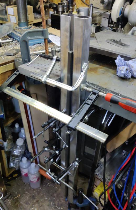
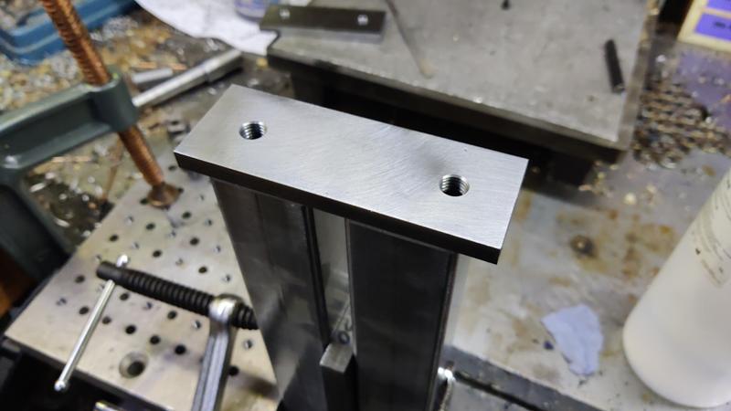
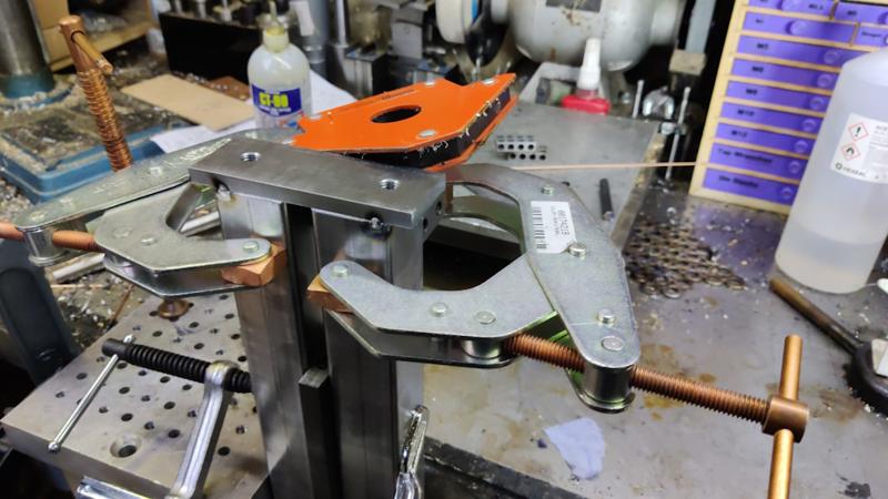
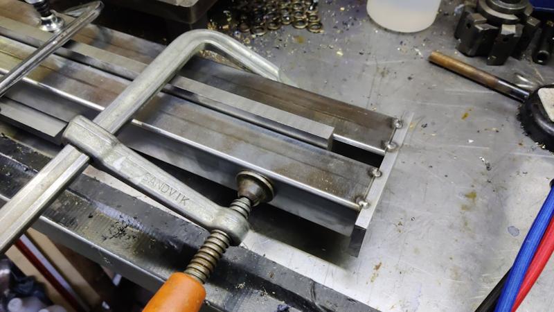
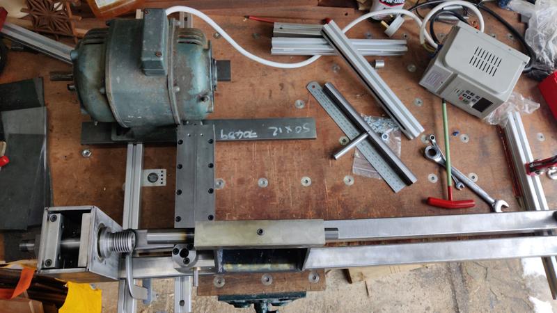
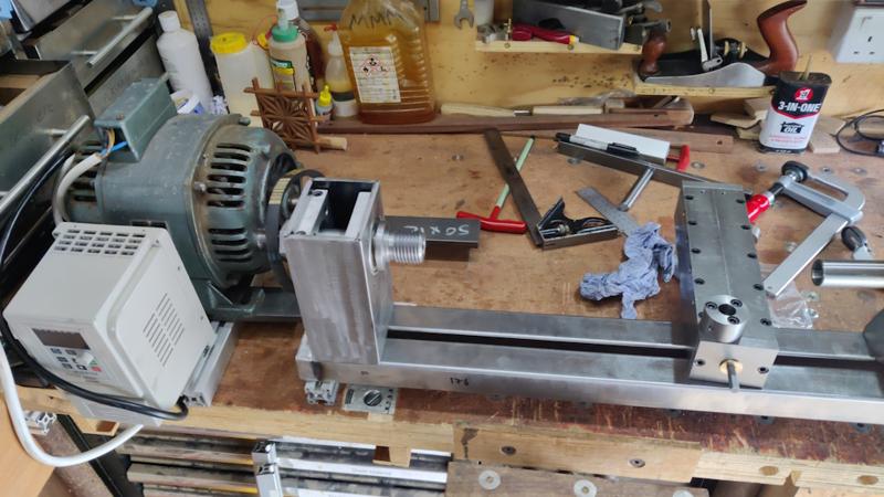
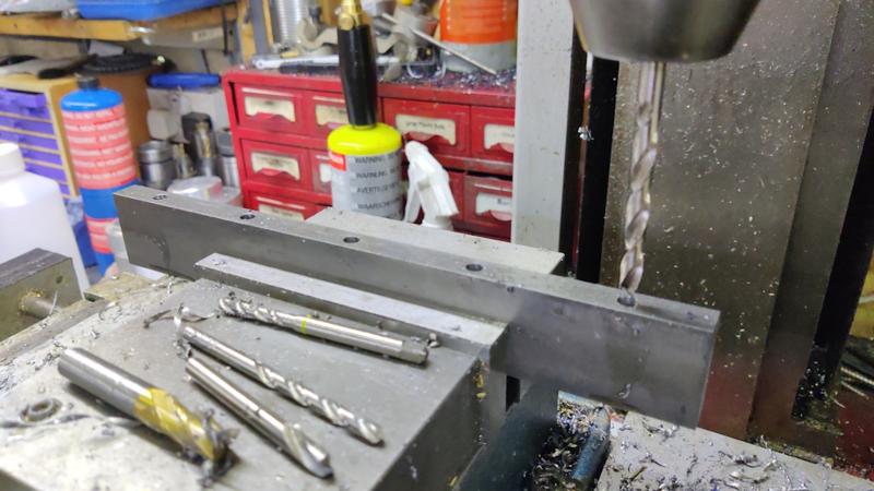
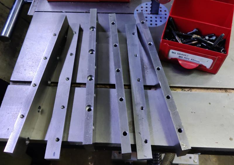
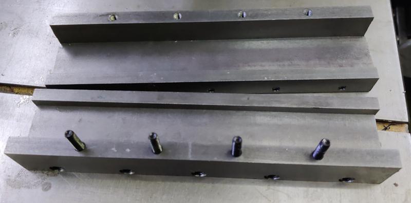
I've been working on the tool rest slide mechanism gradually in amongst other jobs, but I thought I'd wait until it was mostly complete before posting the photos and build process as I figured it would make more sense as a fait accompli.

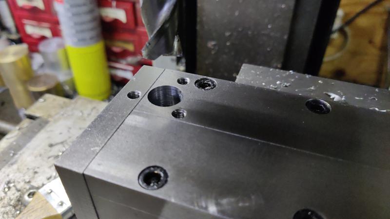
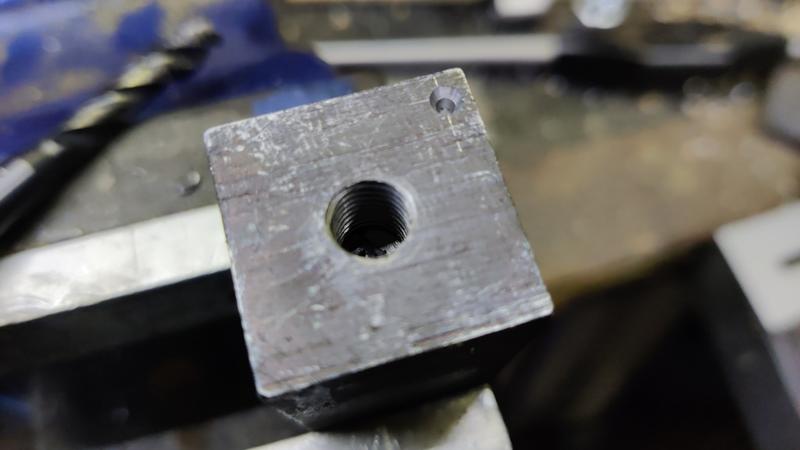
The first piece to describe is the part I'm calling the clamp block. This sits inside the "t-section" of the tool rest slide and can move along to any position along the length. When the tool rest slide is clamped, this piece is the one that presses down on the tool rest slide and holds it in place.

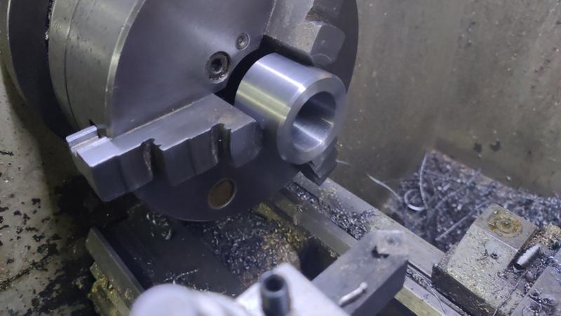
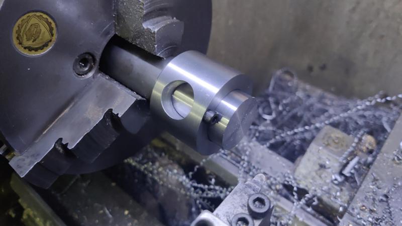
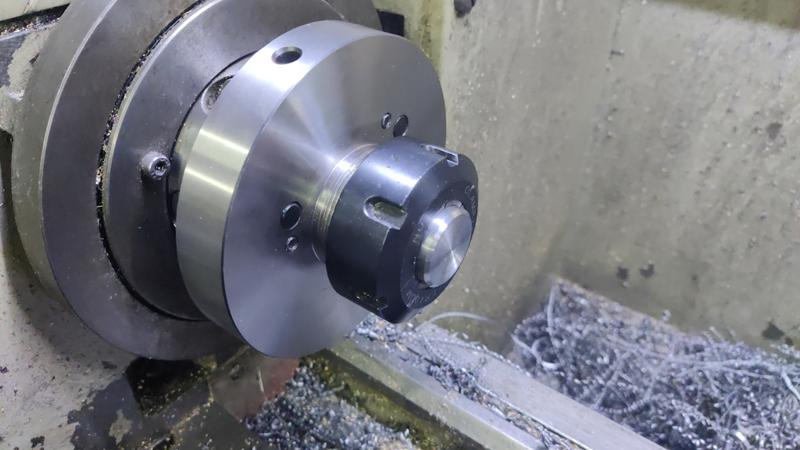
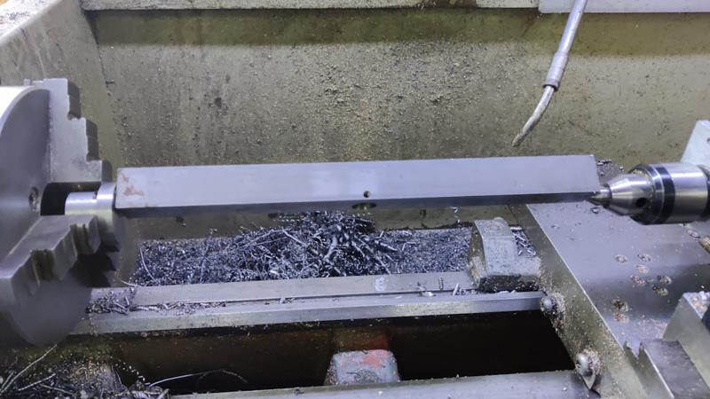
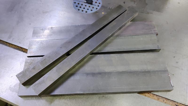
I started with a length of 50 mm diameter EN1A. It's too large to go through the chuck, so I used a fixed steady to support the outer end while I turned the outer diameter down to a bit less than 46 mm and bored a (slightly under) 30 mm hole through the middle:

clamp_block_01_shaping_50mm_steel_800.jpg


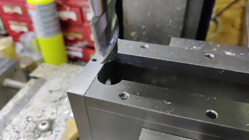
After cutting the end off with the bandsaw, I put it back in the chuck the other way round and faced the end. I also added a heavy chamfer to this end so that it was obvious which end had been faced in the same setting as the central bore. The chamfered end will be the top and it doesn't matter if that isn't perfectly square to the bore.

clamp_block_02_reversed_and_faced_800.jpg


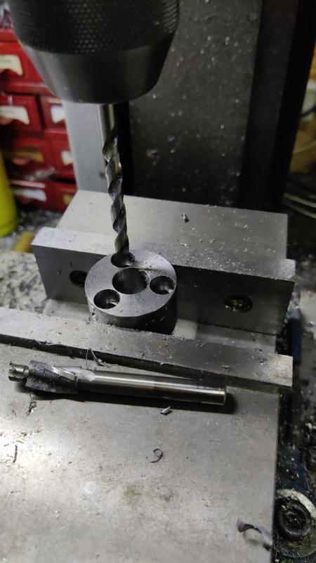
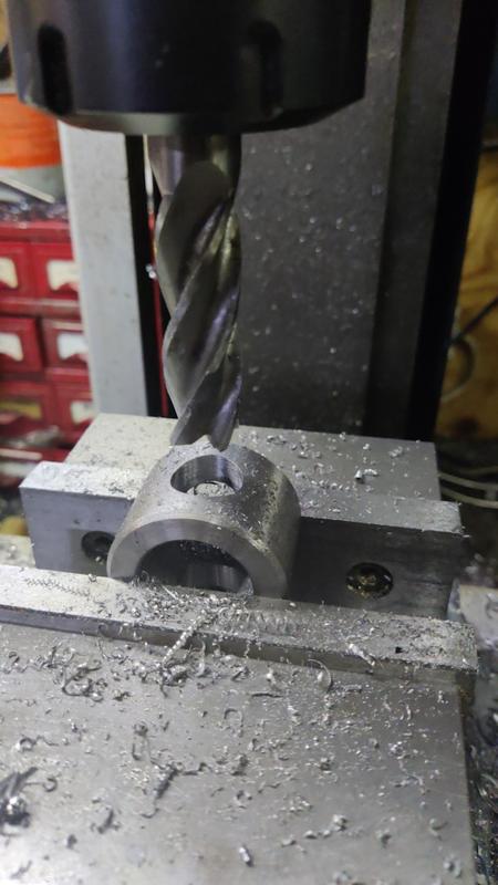
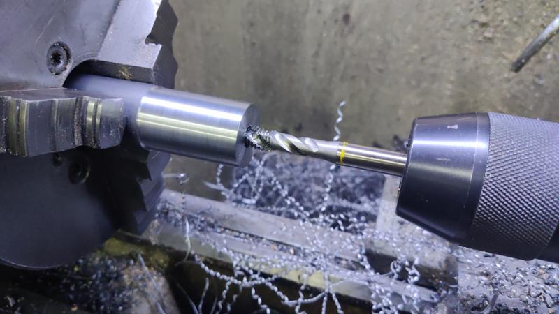
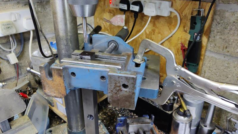
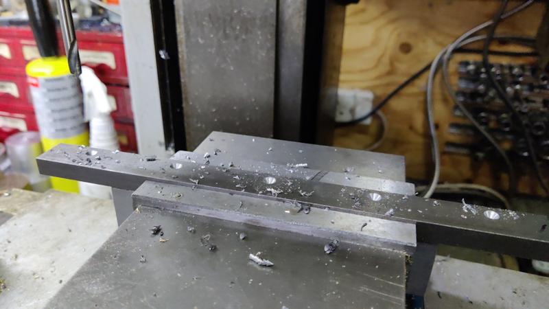
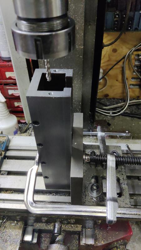
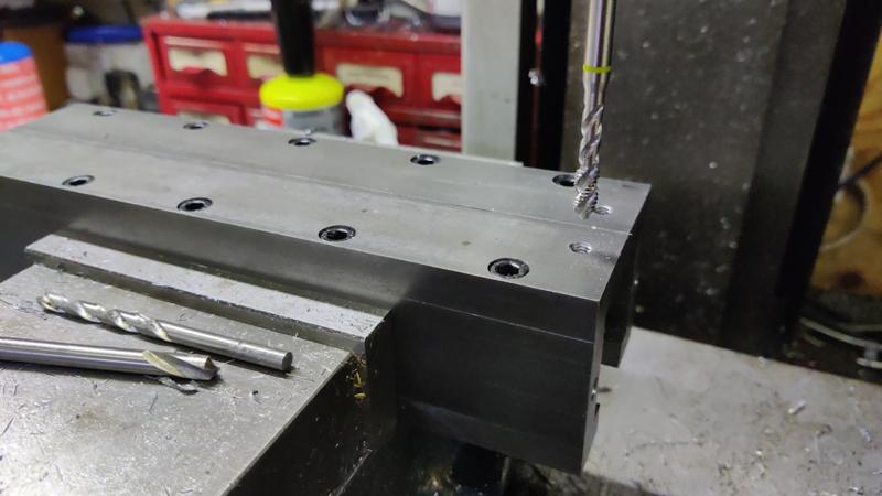
The part then got clamped in the mill vice and I drilled an 18 mm cross hole, 16 mm from the base. I did this with drill bits up to 13 mm and then 14 mm, 16 mm and 18 mm end mills to bring the hole to the final size:

clamp_block_03_drilling_18mm_800.jpg


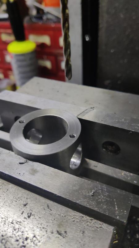
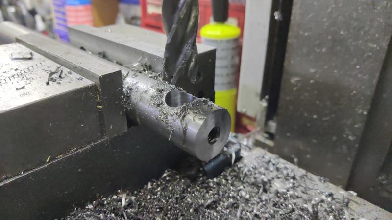
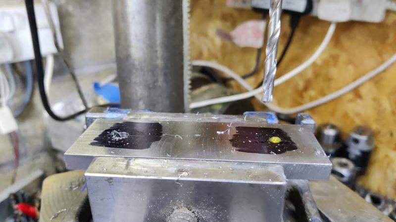
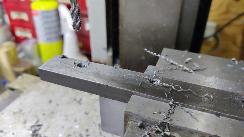
It was then placed in the vice in the other orientation with the base facing upwards. I aligned it (very roughly) by lying a bit of 12 mm (the first piece that came to hand!) bar through the 18 mm cross holes and rotating the clamp block until it looked about right. Again, it would have been better to use a V-block for better clamping, but I didn't have one that was big enough and I'm only drilling so I didn't think it was important. With it clamped in the vice, I spot drilled and drilled two 3.3 mm holes:

clamp_block_04_drilling_for_lock_screws_800.jpg


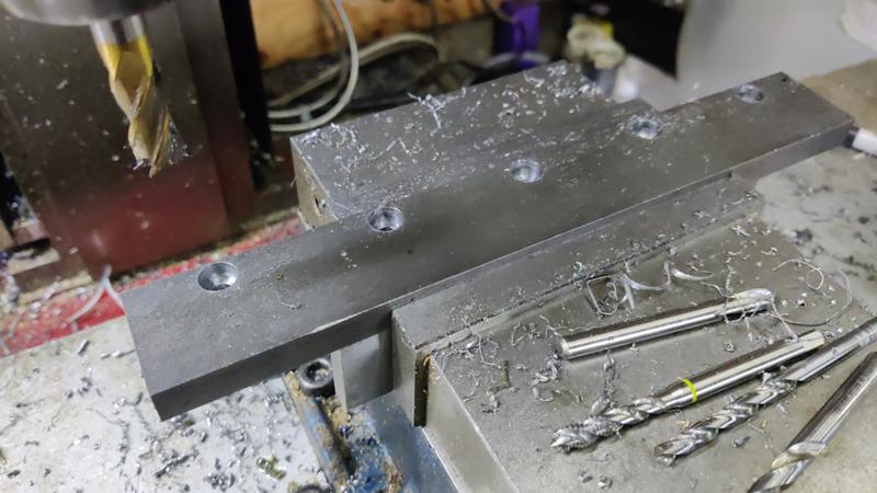
Those holes then got tapped M4, but I did that by hand in the bench vice rather than trying to machine tap while the part was held rather weakly in the machine vice.

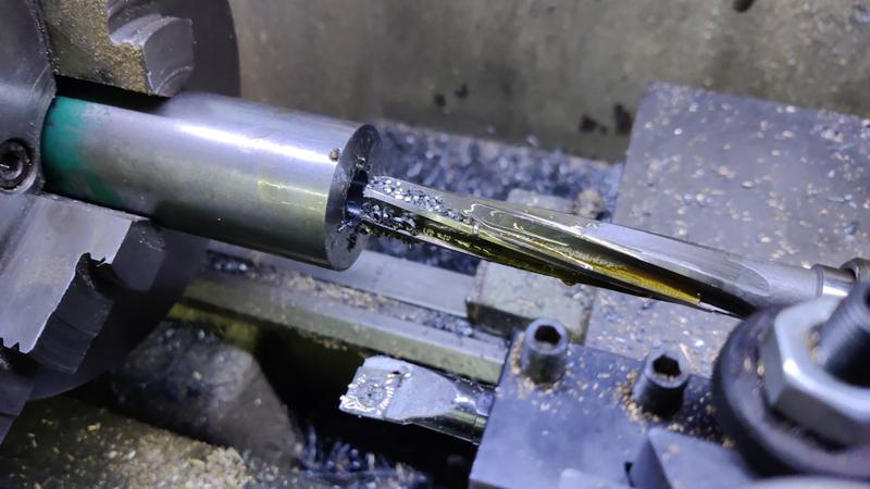
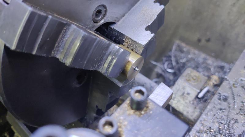
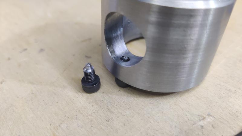
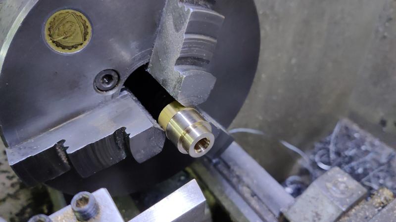
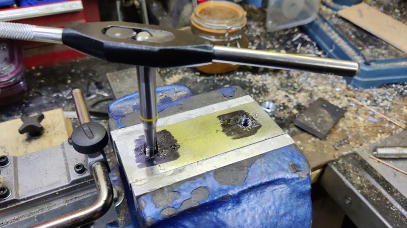
I then needed some modified M4×8 cap screws for those holes. The screws need to have a short 2 mm diameter section on the very end. To hold them for modifying, I drilled and tapped an M4 hole in an offcut of brass and then used an end mill to bore through most of the hole, leaving a flat bottom and about 5 mm of thread remaining. That could then be mounted in the chuck and I could tweak the end of the cap screw. I had to do this with the tool upside down and the lathe running backwards; otherwise the cutting force would have just unscrewed the cap screw from the brass bit.

clamp_block_05_shaping_lock_screws_with_lathe_running_backwards_800.jpg


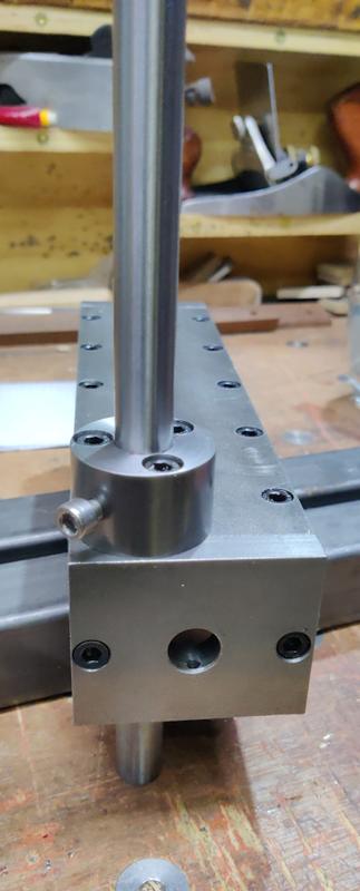
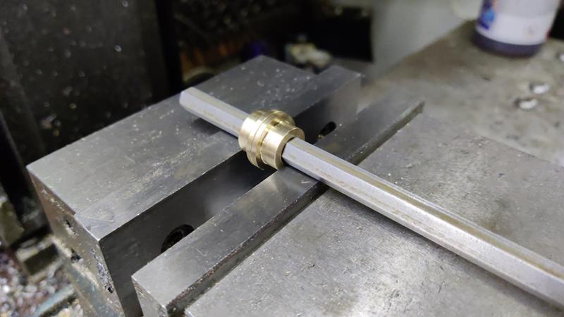
This photo shows one of the modified screws on the bench and another fitted into the threaded hole in the clamp block:

clamp_block_06_lock_screw_detail_800.jpg


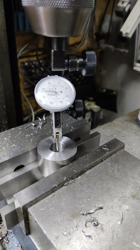
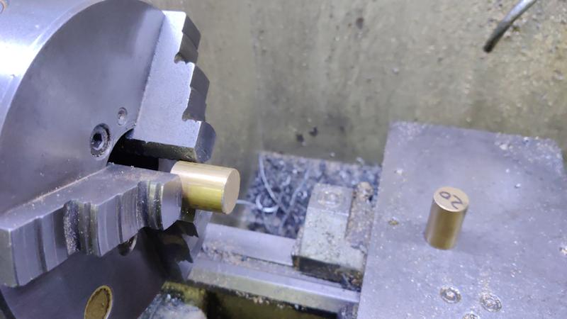
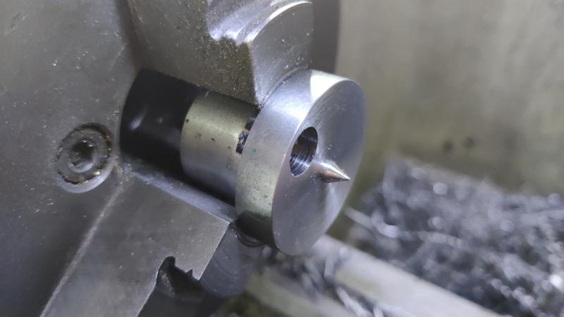
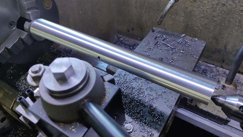
The "clamp nut" is made from 30 mm EN1A. I'm calling it a clamp nut, but it's really a screw that happens to be made in two parts: the "nut" with an internal thread and a bit of threaded rod glued into that thread. I started by skimming the outside diameter until it was a nice smooth sliding fit in the clamp block:

clamp_nut_01_sizing_outside_diameter_800.jpg


I then drilled and tapped a blind M10 hole, about 15 mm deep:

clamp_nut_02_tapping_m10_800.jpg


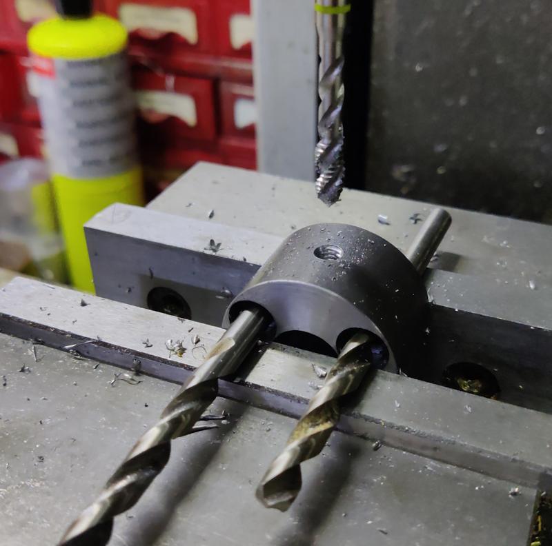
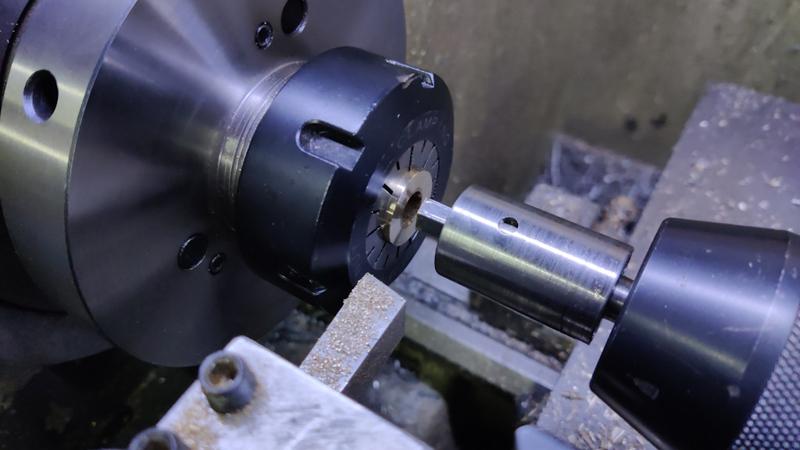
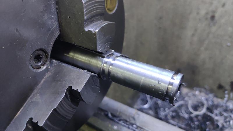
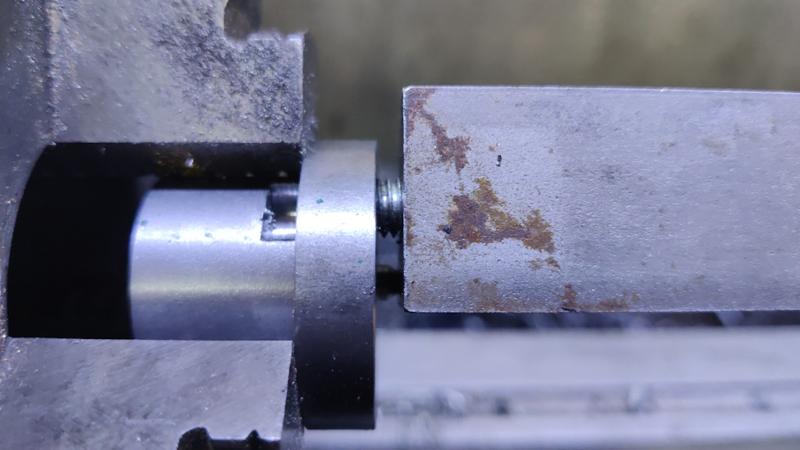
The bar then got clamped in the mill vice and an 18 mm hole cross-drilled, in the same way as was done for the clamp block:

clamp_nut_03_drilling_18mm_800.jpg


Finally (for this part), the clamp nut was sawn off the bar and held in a collet chuck for facing/chamfering the top end.

clamp_nut_04_facing_end_800.jpg


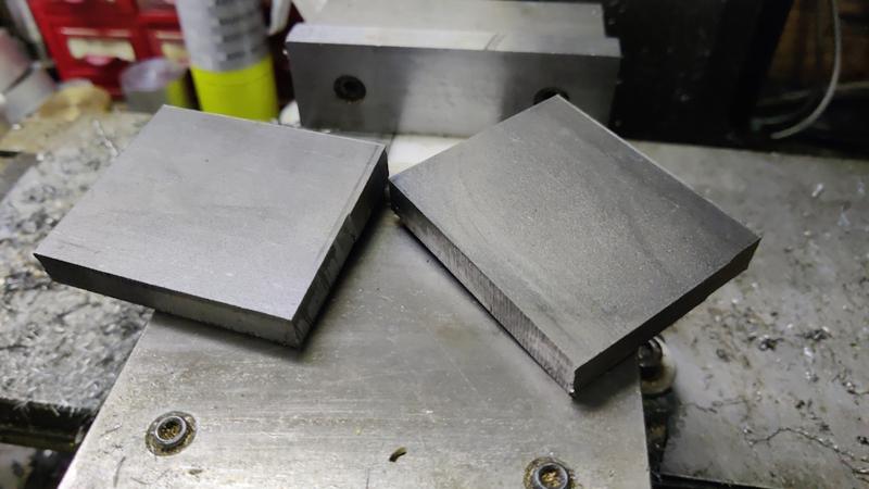
The next job was to make a couple of end caps / bushes. These started life as a couple of offcuts of 20 mm brass bar:

endcaps_01_offcuts_800.jpg


The first job was to shape the end, reducing the diameter to 15 mm for 6 mm length and skimming the outside diameter for a clean look. An 8 mm hole was drilled through and then opened up to 9.2 mm for a couple of millimetres:

endcaps_02_shaped_end_800.jpg


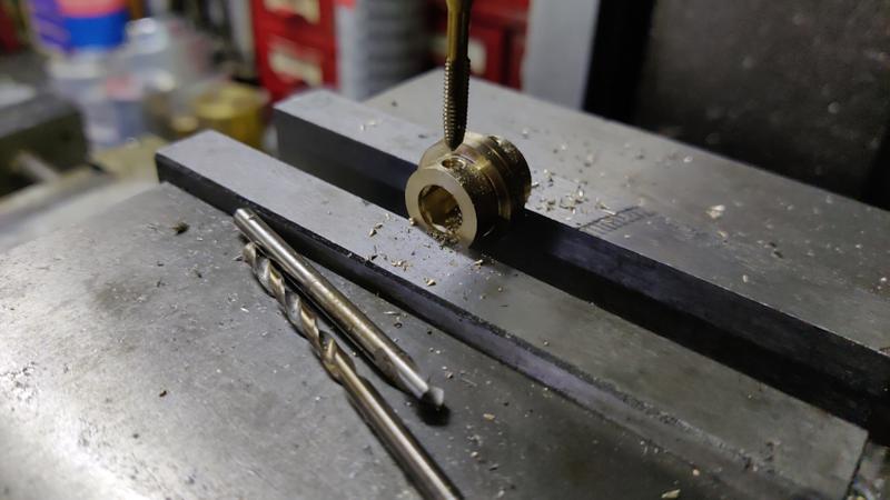
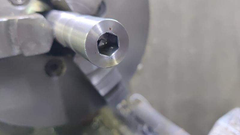
After parting off, it was mounted in a collet (with the other one at the back end of the collet to help ensure that the collet held tightly on this short part) and the end was faced. I used my Hemingway Kits rotary broach to turn the 8 mm hole into an 8 mm deep 8 mm AF hex hole:

endcaps_03_reversed_and_broached_800.jpg


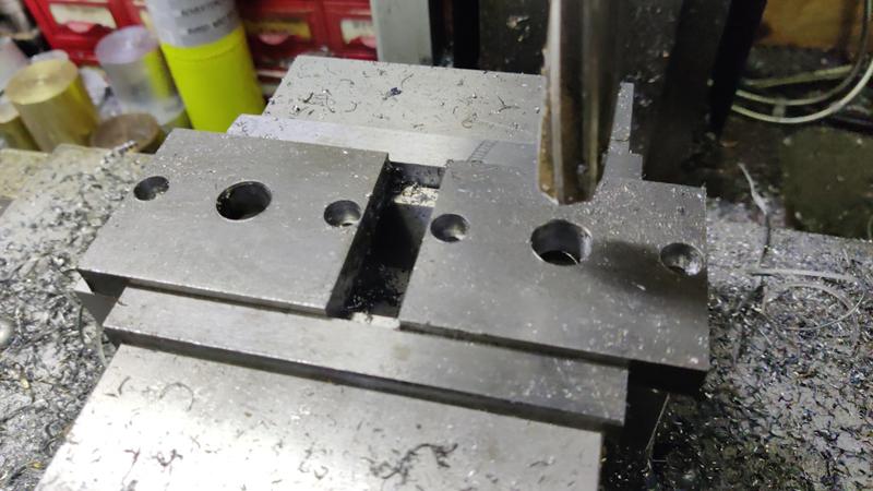
These parts need a cross-hole for a grub screw, so I mounted them together in the mill vice, using a length of 8 mm hex bar to align the internal hex hole with the jaws of the vice:

endcaps_04_aligning_in_mill_vice_800.jpg


I could then drill and tap an M4 hole in each piece:

endcaps_05_drilled_and_tapped_800.jpg


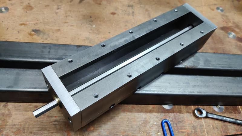
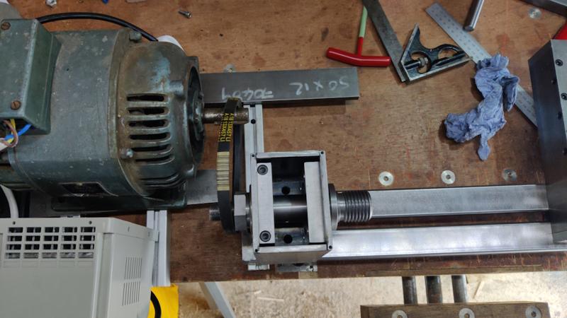
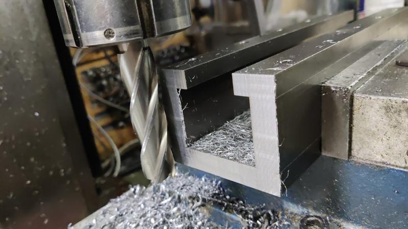
This photo shows how those end caps fit into the end plates of the tool rest slide and support the hex bar that runs along the length. This photo was taken before I drilled the extra holes in the bottom of the tool rest slide that give access for a 2 mm Allen key for tightening/loosening the grub screws that hold the brass bushes/end caps onto the hex bar. The brass bushes rotate freely in the holes in the end plates and hence the hex bar can be rotated freely.

endcaps_06_test_fit_800.jpg


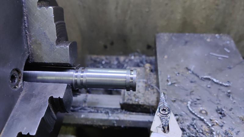
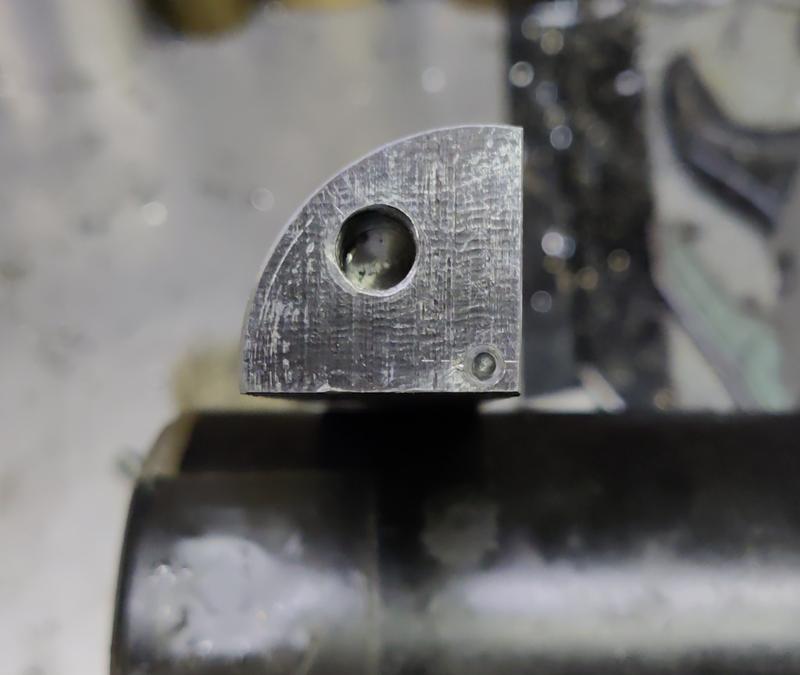
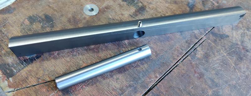
That brings us to the last piece of the puzzle. I started with a bit of 18 mm round bar and, after facing the end square, I used a 2 mm wide parting tool to cut two grooves in the part (and also to mark the length of the bar - that's the groove nearest the chuck):

cam01_cutting_grooves_800.jpg


An 8 mm hole was drilled through the part and then the rotary broach was used to turn it into an 8 mm AF hex hole, going as deep as the tool would allow (which is about 8 mm):

[youtubessl]SnAOvYzryZ4[/youtubessl]

The resulting hole:

cam04_broached_hole_800.jpg


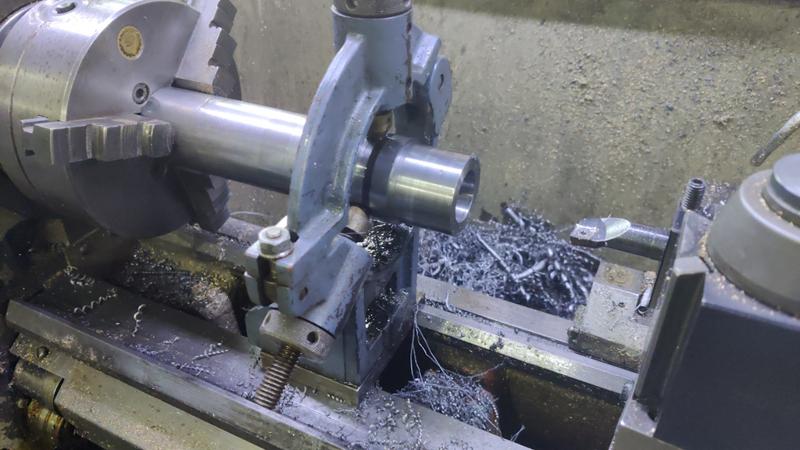
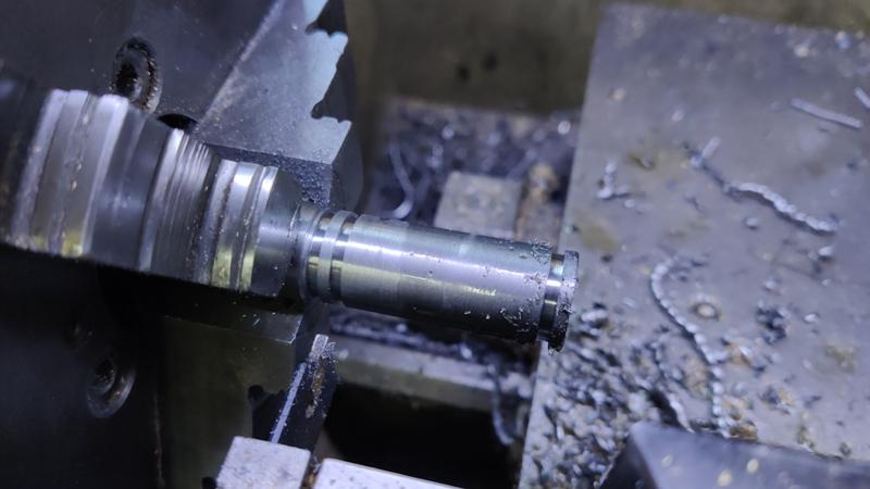
With the hole cut, I could work on the eccentric cam section. I added an 0.8 mm piece of feeler gauge stock to one of the jaws of the chuck:

cam02_0.8mm_shim_800.jpg


I could then use a pointy tool to cut the central section of the piece. I wasn't aiming for a specific diameter here, I just kept taking passes until the tool was cutting continuously:

cam03_cutting_cam_800.jpg


The final operation on this part (for which I didn't take any photos) was to cut it off the bar, mount it the other way round in the collet chuck and face the back end. I then used a 9.2 mm drill bit to drill most of the way through the part, leaving the final 8 mm-ish. The reason for that final drilling operation is that I want an 8 mm hex bar to pass all the way through the cam. My rotary broach will only cut about 8 mm deep, so the rest of the length has to be drilled wider to allow the across-corner dimension of the hex bar to go through. Theoretically this dimension is 8×2÷√3 = 9.238 mm, but I measured the size of my hex bar and it was slightly under 9.2 mm.

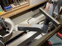
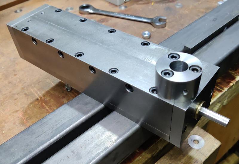
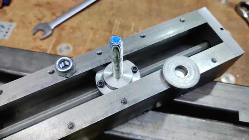
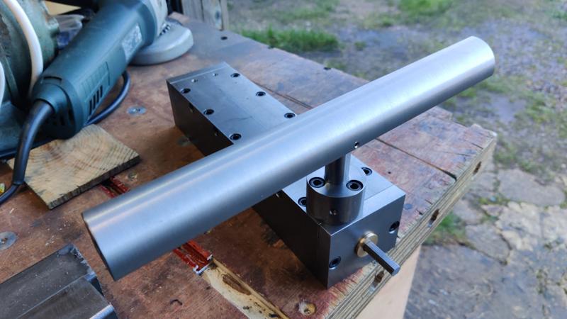
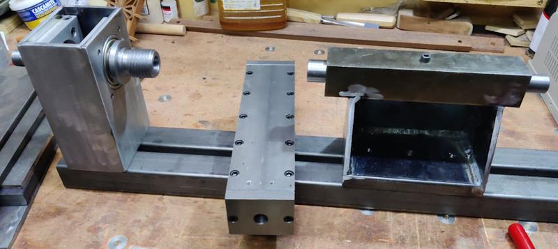
With the final part made, I could assemble the tool rest slide:

tool_rest_slide_assembled_800.jpg


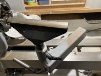
This shows the underside of the assembled tool rest slide:

tool_rest_slide_underside_800.jpg


The two modified M4 cap screws engage with the grooves in the cam and stop it from sliding out of the clamp block. Rotating the cam section lifts or lowers (under gravity) the clamp nut (and hence the M10 threaded rod). The big washer and the nyloc nut bear against the bottom of the bed.

As the threaded rod is round, the tool rest slide can be rotated to any angle. As the clamp block / clamp nut / cam assembly can slide freely along the hex bar, the tool rest slide can be moved back and forth across the bed (as well as along the bed). Rotating the hex bar (via a yet-to-be-made handle) by about 90° is enough to release/lock the tool rest slide to the bed.

This very short video shows the action of the lock (using an 8 mm spanner as a temporary lock handle and with the "bed" bodged as two bits of box section clamped round some 12 mm plate and then clamped to the bench).

[youtubessl]5kcUrEaHITs[/youtubessl]

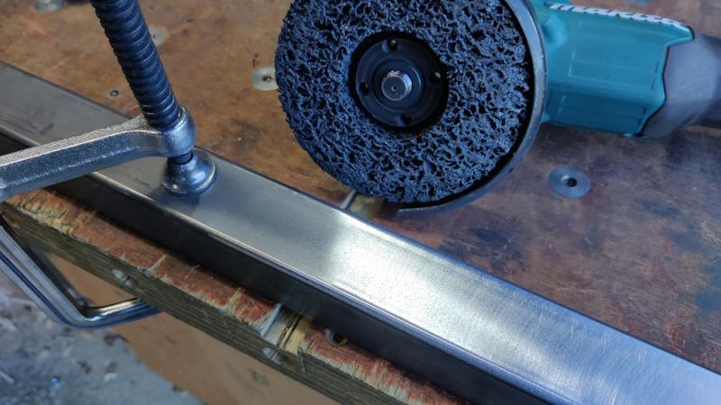
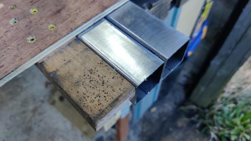
I spent quite a lot of time thinking about how to make the tool rest slide (not least making a hex hole for a 45 mm long cam to slide along a hex bar) and I'm really pleased with how it's working. The action of sliding is a little bit rough, but that's just because of the rough finish on the box section. It should be very quick and easy to adjust the position of the tool rest with this mechanism.
 
Now that's very clever!
I think I had already twigged that you are good at this sort of thing, but to have held all that in your head for long enough to make it is really rather impressive. I think you will feel a sense of satisfaction every time you adjust the tool rest.

And the rotary broach is a nice bit of dark magic too :? :)
 
AndyT":26mkm8y5 said:
Now that's very clever!
I think I had already twigged that you are good at this sort of thing, but to have held all that in your head for long enough to make it is really rather impressive. I think you will feel a sense of satisfaction every time you adjust the tool rest.

And the rotary broach is a nice bit of dark magic too :? :)

Thanks Andy
 
That's a very clever way to hold the M4 cap screws Al, I had something similar with some M6 and really struggled, never thought of doing that. You learn a little every day or a lot in the case of this thread. :eusa-clap:

That slide is smoother than the one on my Axi
 
Thanks all.

Bob: regarding holding cap screws, google "lantern chuck". That's my normal way of doing it. I went with the brass thing as I couldn't find the M4 adaptor for my (home-made) lantern chuck & was too lazy to make a new one.
 
Thanks Al, I'll look at those. I'm not sure if I can find one for my tiny lathe which is M14x1mm but I might be able to knock something up.
 
I’m learning a great deal here, thanks Al. I think I would have enjoyed metalwork but conscious that I would find it very hard (at first!) to stop myself from brushing the swarf away, also it’s a good bit dirtier than woodwork by the look of it.
 
Lons":zkxxk20b said:
Thanks Al, I'll look at those. I'm not sure if I can find one for my tiny lathe which is M14x1mm but I might be able to knock something up.

They're fairly easy to make. Here's mine: https://www.cgtk.co.uk/metalwork/minilathe/lanternchuck

Cabinetman":zkxxk20b said:
I’m learning a great deal here, thanks Al. I think I would have enjoyed metalwork but conscious that I would find it very hard (at first!) to stop myself from brushing the swarf away, also it’s a good bit dirtier than woodwork by the look of it.

It's definitely dirtier, although generally the swarf doesn't go as far as sawdust does, so swings and roundabouts a bit. I keep a cheap paintbrush by the machines, so I can brush the swarf out of the way without getting too much of it embedded in my hands!
 
The next job, which I've been somewhat nervous about, is making the tool rest itself. In the excellent (from what I can tell, never having used a lathe!) book, Woodturning: A Foundation Course by Keith Rowley, he comments that most lathes have a less-than-ideal tool rest shape. This is the shape he recommends:

foundation_course_image_800.jpg


Making that shape seemed a bit too difficult to me, but I thought I'd try to make something that approximates it. After spending quite a long time thinking about ways to make something neat (as opposed to just roughing it out with an angle grinder and ending up with something shabby but workable), this is what I came up with.

I started by mounting a 300 mm long bit of 25 mm square bar in the mill vice and squaring the ends up. I suspect I'll eventually decide that 300 mm is a bit long (if it interferes with the tailstock and headstock too much), but I figured it would be a lot easier to shorten it later than try to lengthen it!

Once the ends were squared up, I drilled and end milled a flat-bottomed 16 mm hole, about 16 mm deep. Sorry for the blurriness of the next two photos...

tool_rest_01_drilling_hole_blurry_800.jpg


I then fitted an end stop to the mill table, rotated the part through 90° and then drilled and tapped an M5 hole (and then took another blurry photo):

tool_rest_02_tapping_hole_blurry_800.jpg


The end stop was used as the hole position wasn't that critical and it's a lot quicker to use that than to use an edge finder to find the middle of the bar after moving it.

I had hoped to drill some holes in each end using the milling machine, with the bar stood upright clamped to an angle plate. Unfortunately, the milling machine wasn't tall enough, so I had to just mark the holes out as carefully as I could and then do my best to drill them in the right place using the pillar drill, with a vice overhanging the table and clamped in place with a C-clamp:

tool_rest_03_pillar_drill_800.jpg


The holes (matched on both ends) consist of a very small centre hole near the corner and an M8 tapped hole in the middle:

tool_rest_04_two_holes_800.jpg


I used an offcut of steel to make a special live centre. This has a 10 mm hole drilled about 14 mm from the centre and then a 60° point was cut on a reduced diameter section to make the centre:

tool_rest_05_drive_centre_800.jpg


The tool rest blank got a small piece of M8 threaded rod screwed into the centre hole and that goes through the 10 mm hole of the live centre and acts as a drive dog, while giving access to the entirety of the outside of the piece.

tool_rest_06_installed_on_drive_centre_800.jpg


This shows the whole tool rest blank in place:

tool_rest_07_installed_on_drive_centre_full_view_800.jpg


I was very nervous about this as the centre holes are tiny (as they're only 3 mm from the each side, I could only really use a 4 mm centre drill), but it went okay. This was the first pass:

[youtubessl]OoJpIU9alp0[/youtubessl]

It took about 10 minutes to do each pass and there were rather a lot of passes, so it took a couple of hours to bring the tool rest to its final shape. About half-way through, the live centre (at the chuck end) snapped off in the part, so I had to redrill the centre hole (again using the pillar drill) and cut a new 60° point on the live centre before I could carry on. The second point lasted until the end.

After getting it to something that looked like the right shape, the fairly heavy-duty carbide cutter I was using (which I thought stood the best chance of surviving the interrupted cuts) had left a rather rough finish, so I swapped to a sharp rounded-tip high-speed steel tool and took a final light pass. In this video, you can just about make out the improvement in finish as the high-speed steel cutter works its way along the rest:

[youtubessl]fahmGZlTJ_s[/youtubessl]

The finish after that pass looked a lot better:

tool_rest_08_finish_pass_done_800.jpg


This photo shows the finished tool rest profile (and the slightly mangled little centre hole, which had taken a lot of abuse!):

tool_rest_09_end_profile_800.jpg


A while ago I made a filing machine (also known as a die filer), to a design by Harold Hall. That design called for some ground-to-size 16 mm EN1A bar. I had about 110 mm left over from the filing machine, so I figured that would do as a tool rest support for now. If it ends up not being long enough, it will be very easy to swap it for something else (such as the silver steel bar I used when testing the hole in the tool rest slide).

Preparing that bar only involved facing the ends and then drilling a hole for the grub screw to go into (to help make the grub screw be flush with the outside of the tool rest)...

tool_rest_10_with_upright_800.jpg


... and that's the tool rest complete. I'm really pleased how this has come out as I was quite worried about whether that method of cutting the shape in the lathe would work or not.

tool_rest_11_in_slide_800.jpg
 
Another chapter of ingenuity!

That looks really good. Much harder than just using a round bar!

If I were you, I'd make a shorter one as well. It's helpful to be able to have the rest up close to the work. If you are turning a short thing (like a tool handle) that means you need a tool rest shorter than the gap between headstock and tailstock.

But keep the long rest for making long things, especially if you need to do a long planing cut with the skew to get a straight surface.
 
AndyT":2jdy8xxr said:
Another chapter of ingenuity!

That looks really good. Much harder than just using a round bar!

If I were you, I'd make a shorter one as well. It's helpful to be able to have the rest up close to the work. If you are turning a short thing (like a tool handle) that means you need a tool rest shorter than the gap between headstock and tailstock.

But keep the long rest for making long things, especially if you need to do a long planing cut with the skew to get a straight surface.

Thanks Andy. I did suspect the length might be an issue for short things. That 300 mm bar was cut from a 500 mm length, so I've got plenty more for a short one. I'll probably leave it for now though as I've got lots of other jobs to do.

Next up is welding the bed together.
 
Dr.Al":dvz8u7uq said:
Lons":dvz8u7uq said:
Thanks Al, I'll look at those. I'm not sure if I can find one for my tiny lathe which is M14x1mm but I might be able to knock something up.

They're fairly easy to make. Here's mine: https://www.cgtk.co.uk/metalwork/minilathe/lanternchuck

Thanks again I've copied that article, interesting site as well.
I watched a youtube video list night where the guy uses a magnetic bit holder as part of the chuck.
 
Andyp":97lnbny5 said:
Of course you are going to need a curved rest as well for when the tool handles are all done.


What does the number 23 on the tool stand for Andy?
 
The first job for the lathe bed was to use a non-woven preparation wheel to clean up all the mill scale:

bed_01_cleaning_mill_scale_800.jpg


After clamping the two pieces together, my metal-cutting circular saw could then trim the two pieces to the same length, using this plywood guide:

bed_02_trimming_to_equal_length_800.jpg


The plywood piece ensures the saw cuts square; the fence was cut to length with the saw itself, so makes it very easy to see where the cut line will be.

bed_03_trimmed_to_length_800.jpg


Some end plates, made of 8 mm × 40 mm EN3B were also cleaned up and cut to length in the same manner, along with a piece to use to hold the tailstock bearing in place.

bed_04_end_plates_800.jpg


I drilled some holes in the plates. I'm not really sure what they'll be used for, if anything, but I needed at least one hole in each piece to allow air to escape when welding and I figured it would be a lot easier to drill and tap holes before welding the plates onto the ends of the bars.

bed_05_drilling_end_plates_800.jpg


They were tapped M10 by hand in the bench vice.

bed_06_tapping_end_plates_800.jpg


The bed pieces then got clamped down to a bit of 12 mm × 125 mm steel plate (to keep them level) and clamped around some bits of 12 mm × 50 mm flat bar to keep them parallel and the right distance apart:

bed_07_clamping_800.jpg


To hold the bed upright, I used a G-clamp to hold a piece of aluminium to the bench and an F-clamp to hold the bed to the piece of aluminium, resting the end of the bed on a vice to raise it up a bit and make it easier to hold for clamping:

bed_08_clamped_upright_800.jpg


I then offered up the end plate and demonstrated that having a PhD in engineering and spending a considerable amount of my career solving complex differential equations doesn't necessarily equate to doing basic addition:

bed_09_addition_failure_800.jpg


Those plates were supposed to be cut to the same length as the depth of the bed, but somehow I was 20 mm out. Cutting that plate was the last thing I did last night, so I guess that shows that I shouldn't try to engage my brain at the end of the day!

Never mind... I can sort that out later. Another couple of clamps were added to keep the bed top surface flat near the ends and then I tack-welded the end plates in place:

bed_10_tack_weld_800.jpg


I could move the bed to a more comfortable position for welding:

bed_11_more_comfortable_800.jpg


bed_12_end_welds_800.jpg


The overhanging end plates meant I had to weld round the sides with the bed standing on end, but that wasn't too much of a problem:

bed_13_fillet_welds_800.jpg


I used the metal-cutting circular saw again to trim off the bit that shouldn't have been there...

bed_14_chopped_off_excess_800.jpg


... and then cleaned the ends up with a flap disk:

bed_15_flap_disk_800.jpg


The bed is essentially done now, although I'll probably add some threaded holes in the bottom for attaching feet and/or the motor assembly.

With that done, it was time to play around with different layouts so that I could try to figure out how to mount the motor. One option is to mount the motor with the spindle pointing to the left. This would keep the overall length of the lathe to a minimum, but the motor would have to be a long way back in order to give clearance for the tool rest slide:

bed_layout_01_top_view_short_but_deep_800.jpg


The support piece (currently a bit of 3030 t-slot extrusion) for the right-hand side of the motor also limits the left-ward travel of the tool rest slide.

The alternative (and the one I'm currently leaning towards) is to have the motor spindle pointing to the right. That allows the motor to be much, much closer to the spindle (it might even allow me to use the one and only drive belt I already have), but makes the overall length of the lathe much greater.

bed_layout_02_long_but_shallow_800.jpg


Other advantages of this layout are that it gives somewhere fairly logical for the inverter to go and it means the tool rest slide can go anywhere along the bed with no interference. Top view:

bed_layout_03_top_view_800.jpg


The main disadvantage of this layout is that it's going to need some thought to figure out how to attach the motor to the bed in a robust enough way to tension the drive belt. I quite like the idea of using the 3030 t-slot extrusion for the motor mount as it gives me a t-slot "for free" and I can use that to slide the motor back and forth to tension / loosen the belt. However, as-is, it would be completely independent of the bed and that might not be great for tensioning.

The simplest option would be to clamp the motor mount assembly (i.e. t-slot extrusion) to the bench and independently clamp the lathe bed to the bench. That would probably work fine, but I suspect it would be better (and easier to set up) if the two are attached in some way.

While I had the bed clamped to the bench, I also shoved a live centre in the tail stock and a (rather inappropriate) metal-work dead centre in the headstock and had a little play with the tool rest and how limiting the length of it would be:

bed_layout_04_playing_with_centres_and_tool_rest_800.jpg
 
Back
Top