• Hi all and welcome to TheWoodHaven2 brought into the 21st Century, kicking and screaming! We all have Alasdair to thank for the vast bulk of the heavy lifting to get us here, no more so than me because he's taken away a huge burden of responsibility from my shoulders and brought us to this new shiny home, with all your previous content (hopefully) still intact! Please peruse and feed back. There is still plenty to do, like changing the colour scheme, adding the banner graphic, tweaking the odd setting here and there so I have added a new thread in the 'Technical Issues, Bugs and Feature Requests' forum for you to add any issues you find, any missing settings or just anything you'd like to see added/removed from the feature set that Xenforo offers. We will get to everything over the coming weeks so please be patient, but add anything at all to the thread I mention above and we promise to get to them over the next few days/weeks/months. In the meantime, please enjoy!

Dr Al's Latest Folly

Al
Are you sure you haven't got half a dozen little helpers? Your progress is amazing. :eusa-think:
 
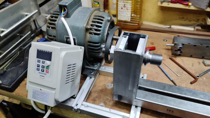
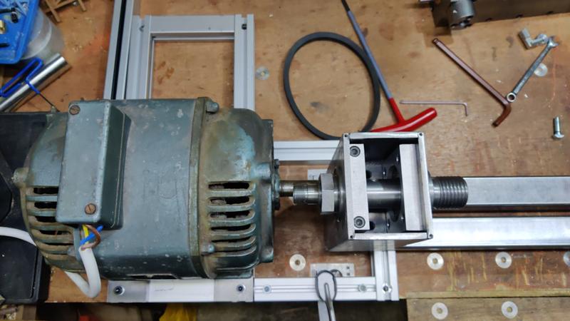
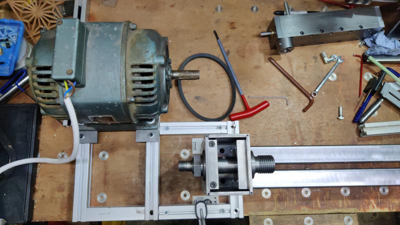
I wouldn’t, of course, know how but could you not do away with the belt and pulley and have a direct drive?
 
Lons":3so4bzrn said:
Al
Are you sure you haven't got half a dozen little helpers? Your progress is amazing. :eusa-think:

:lol:

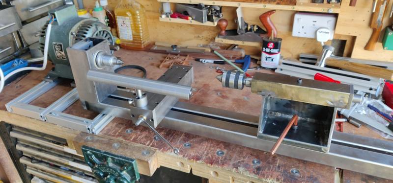
It's more spread out than it seems. The tool rest slide mechanism was done in amongst other jobs over the last couple of weeks. Yesterday was when I had a chance to video the operation & hence post the process, but the last piece was finished on Thursday evening.

All of yesterday afternoon was spent on the tool rest itself, but I wanted to get the post about the mechanism done, so I postponed posting about the tool rest until this morning. Today has just involved welding the end plates on, which is quite a quick job really.
 
Andyp":4z31mo9j said:
I wouldn’t, of course, know how but could you not do away with the belt and pulley and have a direct drive?
I guess it's possible (with a flexible coupling of some sort), but it puts some tight constraints on height alignment and also rules out the ability to change gear ratio with different pulleys, so I think I prefer the drive belt approach.
 
I've been carrying on working on the lathe and taking lots of photos, but I haven't been keeping up with writing it all up. I'll spread this weekend's work over a few posts rather than trying to cover it all in one go.

Another little job that I needed to do was make a T-nut for the tailstock. This will engage with the bottom of the bed and will be used to lock the tailstock in place. I possibly could have used a T-nut from the clamping kit from my milling machine, but I decided to make one a bit bigger and with a deeper upright section. If I decide in time to replace the bed (currently 40 mm × 40 mm × 2 mm box section) with something a bit stronger (e.g. 40 mm × 40 mm × 4 mm box section), it's likely that there will be a bigger fillet radius (box section outside fillet radius is typically 2×thickness) and hence the T-nut needs to extend beyond that fillet.

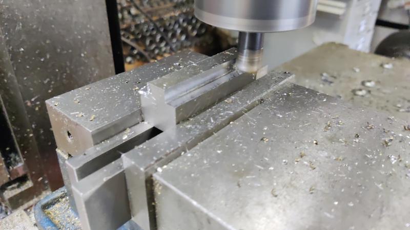
While I was at it, I decided to use the same "form factor" to make what is essentially a pair of washers for holding the headstock in place. I started with an offcut of 25 mm square EN1A and I used a little 16 mm carbide insert end mill (that I picked up at the Bristol Model Engineering Exhibition a few years ago) to mill the T shape:

t_nuts_01_milling_800.jpg


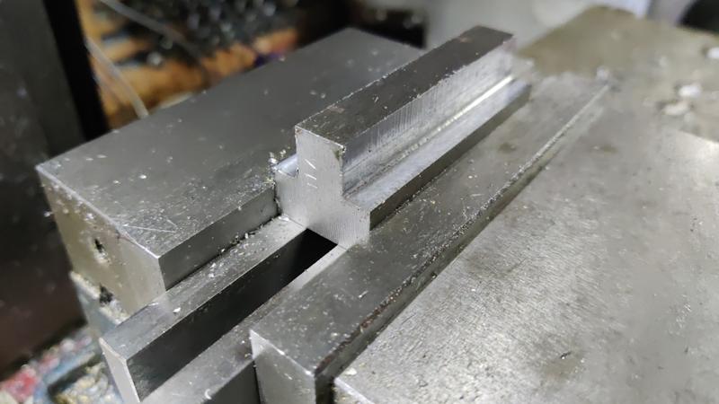
The upright bit is 12 mm tall, so should easily pass any fillet on a box section corner:

t_nuts_02_milled_800.jpg


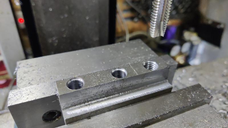
I then drilled three holes and tapped one of them:

t_nuts_03_drilled_and_tapped_800.jpg


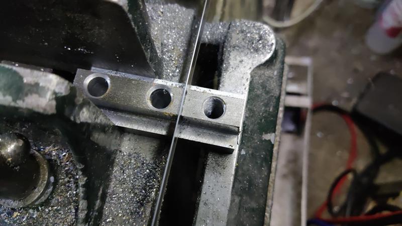
Finally, the t-nuts were split into two pieces:

t_nuts_04_splitting_800.jpg


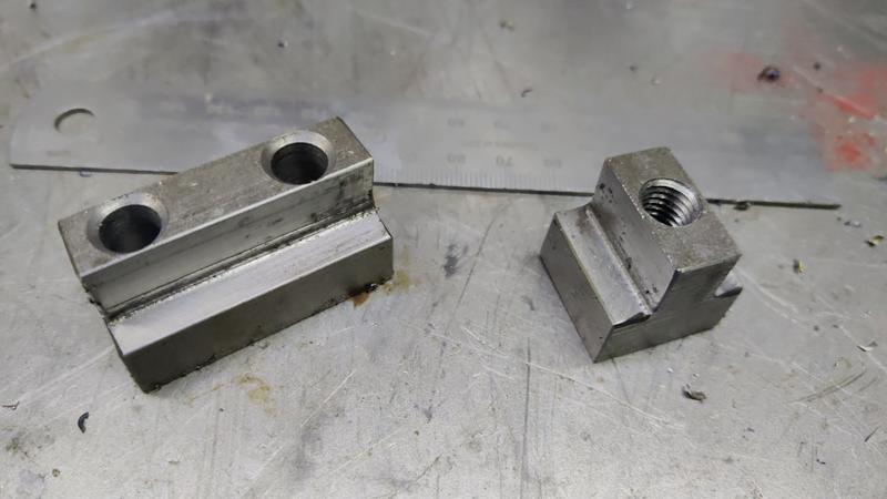
After a quick tidy up of the sharp corners, they're done:

t_nuts_05_done_800.jpg


The spacing of the two holes on the "washer" for the headstock matches the spacing of the M8 holes in the bottom of the headstock. If I'd made them as individual washers, they would have had to be rectangular (or have one side cut off) to stop them interfering with each other, but making a single washer sorts that problem out.

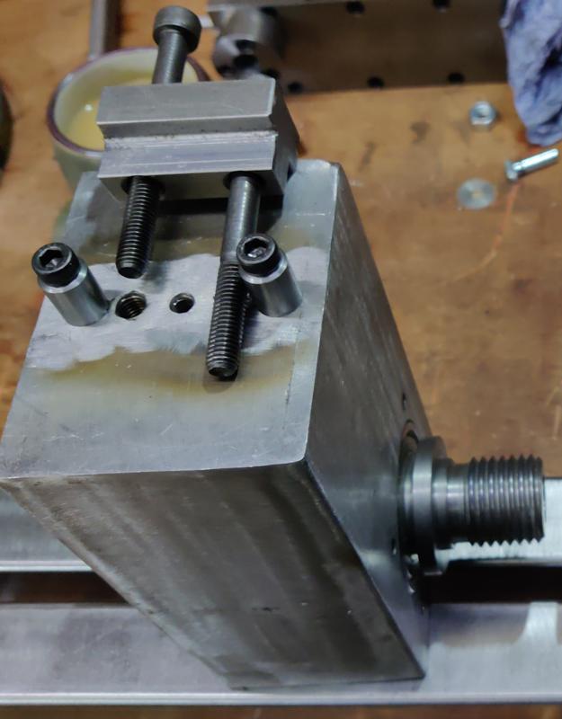
My original plan for aligning headstock and tailstock was to use some eccentric pins. After pondering for a bit, I decided to do this just for the tailstock: the headstock is likely to be pretty much permanent attached to the bed, so it doesn't really need to be as easy to adjust. To get it in roughly the right placed, I made a couple of 12 mm pins with 6 mm holes through the middle. These attach to two of the threaded holes in the base of the headstock and are a fairly tight fit in the bed slot:

0303_headstock_alignment_pins_800.jpg


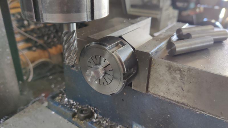
For the tailstock, I made four pins, each slightly under 12 mm. I used a collet block to mill a 10 mm AF hexagon on the end of each block:

0303_tailstock_alignment_pins_1_hex_800.jpg


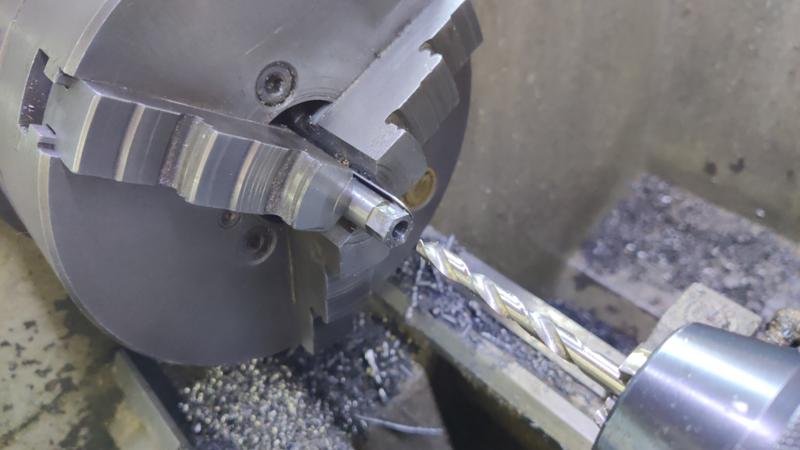
I then used a bit of feeler gauge stock against one of the chuck jaws to hold the pin off centre. I could then drill a 6 mm hole all the way through:

0303_tailstock_alignment_pins_2_off_centre_holes_800.jpg


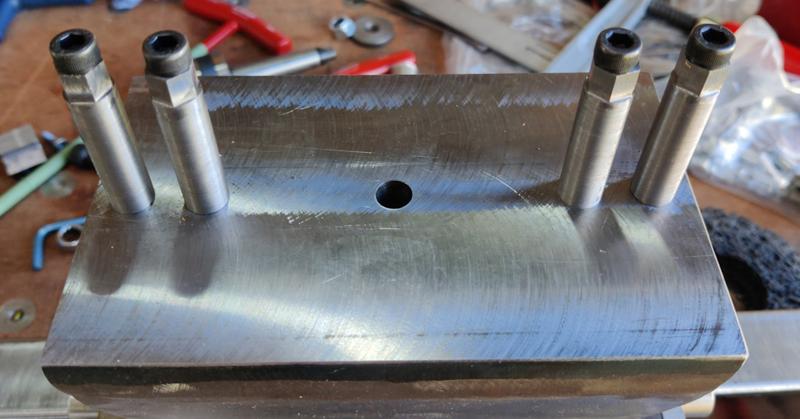
This shows the pins fitted to the base of the tailstock:

0303_tailstock_alignment_pins_3_fitted_800.jpg


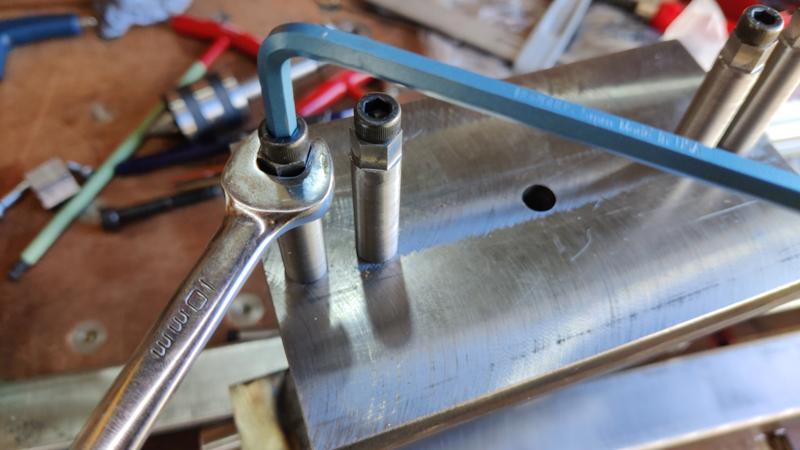
They can be adjusted with a 5 mm Allen key and a 10 mm spanner:

0303_tailstock_alignment_pins_4_adjustment_800.jpg


The length of the pins was chosen such that the hexagonal section sticks out beneath the base of the bed and hence they can be adjusted in situ.

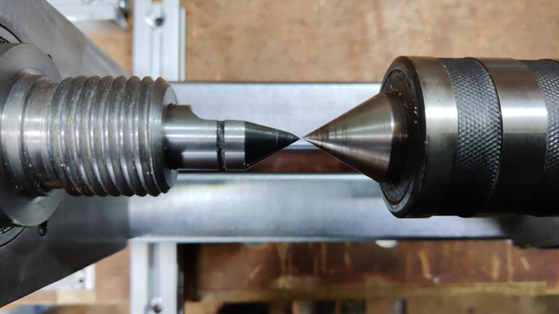
0303_bed_09_centres_800.jpg
 
You've completely and utterly lost me, Al. All I can say is that it looks like you know what you're doing. :D

Why would you need to drill an off-centre hole through a pin? (Asks Mike, who has no idea what the pins are for.....)
 
What strikes me as much as your skill is the ability to work through the project without detailed drawings. :eusa-clap:
i often work with very basic sketches or none at all but couldn't even contemplate it with something as complicated as yours. There would have been multiple disastrous mistakes made. :lol:
 
Mike G":39jtrfny said:
Why would you need to drill an off-centre hole through a pin? (Asks Mike, who has no idea what the pins are for.....)
If I'm reading it right - and I'm sure Al will correct me if I'm not - the 12mm pin is a snug fit between the two halves of the bed, and the 6mm slightly-offset hole has an M6 screw attaching it to the base of the tailstock. By loosening that screw and rotating the pins, he can effectively shim the tailstock to one side or another.
 
Mike G":2s2ijwfi said:
You've completely and utterly lost me, Al. All I can say is that it looks like you know what you're doing. :D

Why would you need to drill an off-centre hole through a pin? (Asks Mike, who has no idea what the pins are for.....)

I guess I didn't explain it very well, sorry.

As the holes through the pins are off centre, rotating the pins moves the centre of the pin. With two pins pushing against one side of the bed slot & two pins pushing against the other, the rotation causes the tailstock either to move side to side or to rotate. That adjustment allows me to line the tailstock up with the headstock.

Does that make sense?
 
It does, thanks.......but it raises other questions. Why not just machine everything perfectly straight and with no tolerance, such that you don't need adjustment?
 
Mike G":1o7t4zbx said:
It does, thanks.......but it raises other questions. Why not just machine everything perfectly straight and with no tolerance, such that you don't need adjustment?

Because that's difficult! Anything welded moves when you weld it, and sometimes moves when you machine it after welding it. Also, there's only so much accuracy you can achieve when lining stuff up on a little bench top Chinese milling machine.

At the end of the day, adjustability is just easier than precision.
 
The next job to work on was the method of attaching the bed to the motor.

I've got quite a lot of 3030 t-slot extrusion. A lot of it has holes/slots in various places (most of it came out of a skip having been used and discarded), but it's still perfectly usable. This seemed a good basis for the motor mount as the t-slots give an easy method of sliding the motor back and forth to apply tension to the belt.

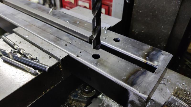
To attach to the bed, I clamped the bed in the mill vice (with some 12 mm flat bar in the gap to stop the vice from bending the bed) and drilled some holes:

0303_bed_01_rivnut_holes_800.jpg


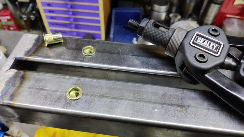
Rather than welding in some nuts (and risking distortion from the heat of welding), I decided to use M8 rivnuts for the bed attachment. These also have the advantage of being very quick to fit:

0303_bed_02_rivnuts_800.jpg


Some "feet" could be attached to the bed using those rivnuts:

0303_bed_03_feet_800.jpg


There's one of these at each end of the bed. They raise the bed up by 30 mm, giving clearance for the t-nuts etc. I've spaced them 864 mm apart and drilled / counterbored some extra 8 mm holes out-board of the bed on a 192 mm pitch. Those numbers are both multiples of 96 mm, which corresponds with the dog hole pitch on my bench, so I have the option of screwing the bed down using those holes (although in practice I suspect it will be quicker to just use a couple of F-clamps).

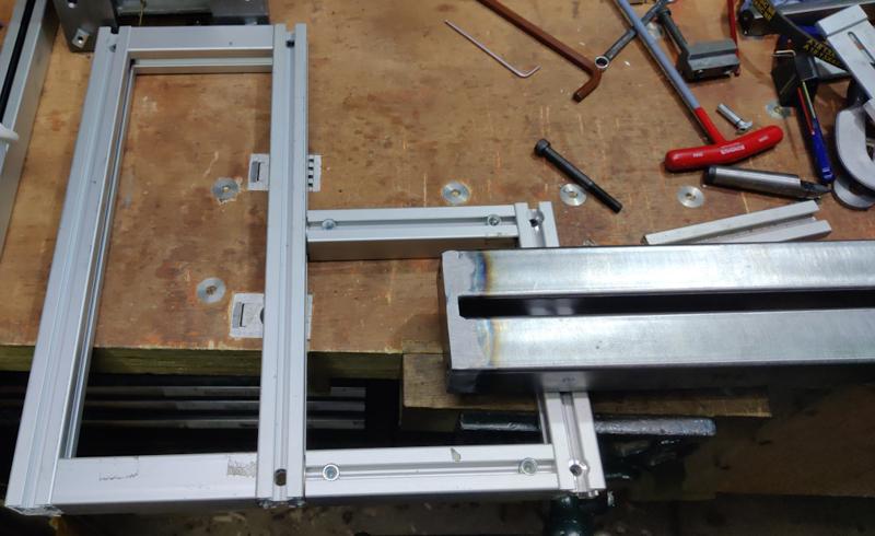
I then built a simple frame out of t-slot extrusion, using some coupling joints that came out of the skip with the extrusion:

0303_bed_04_frame_800.jpg


By undoing two of the M8 grub screws that hold the frame together, the motor mount section can be easily separated from the bed section, which is important as I don't think I'd be strong enough to lift the lathe and motor in one piece (the motor is very heavy).

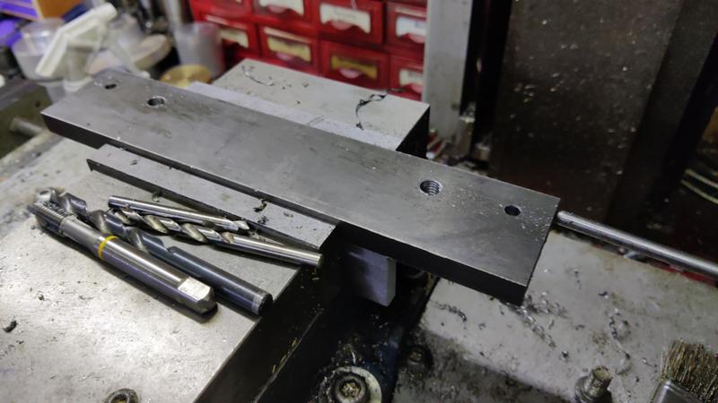
To attach the motor to the extrusion, I cut a couple of lengths of 12 mm × 50 mm EN3B and used the lathe to drill/tap a couple of M10 holes and drill a couple of 6 mm holes in each:

0303_bed_05_motor_plates_800.jpg


Those plates got bolted to the bottom of the motor with some short M10 cap screws and some extrusion t-nuts and M6 cap screws used to hold the motor mount plates to the extrusion:

0303_bed_06_motor_fitted_800.jpg


Loosening the four M6 cap screws allows the motor to slide easily back and forth on the relatively smooth surface of the aluminium extrusion. The two extremes of travel are shown in the next two photos:

0303_bed_07_motor_travel_extreme_1_800.jpg


0303_bed_08_motor_travel_extreme_2_800.jpg


General view of everything:

0303_fitted_to_bed_800.jpg


With that done, I thought I'd have a go at making some pulleys (and reminding myself why I hate turning aluminium). I had thought about modifying the spindle such that the pulley mount diameter was common between the motor and the spindle, but after thinking about it more I decided not to do this. The pulley for the motor probably needs to be longer (thicker?) than the one for the spindle due to the different mounting methods. The spindle pulley will be held on using a nut; the motor has a keyway and no thread, so the pulley is best mounted with a grub screw.

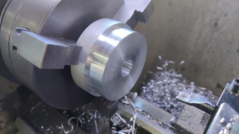
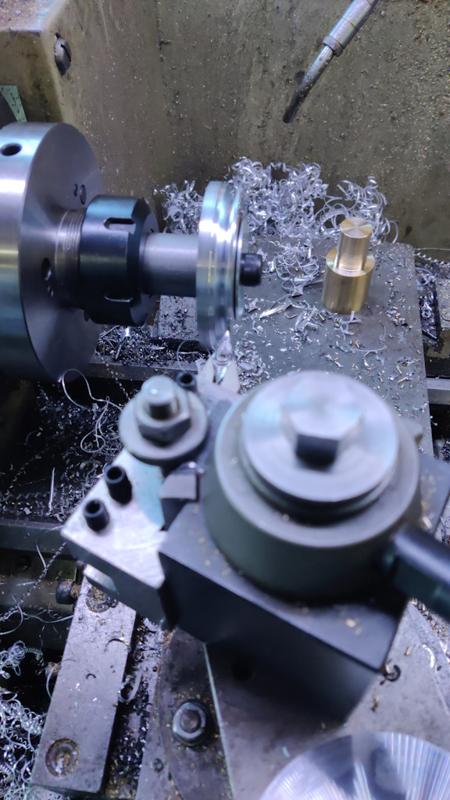
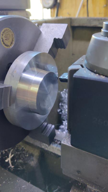
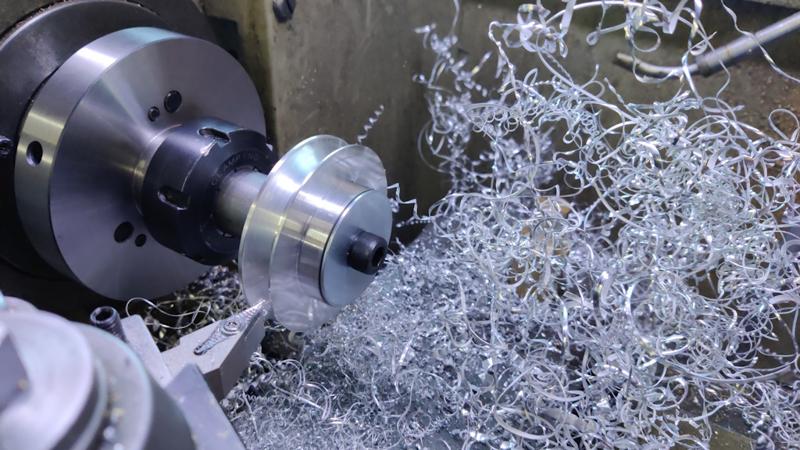
For the spindle pulley, I started with a big disk of aluminium, held in the outside jaws of the three-jaw chuck. I faced the end, skimmed the outside diameter down to 80 mm (fairly arbitrarily chosen) and drilled/bored a 20 mm hole through the middle:

0303_pulley_spindle_1_shaping_800.jpg


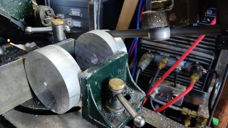
I used the bandsaw to chop it off over length:

0303_pulley_spindle_2_sawing_800.jpg


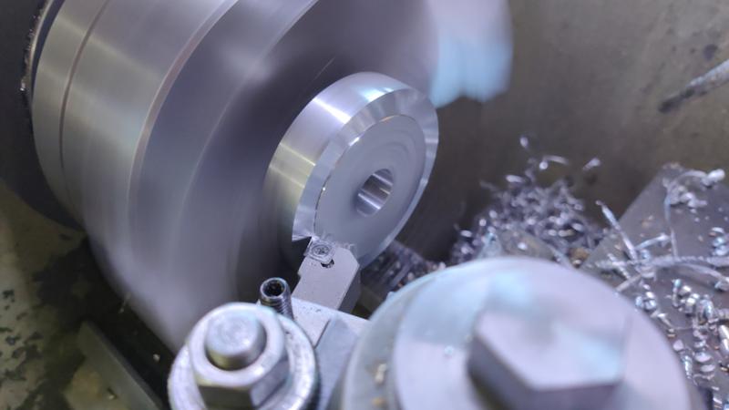
I then faced it to length, again held in the outside jaws:

0303_pulley_spindle_3_facing_800.jpg


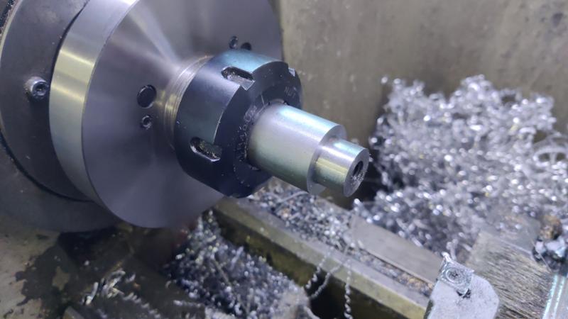
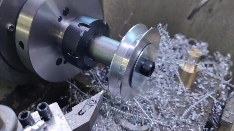
To help with shaping the pulley, I used a bit of 30 mm EN1A to make a simple mandrel, with a 20 mm outside diameter and an M10 hole through the middle. I used the collet chuck to hold the mandrel as it gives a bit more clearance for top slide rotation (and to remove the chance of accidentally hitting the spinning jaws).

0303_pulley_spindle_4_mandrel_800.jpg


I then set the top slide at 70° to the lathe axis to cut one side of the pulley shape (the drive belt I have has a 40° included angle, so 20° on each side). I then rotated the top slide and did the same for the other side of the pulley shape. I tried to get a few photos, but messed up the focus on all of them; believe it or not, this was the best:

0303_pulley_spindle_5_blurry_cutting_taper_800.jpg


This was what it looked like when finished:

0303_pulley_spindle_6_shaped_800.jpg


To make the motor pulley, I started with another disk of aluminium and turned a reduced diameter section (about 50 mm). This section is intended to be where the grub screw will be fitted for clamping the pulley onto the motor shaft.

Due to the overhang of the outside lathe jaws, there wasn't space for a normal tool, so I used a boring bar and turned the shape with the lathe running in reverse:

0303_pulley_motor_1_reverse_turning_800.jpg


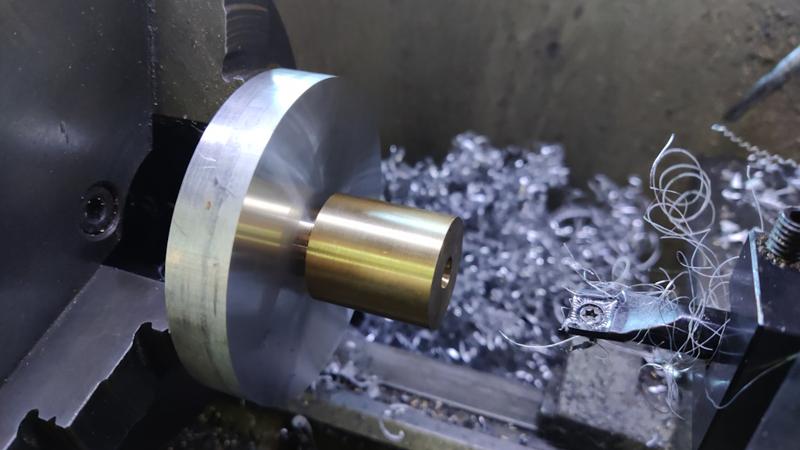
I then bored the 19.05 mm (3/4") diameter hole in the centre, using a bit of brass (that I'd previously turned to size) to check the size was (what I thought was) right:

0303_pulley_motor_2_bored_to_size_800.jpg


The same mandrel as before (but turned for a longer section at a smaller diameter) was used to mount the blank and I could then turn the pulley shape. This photo gives more of an idea of why I detest turning aluminium!

0303_pulley_motor_3_cut_with_ratsnest_800.jpg


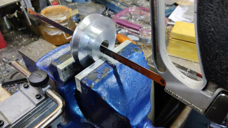
To cut the keyway, I started by feeding a hacksaw blade through the slot and then remounting it to the hacksaw frame. I could then rough out the slot:

0303_pulley_motor_4_hacksaw_800.jpg


That got finished with a lot of tedious work with a hand file.

I then had a go at fitting the pulleys. The spindle one went on very easily and was clamped in place with another nut that I made in the same way as the spindle mount nut that I described earlier (I also shortened the spindle mount nut and made a second short one as they're now being used to pre-tension the spindle bearings and hence need to lock together to hold the tension).

The motor pulley was a lot more involved. I'd measured the motor spindle near the bearing and it was 19.048 mm according to my micrometer. That corresponds fairly closely to 19.05 mm, which is 3/4", so that made sense to me and hence that's the size I made the pulley bore. When I tried to fit the pulley, it wouldn't go on.

I re-measured the motor spindle and found that (rather bizarrely in my opinion), it's 19.048 mm near the bearing, but 19.35 mm at the tip! That makes for a rather awkward situation: if I enlarge the hole to be 19.35 mm, then it might end up being very loose by the time it's pushed all the way on (although I guess the grub screw would probably deal with that issue).

I've got a 19–21 mm adjustable reamer, so I used that to gradually increase the bore diameter. I was feeling quite nervous about making it too big (I really didn't want to have to start again with this part!), so I took very light cuts and kept trying to mount it on the motor spindle. After several cuts, I found that I could "persuade" the pulley onto the motor shaft with a mallet.

It took quite a bit of persuasion to get it to seat. Sufficient persuasion that it'll need a bearing pulley to get it back off! I had intended to cross-drill and tap the hole for the grub screw after making sure that the pulley fitted over the keyway, but given how tight it is, I've decided to leave it for now.

With an 80 mm (outside) diameter motor pulley, it should be easy enough to adjust speed (if I need more range than I can get from the variable speed drive) by either fitting a bigger spindle pulley (for slower speeds and more torque) or a smaller one (for higher speeds). I'm not sure which diameter to use for the speed ratio calculation (outside of the belt, inside of the belt, middle of the belt?), but with the variable speed drive, it probably isn't that critical.

For now, I've got 80 mm outside diameter pulleys on both the motor and the spindle, so the speeds should match.

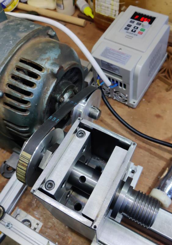
With the pulleys made and fitted, I could fit the drive belt and slide the motor back to apply some belt tension:

0303_pulleys_fitted_800.jpg


I couldn't resist a quick spin test:

[youtubessl]ciBldQEHoZU[/youtubessl]

It's feeling much closer to being a lathe now that the spindle has been run, but there are still quite a lot of pieces to make before I can start cutting wood. My hope is that I'll be able to at least do some trial cuts by the end of next weekend, but we'll see what happens.
 
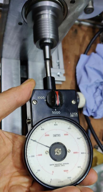
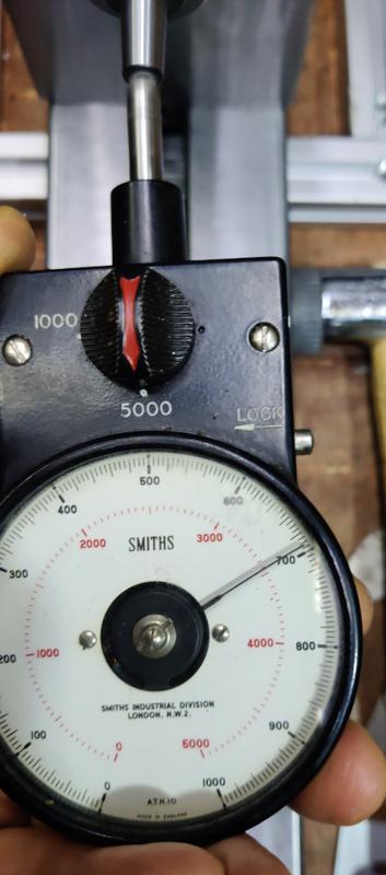
I didn't have much free time this evening (and most of what I did have was spent clearing up aluminium swarf), but I did manage to rummage out my old speed gauge and used it (along with the centre pip in an MT2 drill chuck arbor) to find out what the spindle speed was with the variable speed drive set to 50 Hz:

0403_01_50hz_800.jpg


Looks like 1500 rpm to me. I also decided to live dangerously and wind the drive frequency up to 120 Hz. Nothing sounded odd (which was nice!) and the speed read-out shows 3450 rpm:

0403_02_120hz_800.jpg


That's not far off linear given the resolution of the gauge. I'm sure it'll slow down a bit when under load (i.e. doing some actual turning) and I'm sure the slip will be greater at the higher frequency, but it does suggest that it might be usable over a decent speed range.

The drive has a nice feature where you can programme in the RPM you get at 50 Hz and then set the display up to show how fast the lathe is running at any frequency. I doubt it's doing anything very intelligent to account for loading, but it might still be a handy guide when I'm aiming for an approximate speed.
 
Hi Al
Can I ask what is probably a silly question re the motor spindle?
Faced with that size issue my immediate thought would be to spin the motor and use a fine file / abrasive on the spindle rather than work on the pulley. Would that have worked?
 
Lons":mx06er5n said:
Hi Al
Can I ask what is probably a silly question re the motor spindle?
Faced with that size issue my immediate thought would be to spin the motor and use a fine file / abrasive on the spindle rather than work on the pulley. Would that have worked?

Not a silly question at all. It would have worked well, if and only if I could have removed the key. I'm not sure how the key is held into the keyway slot (possibly just corrosion), but I couldn't shift it.
 
Dr.Al":3ehkyuya said:
Lons":3ehkyuya said:
Hi Al
Can I ask what is probably a silly question re the motor spindle?
Faced with that size issue my immediate thought would be to spin the motor and use a fine file / abrasive on the spindle rather than work on the pulley. Would that have worked?

Not a silly question at all. It would have worked well, if and only if I could have removed the key. I'm not sure how the key is held into the keyway slot (possibly just corrosion), but I couldn't shift it.
That makes sense
 
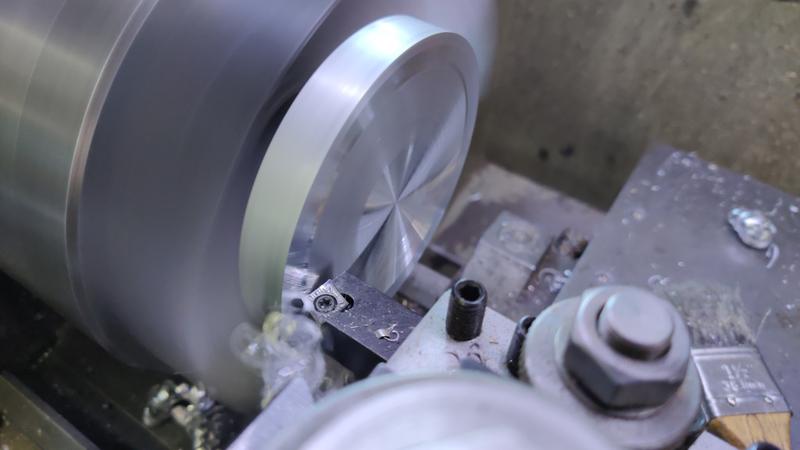
I had a couple of hours free this evening, so I thought I'd get on with another aluminium turning job. I think this is the last one and there isn't much material to remove, so it's not as unpleasant as making the pulleys.

I started with another bit of skip-dive aluminium. I mounted it in the three-jaw chuck and faced one side:

0603_handwheel_01_facing_aluminium_800.jpg


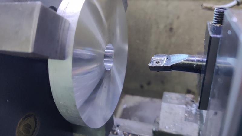
I then flipped it round, faced the other side and then drilled and bored a hole in the middle. I crept up on the final dimension, testing with the tailstock screw repeatedly until it went on with a snug fit.

0603_handwheel_02_flipped_faced_and_bored_800.jpg


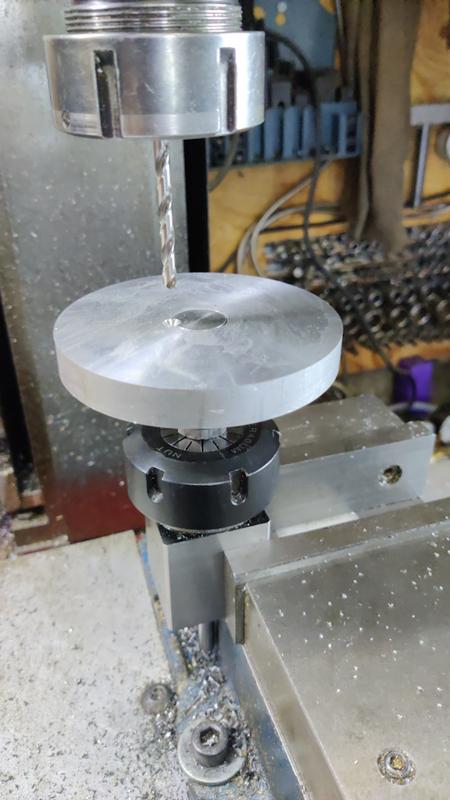
With that done, I took the aluminium piece off the lathe and pushed it onto the tailstock screw, with a bit of superglue applied to hold it (temporarily) in place. The assembly could then be mounted in a collet chuck on the milling machine and a hole located right on the join between the two parts:

0603_handwheel_03_spot_drilled_800.jpg


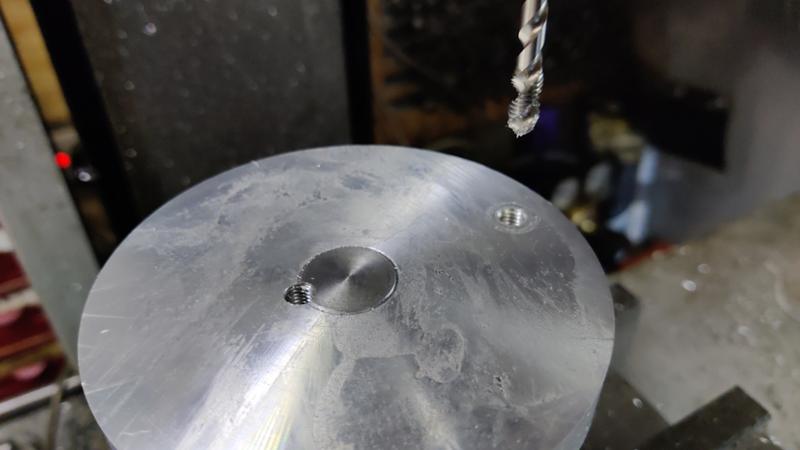
That hole (shown after spot drilling above) was then drilled 5 mm to a depth slightly less than the thickness of the aluminium disk and then it was tapped. A through hole was also drilled and tapped in a fairly arbitrary location near the rim:

0603_handwheel_04_tapped_800.jpg


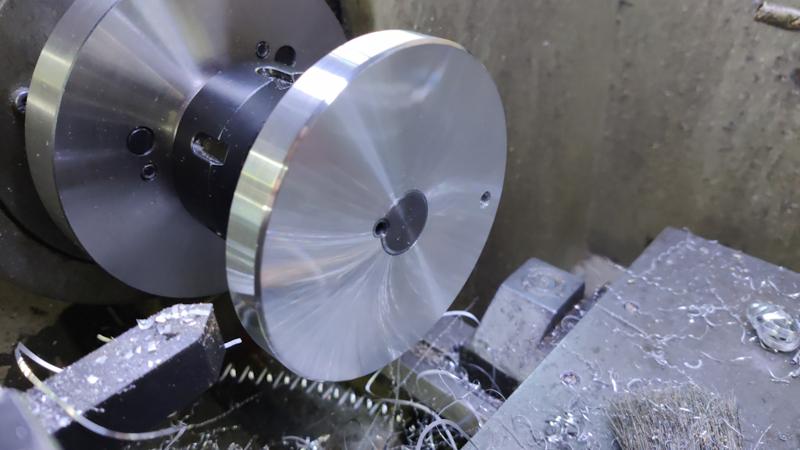
With that done, a grub screw was tightened into the joining hole and the whole assembly put back on the lathe for a final light skim of the face (the facing cut was mainly to remove the superglue stains to be honest). The outside edge was also cut and some chamfers cut and the edges broken with a fine file:

0603_handwheel_05_grub_screw_in_faced_and_shaped_800.jpg


The assembly was then stood upright in the bench vice and acetone poured over it to weaken the superglue so that the parts could be separated (the bearing retaining plate needs to go between the aluminium disk and the bearing so the parts can't be glued together).

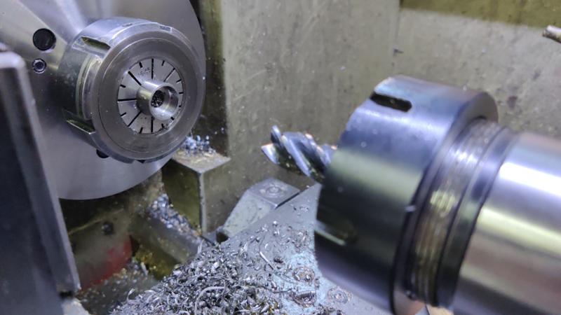
I dug out a bit of 16 mm 303 stainless steel and held it in the collet chuck (the main reason I used the collet chuck was that it was already fitted to the lathe). I drilled a 7.6 mm hole all the way through, then reamed it out to 8 mm. I then used a 14 mm end mill to cut a shallow counterbore:

0603_handwheel_06_drilled_reamed_and_end_milled_800.jpg


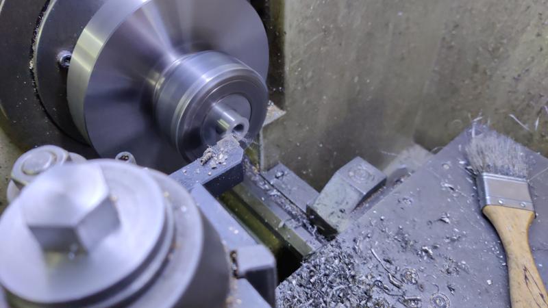
The part was then reversed in the chuck and faced to length, removing it and checking the length several times to get it just right.

0603_handwheel_07_facing_to_length_800.jpg


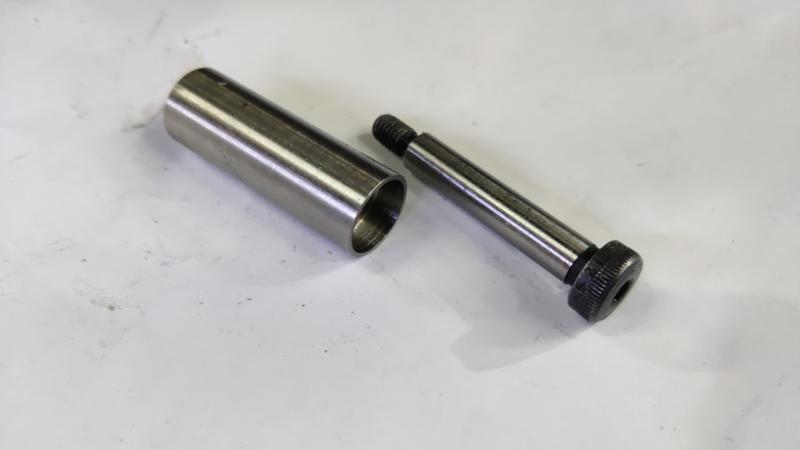
Here's the finished stainless steel handle, along with a shoulder screw that will be used to hold it in place. The shoulder of the shoulder screw is very slightly longer than the 8 mm diameter section of the stainless steel handle, so when tightened into the aluminium disk, the stainless handle spins freely:

0603_handwheel_08_with_shoulder_screw_800.jpg


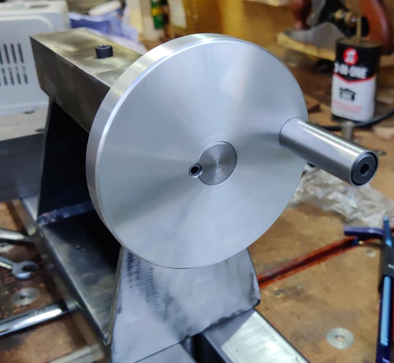
With that done, I could call the tailstock handwheel complete and fit it to the tailstock:

0603_handwheel_09_all_done_800.jpg
 
This thing is going to be better built than most branded wood turning lathes.
 
Nearly there. :eusa-dance:

It might be worth making a face plate to fit on to the thread of the spindle shaft Al. they can be very useful at times, and a pen mandrel and loads of other additions, it's a deep hole. :lol:
 
Thanks all for the comments

Lons":13tqlqoh said:
Nearly there. :eusa-dance:

Definitely getting closer, but there are still quite a lot (about 24 I think) more pieces to make

Lons":13tqlqoh said:
It might be worth making a face plate to fit on to the thread of the spindle shaft Al. they can be very useful at times, and a pen mandrel and loads of other additions, it's a deep hole. :lol:

There's a reason I made the spindle thread a standard one: I think I'll buy those bits. I'm going to try to make enough that I can turn something simple (a chisel handle), but then I'll probably do some shopping! Rather conveniently, we've got a weekend away in Lyme Regis booked in a couple of weeks' time and that will be very convenient for popping in to Axminster and Yandles (and Dolphin Antiques, and the Vintage Trading Post...) :)

I might take the spindle along with me so I can check that the M33×3.5 thread actually fits the headstock accessories, although I'm not sure whether I'll be able to do anything about it if it doesn't :? .
 
Actually when I come to think about it, I am surprised by how much work goes into making a DIY wood lathe. In my case I only do turning where necessary, and although the course I did at Axminster had lovely big speed controlled lathes, mine at home is a second had Record CL something where you have to shift a belt over (which I hardly ever do). It's basically a rudimentary heavy metal floor stand, two big round solid bars for a bed, a motor at one end and a pointy bit at the other end. The rests are really quite basic. It will do bowls, vases, spindles and wooden pot lids etc quite happily. Only gave £100 for it from a very nice chap on UKW. I did buy a chuck from Ax and that is by far the most complicated bit of engineering on the lathe.

I think yours will do pretty much everything you need Al unless you get into very complex turning. And with your penchant for precision, that is entirely possible :lol:
 
Even I managed to make a faceplate for my last lathe Al so it must be easy and for someone with your set up and skill it's a doddle. A 100mm or 150mm steel plate is around £30 - £40. I'd be saying "HOW MUCH?"

Am I right in thinking that once it's finished and you've turned a few things you'll lose interest a bit and look for another project? I'd suspect most of the enjoyment and satisfaction comes from making the machine and solving the problems, or am I barking up the wrong tree. ;)

I have the Axi SK100 chuck and a number of additional jaws, same thead as yours and I've found it to be accurate and versatile though I think there were a few that were less accurate so check the chucks carefully whatever you go for.
 
AJB Temple":26pluvuj said:
Actually when I come to think about it, I am surprised by how much work goes into making a DIY wood lathe. In my case I only do turning where necessary, and although the course I did at Axminster had lovely big speed controlled lathes, mine at home is a second had Record CL something where you have to shift a belt over (which I hardly ever do). It's basically a rudimentary heavy metal floor stand, two big round solid bars for a bed, a motor at one end and a pointy bit at the other end. The rests are really quite basic. It will do bowls, vases, spindles and wooden pot lids etc quite happily. Only gave £100 for it from a very nice chap on UKW. I did buy a chuck from Ax and that is by far the most complicated bit of engineering on the lathe.

I think yours will do pretty much everything you need Al unless you get into very complex turning. And with your penchant for precision, that is entirely possible :lol:

I'm sure mine is overdesigned in some ways (and possibly underengineered in others - in particular the bed strength and the tool rest shaft size). No doubt I could have bought one that would have done everything I needed (and if I had any sense, I would have done so :D ). It's been an interesting project though: definitely the most challenging metalwork project I've ever done and it's good to stretch myself.

Lons":26pluvuj said:
Even I managed to make a faceplate for my last lathe Al so it must be easy and for someone with your set up and skill it's a doddle. A 100mm or 150mm steel plate is around £30 - £40. I'd be saying "HOW MUCH?"

I'm sure I could make one, but faceplates don't seem that expensive to buy. I've found 75 mm ones online for £15 and 150 mm ones for £31 without very much shopping around. I'd be surprised if I could buy a length of 150 mm steel for that price and then I'd have to make an internal threading tool for the 3.5 mm pitch thread and have all the hassle of making an internal thread. For £15-30 I think I'll just buy one if/when I need one.

I think of faceplates as being something that is used a lot for bowl turning (which doesn't really interest me), although I'll be the first to admit that I don't know what I'm talking about :)

Lons":26pluvuj said:
Am I right in thinking that once it's finished and you've turned a few things you'll lose interest a bit and look for another project? I'd suspect most of the enjoyment and satisfaction comes from making the machine and solving the problems, or am I barking up the wrong tree. ;)

I think that's quite likely. I do rather enjoy designing and making tools (partly as I then get to use them to make more tools ;) ). Making turned "products" (bowls, pens etc) doesn't greatly interest me. I'm sure the lathe will get used quite a bit for tool handles and later for things like drawer pulls, but there aren't many things that come to mind that I can see myself making. Never say never of course.
 
I'm with you on this Dr Al.

I know people enjoy making pens but I doubt many get used much these days. You make a few bowls and it's quite good fun learning the lathe. Then everyone in your circle has a bowl - and that's bowls done forever. Axminster on their course teach you how to make a mushroom thing. I made exactly two. Plus two vases. And a bowl. The only reason I got a dirt cheap lathe and learnt how to use the tools safely, was to make newel caps and spindles to repair a staircase which had custom turnings. It has been used to make a couple of light spacers and a lid for a ceramic bread jar and a few bits and bobs for friends who asked for them, but it is a bit of a green elephant otherwise. Thought I would use it more than I have. :?
 
AJB Temple":126v2uhf said:
I know people enjoy making pens but I doubt many get used much these days.

Completely the wrong assumption.

There are a lot of turners making pens and selling them, some of whom I've known for years both in person and on line. several selling for specific charity raise large sums and others are making decent money from them and I'm talking from actually experience not just voicing unsubstantiated opinion.

A friend of mine has a healthy business supplying kits and blanks and has done so for years, I don't make many personally these days but only because I have other things to do and I don't need the money but when I got my first lathe I made enough profit in a couple of months to pay for that and buy a second larger lathe which I still have. You would be surprised how many fountain pens are sold as well as special occasion instruments for weddings etc.
 
Damning by faint praise?

It really isn't difficult to verify Bob's point. For example, Andy Pickard (good buddy of one Woodbloke52) helped start a movement when he made some pens from H.M.S. Victory's original timber wood (that was replaced by conservatorship). There is now a lucrative market in nostalgia-related 'pennery' out there:

https://www.etsy.com/uk/listing/1070736 ... wgQAvD_BwE

It just takes someone to throw off the blinkers and apply lateral thinking. Also, tastes differ; I can't stand opera, but some musician friends threaten to disown me when I say so.

Heigh Ho, they also like Heineken :shock: .

Edit: Sorry for the diverticulum Al; pray go on, still fascinating.
 
AJB Temple":mdez404s said:
I expect you are right Bob.

Yep. ;)

I have a friend in York who makes his living these days teaching woodturning but worked for the Joseph Rountree school when we first met and I attended the first of his fundraising days, one of the guys since has started a thriving retail business in Yorkshire based mostly on pen turning supplies, he has a stand at Harrogate and other shows while the local friend I mentioned earlier who's business is well established is mainly internet based. Two of the others have been making thousands of pens and auctioning them in aid of Help for Heros, unfortunately one of them, Terry has recently died but my other friend is still going strong.

There's a thriving if relatively small industry in existence and there's clearly still a market for good old fashioned writing instruments in addition to key tapping and touchscreens. I still sell a few but only when I get specific requests, they make great presents.
 
There was no praise & no damning Sam. Don't take things too seriously! Everyone has a view (or couldn't care less) and no doubt there's a niche. It's a generation thing. Schools use pens as do some people brought up in the pen age. Outside of that for people under 30, pennery almost totally replaced by phonery, apps & voice recognition (Siri, Alexa etc). Penxtinction lies ahead as the pen drawer slowly becomes the pen grave :D
 
Exactly Bob. It's a niche and we agree. I still have my fountain pens and bottles of ink. I try to use them when I sign cards about 8 times a year, for old times sake. But if I need a pen it is usually a sharpie for marking on walls or a cheap uni eye at 3 as these have excellent fine lines. :oops:
 
Over on the other site a chap has got quite a nice lathe for sale. Big and heavy Axminster speed controlled one. I think the same as they used on the turning courses, although they also had Jet as well, which was nicer.
 
Ohh, but I do you see. Probably ingrained from years of out-witting the devious and wily - pupils and parents.

Methinks we should consult A.L.F. for a a judgement on the demise of Parkers et al. I believe that, when she took a sabbatical from creative ways of generating sawdust, she embraced Caligraphy and became a Stylophile par excellence.
 
AJB Temple":q3iq29yj said:
It's a generation thing. Schools use pens as do some people brought up in the pen age. Outside of that for people under 30, pennery almost totally replaced by phonery, apps & voice recognition (Siri, Alexa etc). Penxtinction lies ahead as the pen drawer slowly becomes the pen grave :D

Well as we all know stats and surveys can be made to justify anything but I don't entirely agree with you and neither do some of the organisations albeit with vested interest who do research and surveys. here's a snippet from one for example.
Remember use includes jotting down reminder notes, entries on callendars and using pens and pencils in the workshop. Sitting behind a desk on the phone you're also far more likely to jot down shorthand notes on to paper than an ipad or laptop either unless your in a service dept or call centre.

Using computers, smartphones and laptops as part of our daily lives means people can now swap their pen for keyboards or touchscreens if they choose to. But the Pen Heaven survey found that most people still write by hand every day, suggesting the majority still see the value in putting pen to paper. Out of those who took part in the survey, 51.4% wrote by hand on a daily basis, while 21.4% picked up a pen to write at least once a week. However, on the other end of the spectrum, 16.5% of people admitted they couldn’t remember the last time they wrote something by hand. Men write less regularly than women with 19.4% saying they were unable to remember the last time they wrote by hand compared with 13.5% of women. Many people assume the older generation places a higher value on handwriting than younger people who may be more likely to use gadgets to communicate instead. But the Pen Heaven poll indicates this isn’t the case at all. Just 39.5% of over-65s wrote by hand every day while 18-24-year-olds were the most likely age group to pick up a pen with 60% saying they used a pen or pencil to write daily. At Pen Heaven we have previously discussed the memory benefits of writing regularly.
Using a Notebook is still very Popular
Pen Heaven also asked participants whether they used a notebook to jot down their thoughts, ideas and reminders. The results proved that scribbling down notes was still a popular way to stay organised with 28.8% saying they used a notebook on a daily basis, and 28% at least once a week.
 
Back
Top