• Hi all and welcome to TheWoodHaven2 brought into the 21st Century, kicking and screaming! We all have Alasdair to thank for the vast bulk of the heavy lifting to get us here, no more so than me because he's taken away a huge burden of responsibility from my shoulders and brought us to this new shiny home, with all your previous content (hopefully) still intact! Please peruse and feed back. There is still plenty to do, like changing the colour scheme, adding the banner graphic, tweaking the odd setting here and there so I have added a new thread in the 'Technical Issues, Bugs and Feature Requests' forum for you to add any issues you find, any missing settings or just anything you'd like to see added/removed from the feature set that Xenforo offers. We will get to everything over the coming weeks so please be patient, but add anything at all to the thread I mention above and we promise to get to them over the next few days/weeks/months. In the meantime, please enjoy!

Electrical mystery (DC). Can you help?

Mike G

Petrified Pine
Joined
Jul 30, 2014
Messages
12,710
Reaction score
3,470
Location
Suffolk
Name
Mike
I am just finishing off the wiring of my teardrop, and the very last issue has me absolutely flummoxed. The kitchen light won't work. I have 13.5 volts at the buzz bars, and 13.5 volts at the connection to the light......but the light won't work. Obviously a faulty light.......

No! Put the light wires across the buzz bars and the light works beautifully. So, faulty connections, perhaps? I'm using Wago connectors, so I swapped them, and it made no difference. I tried the +ve from the supply and the +ve from the light in the same terminal, and the same with the negative in another connector. Still doesn't work. I tried just winding the wires together.......no joy. At a suggestion from a friend of mine, I measured the voltage at that connection when the light was wired up (and should be working). The voltage dropped from 13.5 volts to 1.5/ 2 volts (it fluctuated a bit) when I switched the switch to on.

I went through all that all over again with a spare (identical) light, with precisely the same results.

I have two of these lights wired up on another circuit, with no issues at all.

Can anyone shed any light for me, because the damn fittings obviously can't!! :)
 
It's hard to diagnose these sorts of things remotely, but it sounds like you have a very high resistance connection between buzz bars and light connection (e.g. some very thin and not very conductive wire). When you measure the voltage at the light connection, there's no current flowing, so the volt-drop across the cable (V = I×R with very small I) is low. As soon as you connect the light, current starts to flow and the volt drop gets big.

Can you use a multimeter and measure the resistance of the connection between buzz bar and light? If so you might be able to narrow down where the high resistance element is.
 
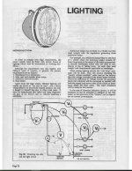
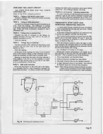
This may help @Mike G , I used to do old car electrics years ago and have copies of the old Lucas manuals, this is the part about fault finding on lighting circuits using the “Volt drop method”, as @Dr.Al outlined looks like a resistance issue:

Had to snap shot the PDF as it was too big a file:

Lucas 1.png
Lucas 2.png
 
Oh that's great chaps, thanks. I thought it was likely to do with eye of newt, leg of toad, or because I'd failed to sacrifice a virgin on the full moon.......

Let's see if we can narrow this down a bit more. I'm using the same 1.5 sq mm wire as per the other lighting circuits, and this circuit is somewhat shorter. The thinnest wire on the circuit is the stuff connected to the light by the manufacturer. On the other lighting circuits I have cut that bit down to 2 or 3 inches, but because it suits the location better in the kitchen I have left it about300mm long.......nonetheless, it works perfectly well when held to the buzz bars.

Is there any good way of testing if this is the issue?
 
Is the switch proven to be OK?
Well, it works, in that the voltage at the end of the circuit is 0 before it's switched on and 13.5 afterwards.....but I have others, and can easily swap them over tomorrow to see if it makes a difference.
 
......Can you use a multimeter

Barely!

and measure the resistance of the connection between buzz bar and light?

The cables on my multimeter aren't long enough to get anywhere close. Extending them with a scrap of spare wire would add another variable into the mix. Do you have a suggestion as to how to make this test work in practice?
 
Barely!


The cables on my multimeter aren't long enough to get anywhere close. Extending them with a scrap of spare wire would add another variable into the mix. Do you have a suggestion as to how to make this test work in practice?
Can you use a bit of chunky mains cable as the extension? Whatever you use, measure the resistance of the extension & then you can subtract that off whatever you measure with the extension in place.
 
Can you use a bit of chunky mains cable as the extension? Whatever you use, measure the resistance of the extension & then you can subtract that off whatever you measure with the extension in place.
Yes, I can do that. I've got some offcuts of 16 sq mm cable (the same size as jump leads). I'll cobble something together tomorrow.
 
Well, it works, in that the voltage at the end of the circuit is 0 before it's switched on and 13.5 afterwards.....but I have others, and can easily swap them over tomorrow to see if it makes a difference.
When you measured it, did you have the rest of the circuit connected? Light etc? I am guessing that perhaps not. My money is on the switch
 
At a suggestion from a friend of mine, I measured the voltage at that connection when the light was wired up (and should be working). The voltage dropped from 13.5 volts to 1.5/ 2 volts (it fluctuated a bit) when I switched the switch to on.

That is confusing. Not sure what 'that connection' is but the voltage was there when the switch was off (?) and dropped to 2V when it was on?

Assuming that's just typing problems and the basic circuit is correct it must be a bad connection. As said it could be the switch or it could be any of the connectors you have used. It could even be a bad bit of wire with a break somewhere inside it or a dodgy fuse. Use a length of single cable and bypass some of the joints and cables in the + wiring and then in the - wiring if needed. If it starts working you have narrowed down where to look for the fault.
 
When you measured it, did you have the rest of the circuit connected? Light etc? I am guessing that perhaps not. My money is on the switch
No, it was at the bare wires where they would join the light's wire.
 
That is confusing. Not sure what 'that connection' is but the voltage was there when the switch was off (?) and dropped to 2V when it was on?

Assuming that's just typing problems and the basic circuit is correct it must be a bad connection. As said it could be the switch or it could be any of the connectors you have used. It could even be a bad bit of wire with a break somewhere inside it or a dodgy fuse. Use a length of single cable and bypass some of the joints and cables in the + wiring and then in the - wiring if needed. If it starts working you have narrowed down where to look for the fault.
You're right, it's a poorly written paragraph. Measuring at the same point (the point where the wires I've installed meets the wires of the light), I measured 13.5V when the light WASN'T attached and the circuit was switched on, and <2V when the light WAS attached and the switch turned on.
 
What voltage do you measure directly across the light fitting, when it's powered and turned on in its correct place (i.e. with the faulty wiring connected)?

Relevant aside: I recently bought a couple of name-brand USB-C charging cables, from a well known large river. I was shocked when they arrived - they are not flexible. If they are 'bent' they keep the shape thus created (as if they are wire coathangers).

This could mean a couple of things: solid wire in use instead of stranded, or something not-copper. Both would be bad, but the second the worst. Whatever has been used has the potential to fracture unexpectedly, at best making the cable useless, at worst causing damage to things connected.

China has recently been plating aluminium and even iron/steel wire with copper, intentionally to fool people. I have come across this and cables with stupidly huge insulation jackets (so you think the wires inside are thicker than they actually are). Coupled with brass-neck forgery of electronic components (the little things with legs on), it's becoming like the Wild West out there.

In your case it's quite likely to be duff cable. Most people do what you've done and just measure voltages. It's worth checking the resistance (Ohms) of each of the two conductors (+ and -) individually, between "busbars" and the light fixture (or its switch).

You can do this with your multimeter, using its Ohms range: disconnect the battery supply, then start by touching your test leads together firmly, note the resistance and subtract that value from the reading you then get from your cable (so you take the test leads out of the measurement). That will instantly tell you if the cable is sound, or scrap: if good you should get perhaps a few tenths of an Ohm, maximum. Any more and the resistance is too high for the light to work properly.

Obviously, if the test leads are too short you can extend them. As long as you measure the resistance of the extended lead set (and subtract that value), it doesn't matter how long or weedy the test leads are (pretty much).
 
No, it was at the bare wires where they would join the light's wire.
So you’re measuring the voltage OFFLOAD. So you have a high resistance somewhere in your circuit as others have said. My money is on the switch.. So connect it all back up as it should be. Turn the switch on and measure the voltage across the switch connectors. It should read zero or as close as. Bet it is much higher
 
So you’re measuring the voltage OFFLOAD. So you have a high resistance somewhere in your circuit as others have said. My money is on the switch.. So connect it all back up as it should be. Turn the switch on and measure the voltage across the switch connectors. It should read zero or as close as. Bet it is much higher
I'm planning to just bypass the switch by pulling the female blade connectors off the switch and holding them together.
 
First check a lamp and find a good one then attach a couple of wires to it and use it to check the circuit, work from the buss bars to the switch after the switch the light wires etc.

Using a lamp will load the circuit and show high resistance connections which the high impedance voltmeter won’t.

You can measure the resistance of the wires by connecting them together and measuring from the other end.

Start from a known position and add only one thing at a time.

Pete
 
All of you saying it might be the switch........you're genuises. I took the switch out, put the two spade bits together, and the light came on. So I've replaced the switch and all is well. Thank you all so much. In the process, I've learned quite a bit, including how (and why) to measure resistance with my multi-meter.
 
Last edited:
Could you not pull a new bit of wire through and try again? Sounds like faulty wiring, connection or something?
 
Back
Top