• Hi all and welcome to TheWoodHaven2 brought into the 21st Century, kicking and screaming! We all have Alasdair to thank for the vast bulk of the heavy lifting to get us here, no more so than me because he's taken away a huge burden of responsibility from my shoulders and brought us to this new shiny home, with all your previous content (hopefully) still intact! Please peruse and feed back. There is still plenty to do, like changing the colour scheme, adding the banner graphic, tweaking the odd setting here and there so I have added a new thread in the 'Technical Issues, Bugs and Feature Requests' forum for you to add any issues you find, any missing settings or just anything you'd like to see added/removed from the feature set that Xenforo offers. We will get to everything over the coming weeks so please be patient, but add anything at all to the thread I mention above and we promise to get to them over the next few days/weeks/months. In the meantime, please enjoy!

Mini-Moravian

Since Mike reckons I can repair the crack, I've poured some glue into the hole and clamped it together. I've also cleaned up as much of the dried glue as I can easily manage so perhaps tomorrow I'll have another go (with a thicker and stumpier wedge):

2025-08-03-30-trying-to-repair-it_600.jpg


The shabby saw cut you can see in the tenon is the result of me having to mash one of the wedges a bit to get the tenon out of its mortice. I've cleaned it up a bit with a saw but its a lot wider than originally intended. Hopefully a nice chunky wedge will sort that one out too.
 
That's part of the reason I do it to be honest. There have been quite a few times I've gone back to read my old posts to remind myself how I did something.

Absolutely. On the rare occasion I read one of my old magazine articles, I am reminded of points I had forgotten.
S
 
Before getting started on gluing the repaired plank into its frame, I thought I'd clean up the one that I glued yesterday. I started by using a little saw that I don't like very much:

2025-08-04-01-flush-cut-saw_600.jpg


The masking tape is there so that the "flush-cut" saw runs a bit above the surface, but despite that it still dug in sub-flush on the first one, so I taped some steel rules down as a spacer for the remaining three. I've never got the hang of getting anywhere close to a level finish with that saw. This is what it looked like after sawing (coming in from multiple angles to minimise the damage/mess):

2025-08-04-02-before-planing_600.jpg


Thankfully, a #4 sorted out the mess nicely, even though I had to plane off more than I planned to get down beneath the bit where the flush-cut saw had gone sub-flush:

2025-08-04-03-after-planing_600.jpg


After that was done and I'd re-planed the now un-broken piece, I got on with the second frame, which I'm extremely pleased to say went together with no dramas:

2025-08-04-04-second-frame-glued-together_600.jpg


It's all left to dry now, but I figured it wouldn't be a bad thing for the glue to dry in the second frame with the whole (so far) assembly together:

2025-08-04-05-drying-as-a-frame_600.jpg


Phew! Thanks again @Mike G for saving me from remaking that piece.
 
That's look great Al.

I've basically given up using flush cut saws. I cut a through tenon with one. It was flush on the entry and exit of the cut, but was at least 0.5mm below the surface in the middle. They're too flexible and just go wherever the want too!
 
Flush saws are not all created equal.
I had one and it was great - as far as it went. It had set on one side only but also on one edge only, which was limiting. Evenntually it lost its edge so I bought one with both edges toothed. I don't think it has any seet at all, as it seems to make no difference whchever way I use it. An yes, like yours, it doesn't cut flush.
I think you have to spend more money than I did to get a good one.
S
 
That's look great Al.

I've basically given up using flush cut saws. I cut a through tenon with one. It was flush on the entry and exit of the cut, but was at least 0.5mm below the surface in the middle. They're too flexible and just go wherever the want too!
That's what screw boxes are for to be taped against faces and cut to keep the cut away from the face! Sand to suit!
 
That's what screw boxes are for to be taped against faces and cut to keep the cut away from the face! Sand to suit!

Sand?! Sand?! Is that like some sort of hand planing method for people without smoothing planes? ;) :p

I'm not sure I follow with the screw boxes though. Do you mean the cardboard pieces? I'm not sure that's going to be any better than the steel rules I used, but I'm happy to be corrected.

I did the remaining ones with a cross-cut Dozuki (keeping a couple of millimetres away from the surface) and just sorted it out with the #4, which seemed straightforward enough.
 
Flush saws are not all created equal.
I had one and it was great - as far as it went. It had set on one side only but also on one edge only, which was limiting. Evenntually it lost its edge so I bought one with both edges toothed. I don't think it has any seet at all, as it seems to make no difference whchever way I use it. An yes, like yours, it doesn't cut flush.
I think you have to spend more money than I did to get a good one.
S

You might well be right. Mine is a Gyokucho one (the same brand as all my excellent Japanese saws), but I've no idea whether it's a good one or not.
 
I can imagine some people won't approve of the number of jigs I'm going to use over the next few posts, but tough! There has been quite a lot of heartache in this project so far and I've got a lot of work invested in the pieces I've prepared so far. I'm seriously nervous about cutting the joints to attach the top (which I've now decided for certain will be tapered dovetail housings) and I want to give myself the best chance of a good result.

To that end, the 3D-printer has been running pretty much constantly all week, producing a whole host of little widgets that you'll get to see over the next few posts. The first four of these can be seen clamped to the tops of the legs in this photo:

2025-08-08-01-3d-printed-sawing-jigs_600.jpg


They're saw guides, with magnets embedded into the angled faces to guide a saw at the right (compound) angle for the sides of the dovetails. After spending quite a while tweaking their position (with the frame assembled so that I could check their position relative to each other as well as to the legs), I dismantled the frame, clamped a leg to the side of the bench and used a Dozuki to saw the first side of the first tail, letting the magnets guide its path:

2025-08-08-02-dozuki-sawing_600.jpg


That was quite hard work (and I found that the clamp was getting in the way a bit), so I switched to the Ryoba for the rest of them (and added some different clamps, being sure not to let the jig move in the process):

2025-08-08-03-ryoba-sawing_600.jpg


I then clamped the leg to the bench and again used the Ryoba, this time to cross-cut a millimetre or so away from the shoulder line:

2025-08-08-04-cross-cutting_600.jpg


I'd scribed a knife line for the shoulders, but I'm not sure whether it's that accurate in terms of the position on one leg frame relative to the other. However, I figured that with the leg frames being about 800 mm apart (at the top), a small discrepancy probably doesn't matter that much. Nevertheless, I could use that knife line to guide a chisel for a cleaned up shoulder:

2025-08-08-05-chiselled-shoulders_600.jpg


Before moving on to the next stage, I used my little home-made block plane to tidy up the end grain (after planing a chamfer all round to minimise the risk of break-out).

2025-08-08-06-cleaned-up-ends_600.jpg


It was then time for the next set of jigs (one for each leg), which look very similar too the first ones:

2025-08-08-07-chiselling-jig_600.jpg


The differences between the two sets are that:

  1. These ones don't have magnets embedded into the reference faces;
  2. These ones are slightly narrower (1 mm on each side) so that the chisel can be used to pare off the last little bit of the face to get it down to the target size.

I'll be able to re-use those chisel jigs (offset slightly) again if I need to tweak the size of the tail later.

With that done, I assembled the frames again and used another simple marking gauge (referenced on the outer edge of the bottom of the wedge) to draw the shape of the ends of the stretchers (which I'll cut down at some point much, much later).

2025-08-08-08-marking-ends-of-stretchers_600.jpg


The next photo shows the frame as it is at the moment, with all the dovetails on the top ends of the legs cut. Hopefully they're in the right place, with the right tail angle and the right taper angle!

2025-08-08-09-assembled-with-dovetails_600.jpg


The next job will be to plane the top pieces smooth and square. I might just do the bottom and inside faces for now and leave the others for later, but I don't want to start on the dovetail sockets until I've got some sort of reference to work from.
 
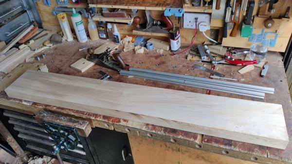
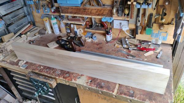
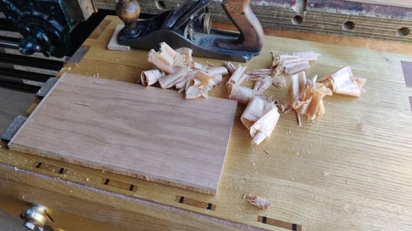
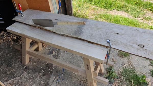
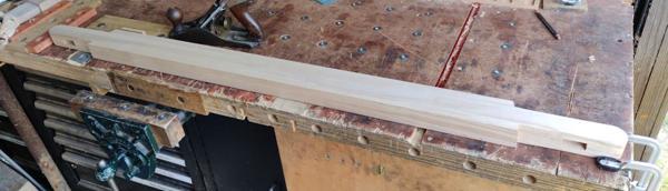
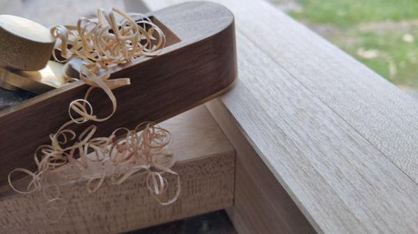
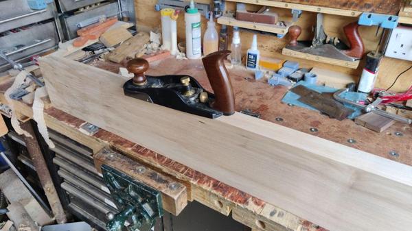
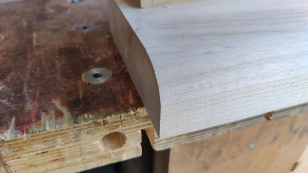
As I said in the last post, the next job was to smooth up the underside of the top planks (with a Stanley #4)...

2025-08-10-01-planing-underside_600.jpg


... and then get the inside edge perpendicular to the bottom face (with a high angle blade in a Veritas smoothing plane as the grain looked like it was going up and down a bit):

2025-08-10-02-planing-edge_600.jpg


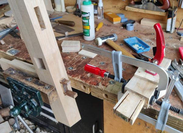
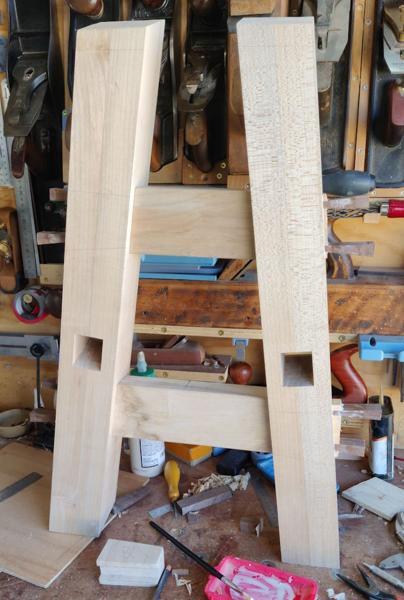
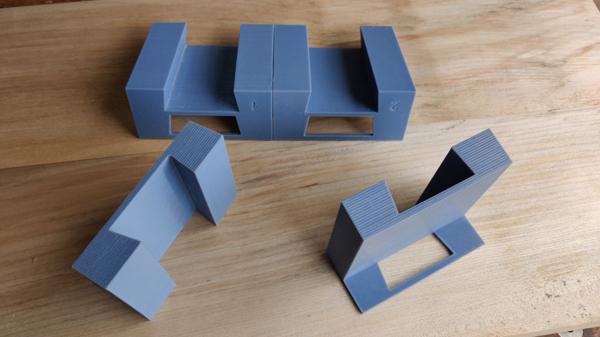
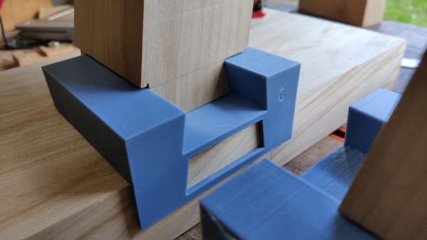
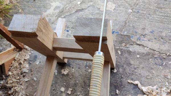
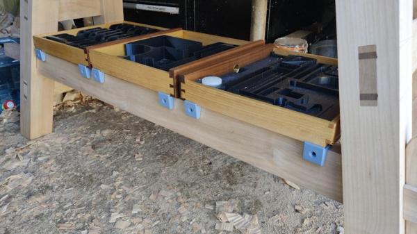
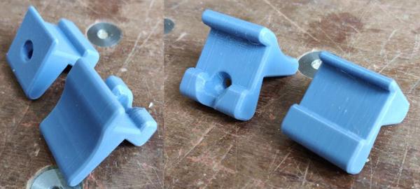
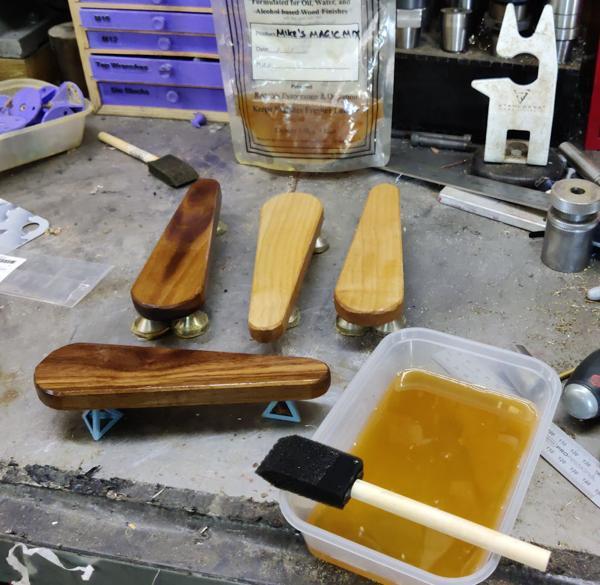
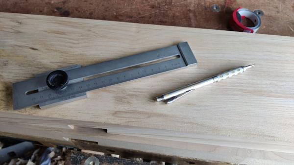
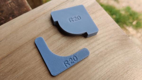
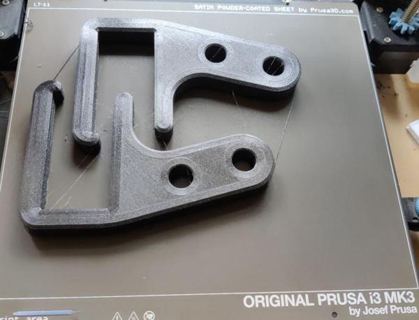
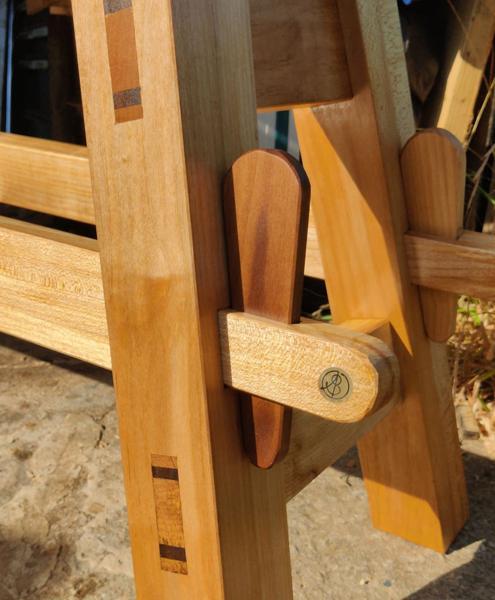
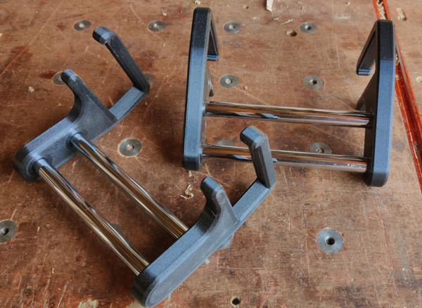
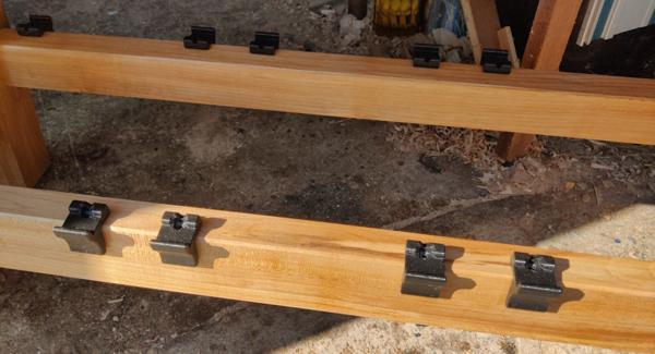
This brings us on to the next set of jigs/gauges from the 3D-printer:

2025-08-10-03-next-set-of-jigs_600.jpg


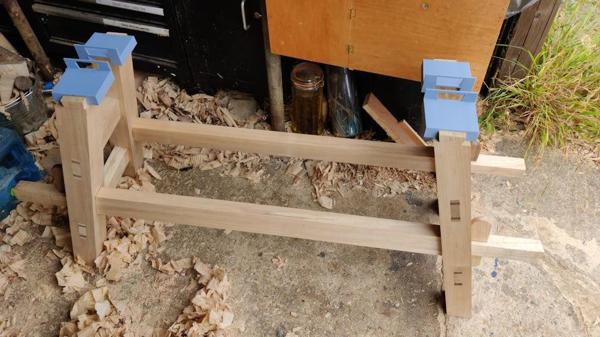
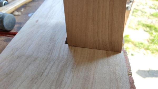
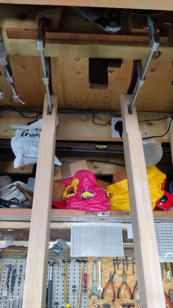
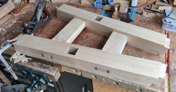
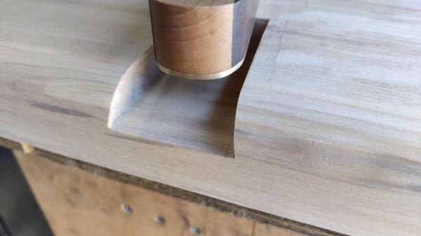
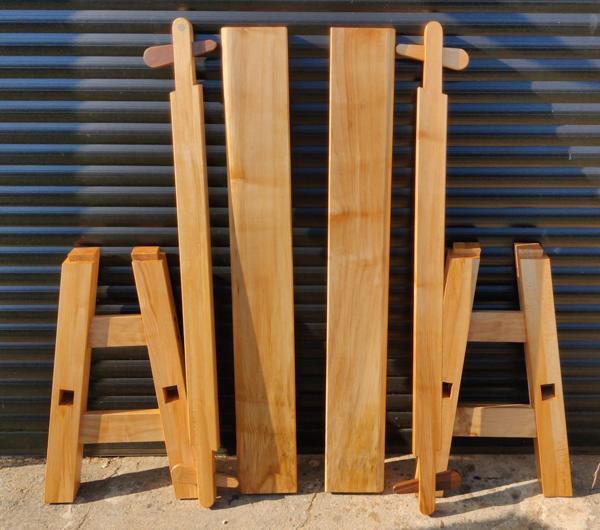
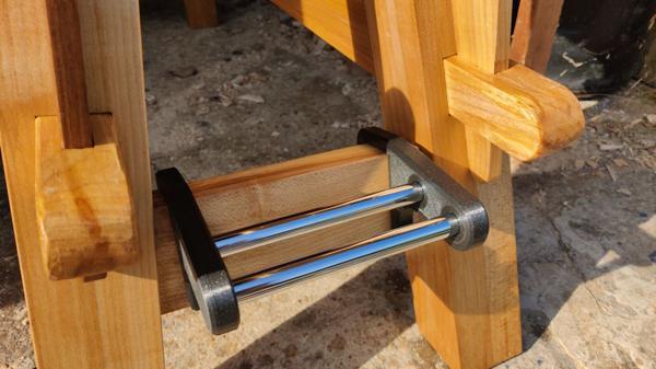
They got mounted onto the legs and tapped home until they're nice and snug on the taper:

2025-08-10-04-jigs-mounted-on-frame_600.jpg


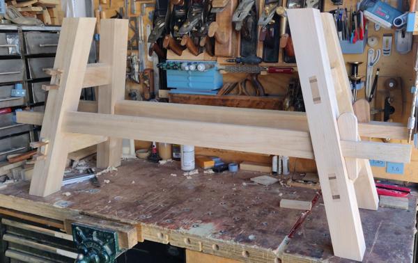
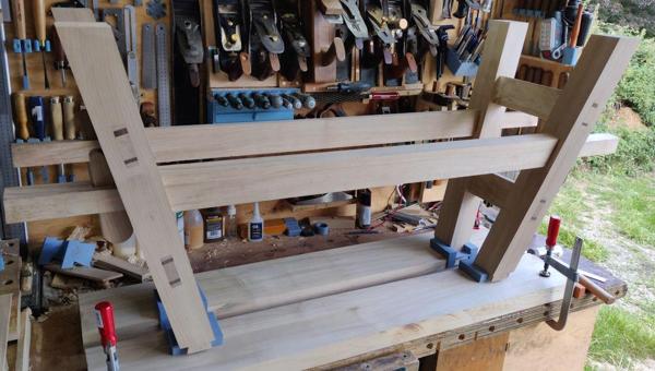
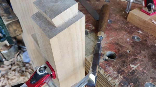
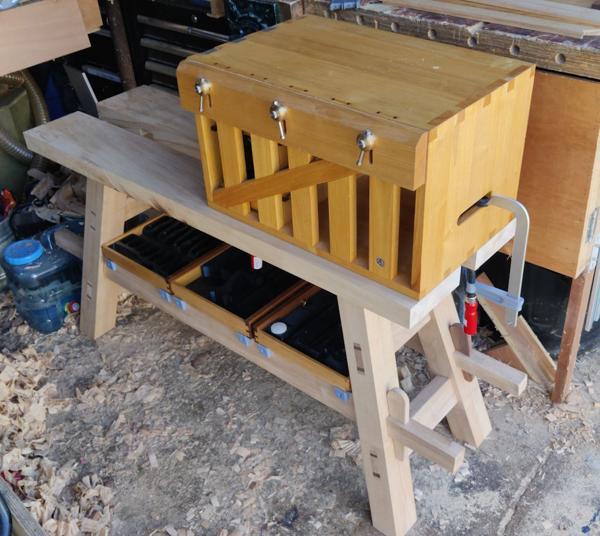
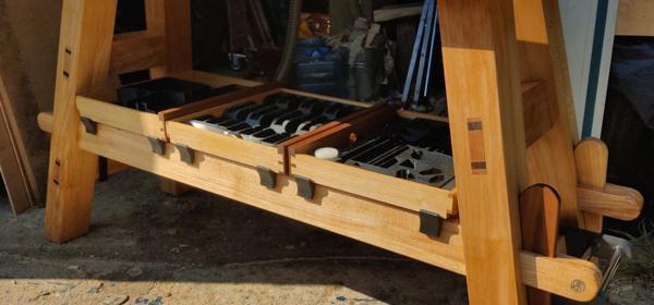
The top planks then got clamped to the bench and the whole frame got flipped over and plonked down on top:

2025-08-10-05-frame-inverted-on-top_600.jpg


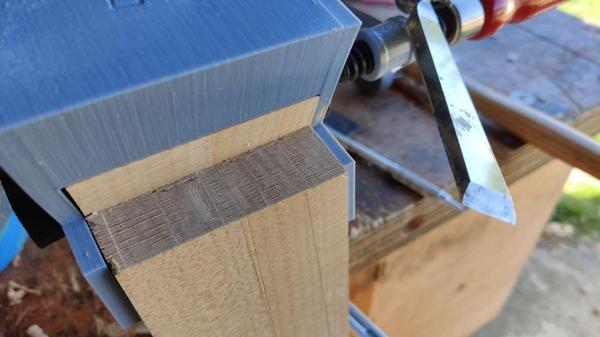
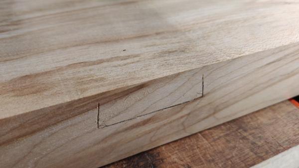
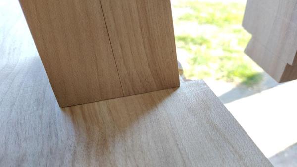
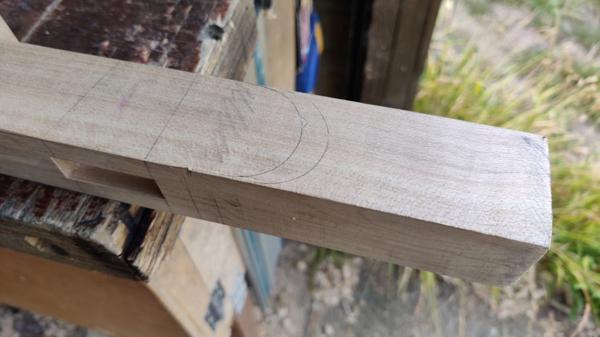
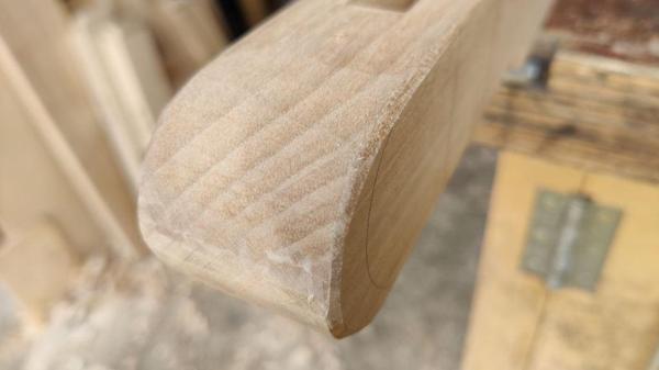
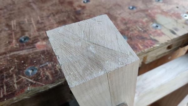
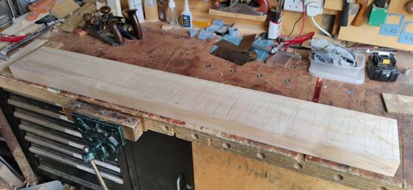
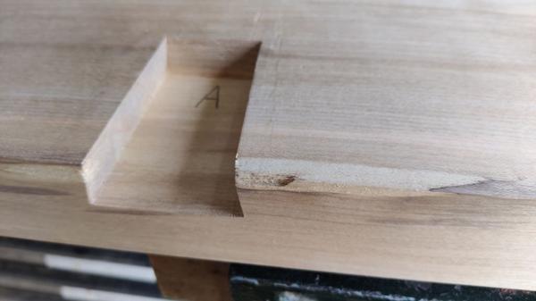
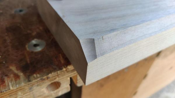
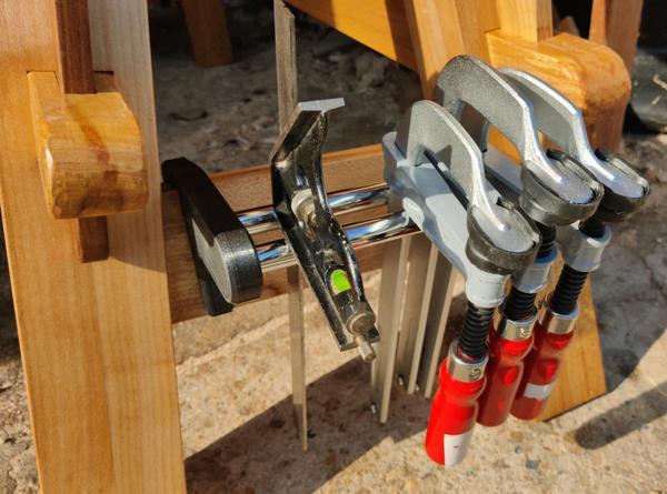
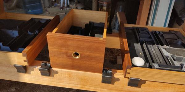
The little marking gauges show where the end of the dovetail needs to be marked onto the top pieces...

2025-08-10-06-marking-pocket_600.jpg


... leaving a mark that looks like this after following the gauge edges with a knife and then going over the knife lines with a pencil:

2025-08-10-07-marked-socket_600.jpg


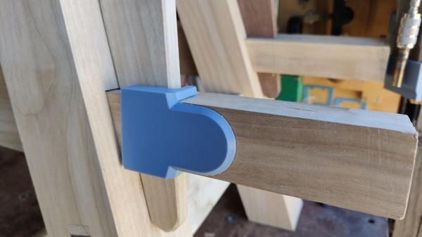
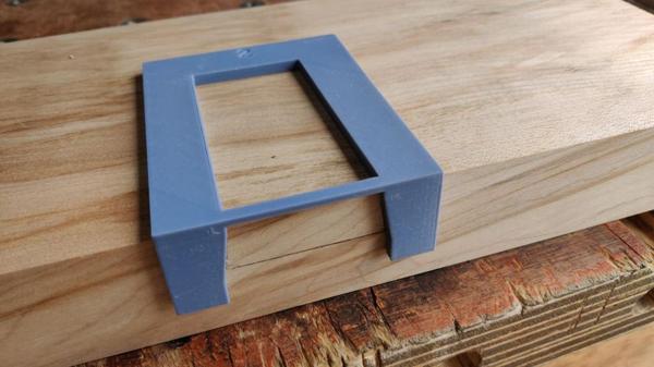
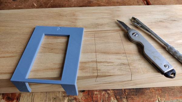
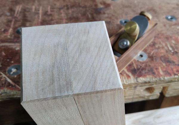
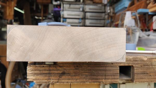
The lines don't go all the way to the top for the simple reason that I couldn't get the knife to the correct angle to be able to get into that part of the gauge due to the other top piece getting in the way. However, that's easily sorted, using the next little gauge, which also has the taper angle built into it...

2025-08-10-08-gauge-for-transferring-lines_600.jpg


... and leaves these marks on the top pieces:

2025-08-10-09-socket-marked-out_600.jpg


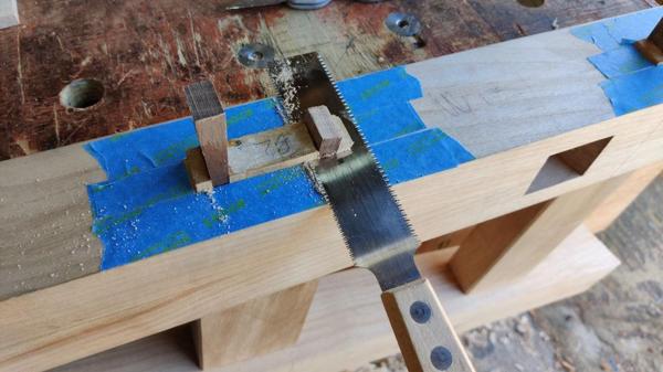
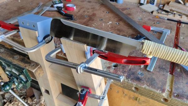
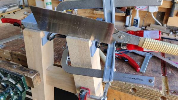
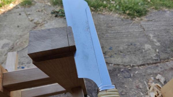
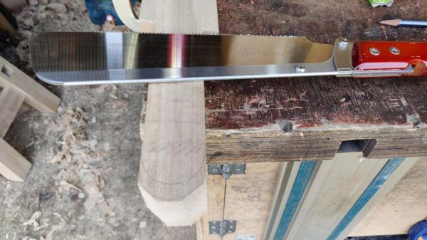
Before cutting the mortices, I needed to truncate the tenons so that the end of the socket is hidden nicely underneath (or should that be on top of?) the leg. I did that with a (rip-cut) Dozuki, starting by sawing straight down about 10 mm from the end...

2025-08-10-10-sawing-end-of-tenon_600.jpg


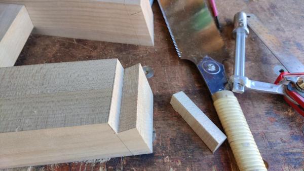
... and then coming across slightly above the shoulder line...

2025-08-10-11-cross-cutting-end-of-tenon_600.jpg


... before cleaning up the shoulder with a chisel:

2025-08-10-12-chiselling-cut-off-bit_600.jpg


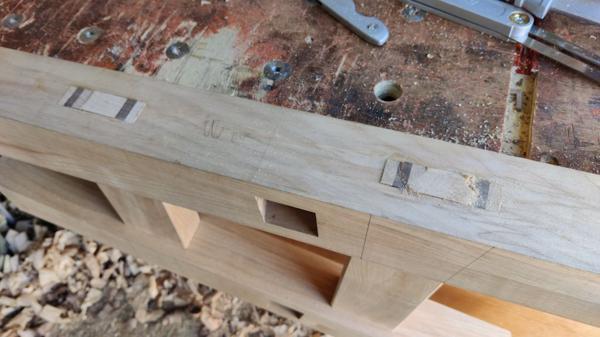
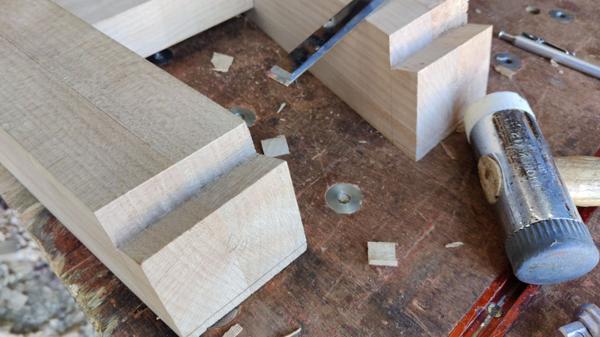
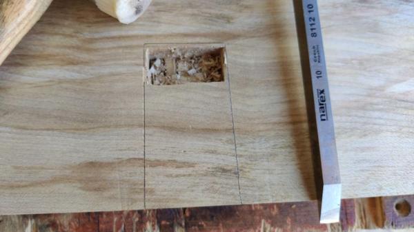
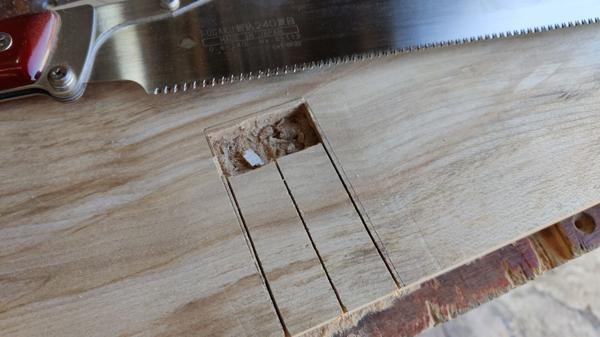
The tapered dovetail housing sockets were cut in a similar way to how I've done them in the past. I started with a 10 mm mortice chisel to open up a roughly 20 mm wide pocket at the far end:

2025-08-10-13-mortice-chisel_600.jpg


I then used a saw (initially a cross-cut Kataba but later a cross-cut Dozuki) to saw three cuts:

2025-08-10-14-cross-cut-dozuki_600.jpg


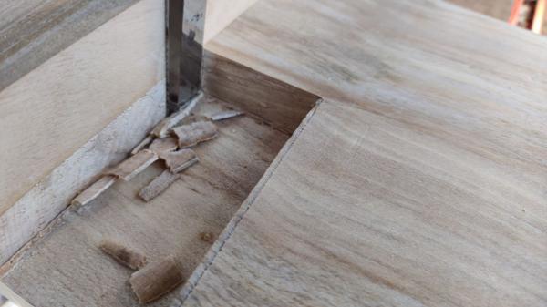
The router plane sorted out the bottom of the pocket:

2025-08-10-15-router-plane_600.jpg


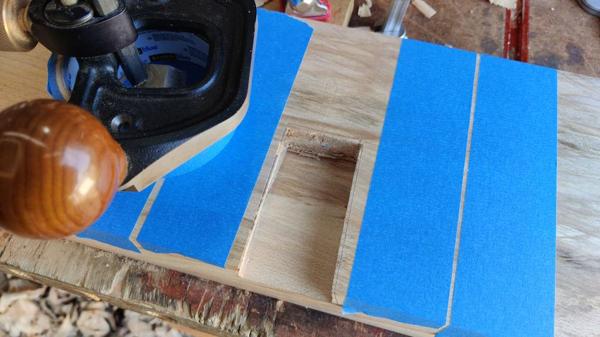
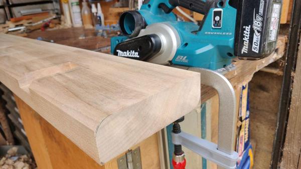
To get the socket edges at the right angle, I made a simple paring guide by planing a chamfer onto a handy bit of wood, with the angle checked by holding it up against the tails:

2025-08-10-16-planed-guide-with-taper-angle_600.jpg


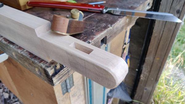
That got clamped to the top piece up against the knife line and the chisel could then follow its angled face to make the sides of the socket:

2025-08-10-17-paring-edges_600.jpg


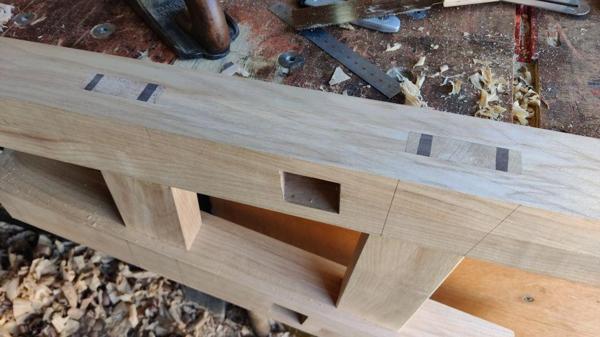
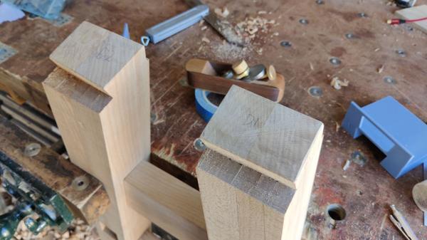
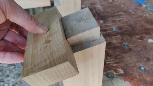
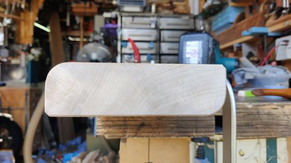
The first fit was, as I'd hoped, a little on the tight side but everything looked to be the right angle (i.e. it was tight at both ends rather than just one and it didn't rock):

2025-08-10-18-first-fit_600.jpg


When I've done tapered dovetail housings in the past, I've tweaked the tail/tenon to get the right fit, but this time (with a wide and relatively short socket and all the awkward angles on the leg frames) it seemed easier to tweak the socket. After a few goes back and forth taking off as little as possible each time I had a nice fit in about the right place:

2025-08-10-19-after-tweaking_600.jpg


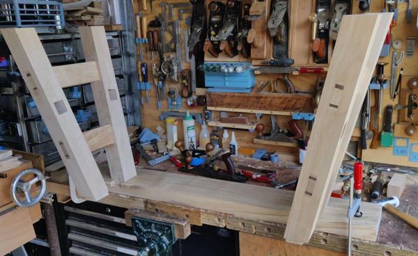
That process continued for the second socket on the first top piece until I had one plank fitted to both leg frames (but without the stretchers so this didn't prove the distance apart was correct):

2025-08-10-20-first-plank-with-two-legs_600.jpg


The other two sockets followed much the same process. One of them ended up at slightly the wrong taper angle (it was loose on the inside but tight at the outside) but that was spotted while it was still too narrow anyway so I managed to correct it before the socket was wide enough for the leg to go fully in.

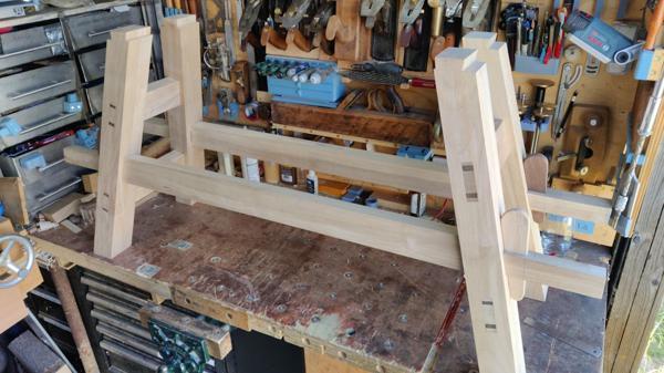
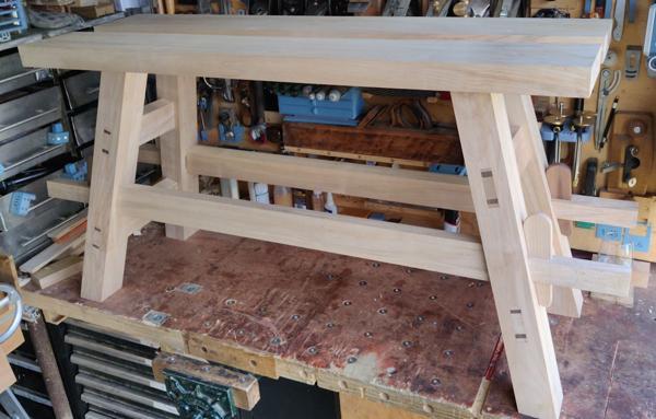
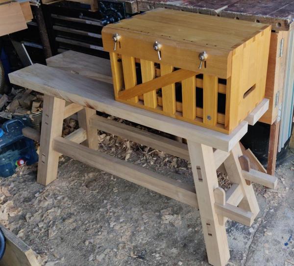
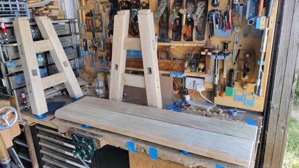
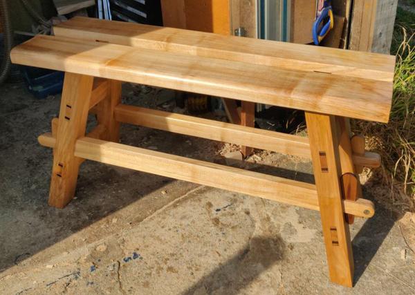
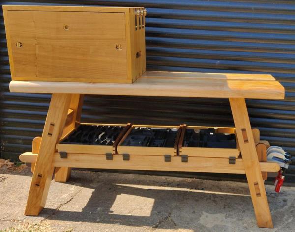
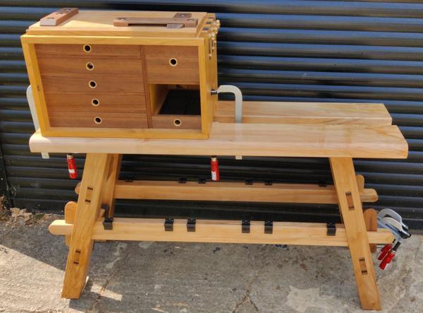
With all the sockets done, it was inevitably time to try assembling the whole bench and I'm very happy to say that it went together fairly easily and feels extremely solid. The gap between the top pieces is 60 mm. I was aiming for 50 mm, but bigger is fine: if I decide the overall bench width is too wide, I can trim the outside edges and inevitably as the dovetails wear, the planks will get a little closer together anyway.

It's fairly heavy (which I see as a good thing as it'll be stable) but I can still lift it: I assembled it on the floor and then lifted it up onto the bench for this photo:

2025-08-10-21-first-full-assembly_600.jpg


There's still a fair bit to do, but it's great to get to the point of having all the major joinery done. In this state, I could take it away with me on holiday and it would be usable, so anything I manage to do in the time I have remaining is a bonus but not essential.

The next job is probably to (very slightly) trim the ends of the top pieces (they're not square at the moment), then to plane the tops and outer sides of the top pieces. I'll also round over at least two of the long corners (to make it more comfortable if I sit on it to chisel on the top of the tool chest). After all that, the legs will need a once over with a smoothing plane and there's a few more jobs on the stretchers so it's far from finished but that's a major milestone crossed.
 
Phew!

I am pleased to see that you won't need to take the 3D printer on holiday too! ;)
 
It's getting much too hot to do anything useful in the workshop now, but I couldn't resist doing some quick experiments to see how it'll look and work. The first thing I did was place it next to my bench and put the travel tool chest on top. I'm happy to say that the top of the tool chest is at about the same height as the top of the bench, so I can count that as the first success!

2025-08-10-22-height-looks-right_600.jpg


I haven't ruled out shortening the legs of the bench (at the bottom, obviously), but if I do that I'll make some planks to go under the tool chest and lift it up to keep the same top surface height. One advantage of doing that would be that it would make sitting-down chisel work (where I'm sitting on the bench and chiselling on the top of the chest) more comfortable (probably). I'll do some experiments when I'm on holiday and see what feels right.

I can also confirm that there is definitely space for three drawers to sit on the stretchers:

2025-08-10-23-space-for-three-drawers_600.jpg


They're currently on some simple 3D-printed brackets, but the brackets are just resting there at the moment. I haven't decided whether to screw them to the stretchers or use double-sided tape (or something else) and I expect I'll probably tweak the design a bit (if I can think of ways to improve them). The final brackets will get printed in a different filament, probably the "Galaxy Black" PETG used for the drawer liners (but I'll have to buy some more of it first!).

With the tool chest sitting on top, it occurred to me that it would be good to test clamping it down using the hand-hold holes, which works fine:

2025-08-10-24-clamped-to-bench_600.jpg


That in turn allowed me to try planing on it to test how sturdy it felt. I grabbed a bit of bandsawn cherry and planed it smooth, first with a #5 (just because I knew it was already set for a fairly heavy cut) and then a #4:

2025-08-10-25-plane-shavings_600.jpg


The chest didn't budge at all, which is a great result. When I was taking heavy cuts with a plane and with the chest on the Makita mitre saw stand, it would occasionally lift up the end of the mitre saw stand under the force of planing. I dealt with that by leaning my foot against the saw stand's leg, but the mini-moravian bench is a lot heavier and I think that helps it stay put without any extra help.

The final thing I thought I'd try is one of the extra benefits I'm hoping to gain from this bench: somewhere to do long rips. I had a bit of Western Red Cedar in the garage and I clamped it to the bench and ripped off the edge with the big Ryoba:

2025-08-10-26-long-rip-cut_600.jpg


It worked like a charm so I'm really happy with that. The height felt about right for ripping. I started off with my knee on the cedar board (for comfort rather than stability: the clamps are doing the stability job) and it felt a good height for my knee. Towards the end of the board I just stood at the end without adding any extra weight to the cedar board and once again it felt nice and solid and stable.

We've got a heat wave coming over the next few days so I'll be doing my best to find excuses to be in an air-conditioned office as late as possible and then hiding from the sun when I get home; there won't be much in the way of updates on this project until the temperature cools down!
 
Glad it’s a success and a useful addition to the toolbox. Are you left handed btw?
The only thing I think I would change would be the overhang on the stretchers, but you did say you had more to do on them.
I have worked on my step ups occasionally and always for hand sawing using my knee to hold the wood down, I find 18”to be about the right height, what’s your measurement?
Edit Silly me just remembered you’re a lot taller!
 
Glad it’s a success and a useful addition to the toolbox. Are you left handed btw?

No, what makes you ask?

The only thing I think I would change would be the overhang on the stretchers, but you did say you had more to do on them.

Yep, cutting them down is one of the many outstanding jobs still to do on this project.

I have worked on my step ups occasionally and always for hand sawing using my knee to hold the wood down, I find 18”to be about the right height, what’s your measurement?
Edit Silly me just remembered you’re a lot taller!

Yes, much taller: 1.98 m / 6'6". Holding wood down with a knee works if you're using Western saws (where the saw is also pushing the wood down), but I don't think it's that practical for Japanese ones where the saw's trying to lift it up. I find clamping it a lot more comfortable. For short cross-cuts I'll just hold it against a stop of some sort (think of it as a reverse bench-hook), but for long rip cuts the amount of time spent sawing means that the time putting clamps on is negligible by comparison.
 
It was the way the saw was left in the wood with the big bit on the right, I always have the big bit under my knee on the left. But then I use a traditional saw.
Ah, that makes sense. With it clamped down, it doesn't matter that much. Sawing with a Ryoba, I stand (or kneel) so my body is in line with the saw (rather than sawing to the side of the body like you would with a Western saw), so it felt quite natural to stick my right knee on the far side of the board, my left foot on the ground on the near side and hence have my body roughly in line with the cut line.
 
This evening was the first time in a few days where the temperature has been (barely) low enough to do anything. It's far too hot to contemplate planing the top and outside edge of the top pieces, but I thought I'd have a go at shortening the stretchers.

I decided to err on the side of caution and move the round-over lines a bit further out. It'll be easy enough to shorten them later and it'll be a lot more difficult to extend them!

2025-08-13-01-moved-roundover-mark-out_600.jpg


The shape was rough-sawn out with the cross-cut Dozuki:

2025-08-13-02-rough-sawn-to-shape_600.jpg


I then grabbed my little home-made block plane (which is becoming one of my most often used planes) to round the end off:

2025-08-13-03-smoothed-with-block-plane_600.jpg


Close up of a finished stretcher end:

2025-08-13-04-block-planed-surface_600.jpg


All four stretcher ends have been rounded off now so that's another small job ticked off the list.
 
We've got a heat wave coming over the next few days..... and then hiding from the sun when I get home; there won't be much in the way of updates on this project until the temperature cools down!
Too bloomin' true! Even up in Geordie Land (equating to "sub-arctic" for some) the daytime temperature here is in the thirties* for the fourth time in a month. I have two 'suntraps' here and they are unbearable from about 11.00am to 5pm.

*No, not the Stevenson Screen version, the concrete panel garage version!
 
That's look great Al.

I've basically given up using flush cut saws. I cut a through tenon with one. It was flush on the entry and exit of the cut, but was at least 0.5mm below the surface in the middle. They're too flexible and just go wherever the want too!
Agreed, they do tend to go walkabout. In an old plastic kitchen storage tub I've got oddments of 0.6mm veneer stuck to bits of parcel tape which for all practical purposes (according to Rob Ingham) has zero thickness, so the 'flush' cut saw leaves a scant half mm or so to then clean up - Rob
 
I've made another version of the drawer supports, with a slightly more curvy shape and also with the screw hole in the other face. I've only printed one so far (and the final ones will be in a different colour as I've said before), but I'm feeling a bit happier with them so far:

2025-08-14-01-improved-drawer-support-shape_600.jpg


It was still feeling too hot to work on the top pieces, but I thought I could probably cope with a light smoothing plane pass on the stretchers:

2025-08-14-02-planing-stretchers_600.jpg


I also gave the corners a chamfer, using this little chamfering plane:

2025-08-14-03-chamfering_600.jpg


I followed that up with a single stroke from a block plane with a high angle blade just to improve the edge a little. I don't normally bother with that little chamfering plane, but I wanted a consistent chamfer so that I can match that chamfer in the 3D-model of the drawer supports to get them to fit really nicely.

With that, the stretchers are essentially complete (give or take fitting drawer supports and such like), so I took them down to the other end of the garage and hung them up on some clamps ready for oiling:

2025-08-14-04-hung-up-for-oiling_600.jpg


I've given them the first coat of Mike's Magic Mix but haven't taken any photos of them oiled, so you'll have to wait to see them. As a spoiler, I also gave the wedges a quick smooth and then oiled them as well; here's a photo after applying the oil but before wiping the excess off:

2025-08-14-05-oiled-wedges_600.jpg
 
Missed a few recent posts, just caught up. The bench looks brilliant. I liked the way you used the 3D printed jigs to ensure you got the angles right after investing so much time in the pieces you were cutting. It's in interesting mix, which I really like,using the latest technology to enable you do to the work by hand.
 
I've just been reading your recent posts on this project ( - I'm still trying to understand all those compound angles ... ). But the finished bench is very impressive!
Les
 
I've just been reading your recent posts on this project ( - I'm still trying to understand all those compound angles ... ). But the finished bench is very impressive!
Les
Thank you Les. The compound angles hurt my head too!

"Finished" is stretching it a bit though: the top pieces need a lot more work (one edge is still rough sawn & the top surface is quite rough too). The leg frames still have a bit of fettling to go too.
 
I started relatively early this morning while it was still cool-ish outside. The first job was to clean up the leg frames ready for oiling. I started by supporting them in the vice so that I could deal with the rough-sawn bottom of the feet:

2025-08-16-01-rough-sawn-foot_600.jpg


After planing and chamfering with my little home-made block plane:

2025-08-16-02-planed-and-chamfered-foot_600.jpg


No doubt they'll get beaten up a bit in use, but it's nice to start with something smooth.

With that done, I could plane the remaining two faces of the leg frames...

2025-08-16-03-planing-remaining-leg-faces_600.jpg


... and apply a light chamfer on the remaining edges:

2025-08-16-04-chamfering-leg-edges_600.jpg


With that, the leg frames are, I think, ready for oiling.

I had planned the first job on the top pieces to be planing the edges, but after a bit of a ponder I decided to make them slightly narrower first. That was done by marking up with a pencil and the edge distance gauge thing...

2025-08-16-05-top-pieces-marked-for-trimming_600.jpg


... and then covering the bench in sawdust with the tracksaw:

2025-08-16-06-making-a-mess-with-the-tracksaw_600.jpg


After that, the sawn edges could be planed smooth:

2025-08-16-07-edge-planing_600.jpg


Ideally, I'd probably plane the top surfaces while the bench was assembled. That way, I'd be able to make sure that the two surfaces were co-planar. With the stretchers in the slow process of being oiled, I can't do that at the moment, so I decided to just plane them smooth for now. If there's enough of a discrepancy to worry about, I can always plane them again later (even if that's after they've been oiled).

For now, I gave the surface a quick once over with a pencil so that I could see when everything had been planed...

2025-08-16-08-face-planing-before_600.jpg


... and then went over the surface with a #4 until the pencil marks were all gone.

2025-08-16-09-face-planing-after_600.jpg


Next up, I marked up the four corners on the end to show what I want to do to them:

2025-08-16-10-marked-up-end_600.jpg


That's two corners with a 20 mm fillet (round-over) and two corners with a small-ish chamfer. The outside upper corner is getting rounded over to make it more comfortable to sit on with one leg either side. The chamfered corners are being chamfered just because it seems like a good idea to avoid sharp edges.

The inside bottom corner is being rounded over for a slightly weirder reason. On one of the top pieces, there's a bit of sap-wood near one of the dovetail sockets:

2025-08-16-12-reason-for-internal-roundover_600.jpg


Given that it's on the inside and underside, that brittle sap-wood probably isn't a problem, but I figured that a round-over wouldn't hurt (when the joint is assembled, the leg is much further in than the round-over will reach) and that it was a relatively elegant way of getting rid of that sap-wood.

It probably won't surprise anyone who's been reading this that I made a couple of 3D-printed gauges to help get a consistent fillet radius:

2025-08-16-13-gauges_600.jpg


One of them was used to mark the ends (as seen in the photo above). You'll see the other one in use shortly.

It was already starting to get rather hot in the workshop so I decided to make my life a little easier by roughing the big fillet out with a couple of passes with a planer:

2025-08-16-14-two-passes-with-planer_600.jpg


That left me with a heavy chamfer that was then not too much work to plane to shape using my block plane. The second little 3D-printed gauge was used to give me an idea of whether I was close to the target radius:

2025-08-16-15-planing-to-shape_600.jpg


I wasn't aiming for perfection here: it won't be perfectly round, it won't be the perfect radius and it won't be absolutely consistent all the way along. However, the gauge gives me an idea of when it's near enough.

For the smaller chamfers, I just did those with a handful of passes with the block plane (i.e. without bothering with the electric planer).

One of the top pieces has been done (and also had the end-grain corners block-plane chamfered):

2025-08-16-16-finished-shape_600.jpg


If I haven't overheated by the time I've had lunch, I might have a go at the other one this afternoon. If it feels too hot then it'll be a job for first thing tomorrow morning.
 
I did manage to get the other top piece done yesterday (but was it was too hot in the room with the computer to want to post any pictures). Remember that sappy bit of wood near the dovetail socket?

2025-08-16-12-reason-for-internal-roundover_600.jpg


This is what it looks like now:

2025-08-16-18-sap-gone_600.jpg


On the final corner (the top outside corner of the second piece) I experienced one of the reasons I dislike power tools: when you make a mistake and slip slightly it has a big effect. The planer's nose dived a little (I obviously wasn't pushing down enough at the back) at the end of the pass:

2025-08-16-19-planer-oops_600.jpg


The radius on that edge is now slightly bigger than the radius on the other four, but you'd have to be looking extremely carefully to be able to tell:

2025-08-16-20-planer-oops-gone_600.jpg


With that done, I decided all the remaining pieces were ready for their first coat of Mike's Magic Mix, so I arranged them on the workbench:

2025-08-16-21-ready-for-oiling_600.jpg


The stretchers and wedges have now had three coats; the leg frames and top pieces have had one (I haven't taken any post-oil photos yet). I'm aiming for four coats on everything I think, so the last coat will probably be on Tuesday evening.

As I said in the last post, I think there's a reasonably high chance I'll end up planing the top surface of the top pieces again (once the frame is assembled). If so, then the top surfaces will have to have another four coats, but (being a relatively small area and only one face) that shouldn't be too much hassle.
 
Since the last post, I've been applying lots of oil and the last coat was applied last Tuesday. I've been away since then but came back last night so this morning it was time for the final photo shoot. I say final, but I'll almost certainly get some more (and probably better) photos once I've taken the chest and the bench away to France in a couple of weeks.

Before we get onto the photo shoot, there were a couple of other minor jobs that I wanted to get done. The first of these was lots of 3D-printing, firstly to re-print the drawer brackets in "galaxy black" filament and also to print some of these:

2025-08-25-01-printer-busy-again_600.jpg


Can you guess what they are yet? They were quite slow to print as I went for about 10 perimeters and 60% fill density to make them as strong as reasonably possible.

The other job I wanted to do was drill a 4 mm deep, 20 mm diameter hole in the end of one of the stretchers (note that this does mean I won't be able to decide to shorten the stretchers at a later date, but I think I'm happy with that):

2025-08-25-02-one-last-hole_600.jpg


That hole was used for one of my logos:

2025-08-25-03-with-logo_600.jpg


With that glued in place and all the printing done, I could assemble all the oiled wooden bits for a dismantled photo...

2025-08-25-04-all-the-wooden-bits_600.jpg


... and then put them together for this one:

2025-08-25-05-assembled_600.jpg


A detail shot showing some of the joinery:

2025-08-25-06-joinery-detail_600.jpg


Those 3D-printed bits got assembled together with some chrome-plated copper pipe from Screwfix:

2025-08-25-07-clamp-racks-assembled_600.jpg


They get clipped onto the lower cross-bars at each end...

2025-08-25-08-clamp-rack-fitted_600.jpg


... and provide somewhere handy to store F-clamps and perhaps the combination square:

2025-08-25-09-clamp-rack-filled_600.jpg


I've also fitted now fitted the drawer supports:

2025-08-25-10-drawer-supports-taped-in-place_600.jpg


The eagle-eyed among you will notice the lack of screws in the screw holes. For now I've just fixed them in place with double-sided tape. If I find I'm using them a lot when I'm away, I'll fit the screws. If I don't use them then I can peel the tape off a lot more easily than fill in screw holes!

The drawers fit nicely and feel stable:

2025-08-25-11-with-drawers_600.jpg


The central two supports on each stretcher are positioned so that, if I choose to, I can mount the narrower router plane drawer there, although it's not as well supported:

2025-08-25-12-with-smaller-drawer_600.jpg


If I find I want to do that a lot, I can 3D-print some extra bits that slot into the existing ones and support it properly.

To finish off, here's a couple of photos with the chest on top; firstly just resting and all closed up...

2025-08-25-13-with-chest-oon-top_600.jpg


... and then clamped in place properly, with the photo showing off how uneven the ground is outside my garage!

2025-08-25-14-with-chest-clamped-wonky-ground_600.jpg


I've got some spacers prepared to go under a leg in case I need to stabilise it when I'm away, but I'm sure it won't be as bad as this patch of ground.

And that, as they say, is that. Thanks for reading.
 
Magnificent. You've developed a highly personal style, featuring plenty of original thinking, complex joints accurately made and CNC design and 3D printing blended into hand tool woodworking.

I am sure you will have many hours of pleasure using it. Thanks for taking us along for the ride.
 
Back
Top