• Hi all and welcome to TheWoodHaven2 brought into the 21st Century, kicking and screaming! We all have Alasdair to thank for the vast bulk of the heavy lifting to get us here, no more so than me because he's taken away a huge burden of responsibility from my shoulders and brought us to this new shiny home, with all your previous content (hopefully) still intact! Please peruse and feed back. There is still plenty to do, like changing the colour scheme, adding the banner graphic, tweaking the odd setting here and there so I have added a new thread in the 'Technical Issues, Bugs and Feature Requests' forum for you to add any issues you find, any missing settings or just anything you'd like to see added/removed from the feature set that Xenforo offers. We will get to everything over the coming weeks so please be patient, but add anything at all to the thread I mention above and we promise to get to them over the next few days/weeks/months. In the meantime, please enjoy!

Restoring an electric drilling machine

AndyT

Old Oak
Joined
Nov 23, 2020
Messages
3,880
Reaction score
1,803
Location
Bristol
Name
Andy
I was able to chat with @toolsntat in person this week, and was very pleased when he showed me something he'd picked up recently. Inspired by this shot
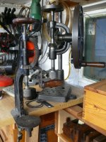
P1100042.JPG

of the corner of my workshop where several bench drills / drill stands squeeze in together beside the miniature bandsaw, he thought that what would go well there would be another drilling machine!

But not just an ordinary machine. Apparently he'd been buying some tools from the workshop of someone who had been a skilled model engineer and had picked this little thing up from where it had been abandoned, unloved in the dirt and detritus of the years.

P1100059.JPG

What could I do to resist? Nothing! He's just so persuasive. Admittedly, there is some dirt on it

P1100062.JPG

and some of the wiring was a bit crispy, and also too short to connect to a new plug! ;)

P1100066.JPG


but it looked like it could be revived, so I accepted it gratefully and brought it home.

Looking at it together, we noticed a few things, apart from the dirt.

It's probably been built by the previous owner, maybe with commercially available castings, or modified from another machine.
The vertical travel is short - it's only about 10mm - but there is a very fine, calibrated depth adjustment.
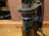
P1100061.JPG

On top, there's a tap wrench. Did this serve as an especially hazardous sort of finger-bashing flywheel? Did I need to make something safer? (I reckon I could.)
If I can't get it to work, at least I'll have an extra tap wrench.

P1100060.JPG

Today I spent a few happy hours hiding from the sun and cleaning it all up a bit.

I was pleased to find that the dirt was all just superficial and came away easily.

P1100081.JPG

The odd bits that were rusty were easy to clean up with a brass wire brush and a Garryflex block.
The main spindle rotates freely with no discernible play.

The main structure seems very neatly made, but the shaft changes from 35mm diameter and smooth down to about 34.5mm and rough and rusty. I can't see why; maybe it's because the shaft was salvaged from something else or maybe there was a design change or even a mistake. The collar on the table still grips ok on the smaller section.

There's a protective plastic shield around the motor which is a bit flimsy and split here and there. The brackets that hold it look a bit casual compared to the rest and at present there's nothing to hold the mains lead from being pulled out of a chocolate block connector. For the time being, all I did was to reassemble it as it was, to see if it works. If it does, then I could try to make a better cover with safer wiring. To mend the splits I applied some gaffer tape.

P1100094.JPG

The motor has a comprehensive data plate, showing where to place the little jumpers for various supply voltages:


P1100091.JPG
and they are installed to suit 220 v AC

P1100082.JPG

That photo also shows a thin blue wire. I don't think it was connected to anything. It could have been caught up on the body of the switch or held between the wiring block, touching but not twisted onto the earth connection. (For now, I have insulated the end and not connected it at all.)

Having brushed off most of the dirt, I checked with a multimeter. I found a resistance of about 120 ohms across live and neutral, no shorts to earth, and that the double pole switch seemed to be ok.

I connected a new lead, plugged it in and turned it on. The motor ran sweetly with no nasty noises, no bad vibrations and no release of magic smoke.

After that I just cleaned a bit more dirt off and reassembled the motor guard and wiring.

It looks like I have a working piece of precision drilling equipment!

P1100097.JPG

But I do have some more questions...

At present, there's nothing to connect the motor shaft to the pulley on the drill shaft, so I think I need to buy a loop of suitable heavy duty rubber band. That looks fairly easy; there are plenty of vendors on eBay with a wide range of sizes for little outlay. But do I need a pulley on the motor shaft?

I do have this one, in a box of useful bits, and I could make a bushing to reduce the size of the hole. The rubber band is just to show that the drive belt would clear the castings ok.

P1100093.JPG

But there's no sign of a pulley having been on that shaft - no marring from a set screw. Maybe it should be used without one, like this?


P1100092.JPG

Looking back at the motor plate, presumably "6300 U/min" means 6300 rpm? According to my copy of "The Amateur's Workshop" by Ian Bradley, HSS drill bits making holes in mild steel don't need to go above 2000 rpm for an 1/8" diameter. The motor shaft is 7.5mm diameter and the pulley is 30mm, so I'd be getting a 4:1 reduction, ie 1575 rpm, which sounds plenty to me. Does that look a likely arrangement? My randomly selected rubber band didn't rise up off the shaft, but it looks a bit odd having nothing on the top of the shaft to prevent that. What would be the right diameter of round belt to use, and would it be ok on a 7.5mm shaft?

All comments and suggestions will be gratefully received!

And thanks again to Andy B for his generosity.
 
Last edited:
I think I have some polycord belting if you want a bit sending.
 
I can't help you at all, Andy......not with your questions, nor any general insights into this tool, nor with your tool addiction in general. :) What I'm really curious about, though, is who needs a drill with only 10mm of travel, and a very finely-set control over the depth of drilling? A watchmaker? A jeweller? A model engineer?
 
I think this is what model engineers had advertised in M.E. and M.E.W.* as "sensitive drills". Never had one, but the ads showed similar, restricted travel models (by wood-working standards) and a diverse range of ways to do so. George H. Thomas's design, for home building, comes to mind as a possible inspiration for this one.
As to:
who needs a drill with only 10mm of travel, and a very finely-set control over the depth of drilling? A watchmaker? A jeweller? A model engineer
All of the above!! Setting blind holes and tapping them (for the last on the list) comes to mind. Cowell's made a tiny lathe and exquisite dinky drilling machine for just such purposes,that I am sure you can find reference to Andy. They were, and still are "Holy Grail" machines(?) for metal stranglers. I know one member here has said lathe, and, if aproached nicely, we could get some photos for you if needs be?
This partial homebrew wee beastie is emblematic of the fifties, early sixties, when model engineering was in its heyday.
Nice gesture. Fascinating bit of kit...if only it could talk.
Sam

*Model.Engineer. 1920's to today. Model Engineers' Workshop. 1980's to today. Indices for both are available.
 
Thanks all for the helpful responses - the hidden world of 1950s model engineering is being gradually revealed to me!

I can't help you at all, Andy......not with your questions, nor any general insights into this tool, nor with your tool addiction in general. :) What I'm really curious about, though, is who needs a drill with only 10mm of travel, and a very finely-set control over the depth of drilling? A watchmaker? A jeweller? A model engineer?

Good questions, to which I did not know the answers, except that I liked your guesses and then Sam came along to confirm the answers.

I think this is what model engineers had advertised in M.E. and M.E.W.* as "sensitive drills". Never had one, but the ads showed similar, restricted travel models (by wood-working standards) and a diverse range of ways to do so. George H. Thomas's design, for home building, comes to mind as a possible inspiration for this one.
As to:

All of the above!! Setting blind holes and tapping them (for the last on the list) comes to mind. Cowell's made a tiny lathe and exquisite dinky drilling machine for just such purposes,that I am sure you can find reference to Andy. They were, and still are "Holy Grail" machines(?) for metal stranglers. I know one member here has said lathe, and, if aproached nicely, we could get some photos for you if needs be?
This partial homebrew wee beastie is emblematic of the fifties, early sixties, when model engineering was in its heyday.
Nice gesture. Fascinating bit of kit...if only it could talk.
Sam

*Model.Engineer. 1920's to today. Model Engineers' Workshop. 1980's to today. Indices for both are available.
That background info helped a lot. I soon learned that kits of ready made castings are still available eg from Hemingway (as mentioned elsewhere on this forum by @Dr.Al) who still sell a kit based on George H Thomas's designs, or from Kennions.

Looking into Sam's suggestions, I searched in archived issues of Model Engineer for sensitive drills and found articles like this one from 1955 which assumes that the reader will not only be able to make their own patterns but will also cast the iron required. Sample pages:

Model Engineer Vol 112 No 2808_0008.jpg

Model Engineer Vol 112 No 2808_0009.jpg

Looking closely at my drill, most of the iron parts look professional, but the central yoke that lifts up and down looks as if it has been sawn out of flat stock. Notice the odd series of part-cut holes and the simple nut and bolt fixing.

P1100076.JPG

Maybe the maker had bought (or repurposed) some parts and made others, then painted everything to match. The yoke that holds the motor would have had to be customised to suit the motor used.

I think I have some polycord belting if you want a bit sending.

That's a generous offer and very helpful. Looking at the pictures from the 1950s magazine, the builder seems to have used some sort of similar round belting. It's hard to know what length I will need and whether I need to put a pulley on the motor shaft, so an odd length that I can experiment with would make sense. (I found an encouraging YT video showing how easy it is to weld the ends together.) I'll send you a pm with my address.

Thinking about jobs where I might enjoy using this drill, I realised that, possibly, the reason why there was a tap wrench on the main shaft could be that the last user was in the habit of clamping the workpiece onto the table, drilling a suitably sized hole, then swapping the drill bit for a tap and turning it by hand, letting the shaft keep it perfectly upright and the gentle spring pressure letting the thread draw the tap down.

I have also noticed that the Jacobs chuck is an excellent one, closing down tight enough to take a 0.5 mm drill bit, should I ever need it to.
 
Last edited:
After languishing on my workshop floor and being tripped over for over 12 months now I'm so glad to see the progress you have made Andy in attempting to bring this back to life.
Thanks for taking it on.
Cheers, Andy
 
then swapping the drill bit for a tap and turning it by hand, letting the shaft keep it perfectly upright and the gentle spring pressure letting the thread draw the tap down

Perzactly Andy. Indeed, if you scrounge around in M.E.W. a bit further, you will.find at least two designs (verging on Heath Robinson it must be said) for building permanent "tapping stands" on this basis. One utilised an old B&D drill stand, with the addition of a sleeve for the shaft bearing a chuck to hold the tap. Can't remember the other, but I did raise an eyebrow over both in terms of accuracy. Needs must, I s'pose. Micawber was right after all, and if it got the job done, who's me to cast nasturtiums?
Sam.
 
Perzactly Andy. Indeed, if you scrounge around in M.E.W. a bit further, you will.find at least two designs (verging on Heath Robinson it must be said) for building permanent "tapping stands" on this basis.

I made Harold Hall's design for a tapping stand a few years ago. It was a fun project but truth be told it doesn't get used much. It's quite handy for small threads in things you really really don't want to mess up though.

1755445772017.png
 
I made Harold Hall's design for a tapping stand a few years ago. It was a fun project but truth be told it doesn't get used much. It's quite handy for small threads in things you really really don't want to mess up though.

View attachment 35150
Ah yes, I should have remembered him. It's an ingenious design, using an existing thread of the same pitch to advance the tap at the right rate - more info here - http://www.homews.co.uk/page41.html. He's another clever model engineer who built himself a drilling machine using unfinished castings - http://www.homews.co.uk/page434.html and who has another YT channel I need to look at. Thanks Al.
 
Nice one Al, I'd forgotten about Harold's website.

He was a true engineer, totally steeped in his speciality; I had a telephone natter to him once, lovely fellah, huge knowledge of engineering competencies.
 
Perzactly Andy. Indeed, if you scrounge around in M.E.W. a bit further, you will.find at least two designs (verging on Heath Robinson it must be said) for building permanent "tapping stands" on this basis. One utilised an old B&D drill stand, with the addition of a sleeve for the shaft bearing a chuck to hold the tap.

Was it this one?

tpt01.jpg


It seems to be a popular (and sensible) idea.

 
Was it this one?

tpt01.jpg


It seems to be a popular (and sensible) idea.

Sure looks like it! I also have a vague memory of one that made the 'axis' longer by fastening a steel plate on each side and then a second bearing at the top, to increase rigidity.
I'm with family presently, in the hectic (grockles everywhere) southern Lakes and my collection of use -ful/less impedimentia is 140 miles away. I'll sharpen up (if I can, at nearly 70) later in the week when I get back to Tigh na Q.
Sam
 
What... you mean to tell me that just holding the tool on the grinding wheel and jiggling it about randomly isn't good enough? I might have to give up on all this metal malarkey! :)
 
Apoligies for going off piste, on the subject of home made stuff I picked this lovely thing up from a house clearance recently. After watching stefan gotteswinter youtube video I realise the guy made himself a D bit grinder.

c7992a3b-1a7d-439d-b801-fd99f6cb49c2.jpg
 
Not sure of the composition of the drive belt referred to but if it’s made up of multiple strands like the tiny belts I use on Automata the method I use to cut and rejoin them is simply to wrap electricians tape around where the cut is to be made to hold it all together, cut both ends very carefully at 90° and the stick back together with superglue, then remove the tape. The superglue does travel down the strands though resulting in a bit of belt that’s stiff so minimal glue is the way to go.
Ian
 
I really like my Bradson hand-cranked pillar drill. You have to adjust it up and down the shaft quite a bit as it has limited travel, but it's no big deal. Like Andy's it can be wall-mounted for more height I think, but I've never tried it. When I was making my travel tool chest, I took advantage of the limited travel to set the height of the column such that it would bottom out at the right place (and hence remove any risk of drilling too deeply).


1755527813548.png

The only (quite big if I'm honest) downside with it is there's quite a lot of run-out on my one (i.e. if you grab the chuck and try to move it back and forth and left-to-right, it moves more than I'd like). I'm planning to do something about that at some point, but I expect it'll be years away rather than weeks away. However, if you're looking to buy one (and especially if you're choosing between several), it's worth looking to see how much play there is in the shaft. Too much run-out risks making non-circular holes.
 
I really like mine and do use it from time to time.

There were quite a lot of designs made, with different features that you might find important.

- Automatic feed. This can be (like mine) by having a small clutch on the shaft which will steadily lower the drill bit, unless there's too much resistance from the work. Other models had a visible ratchet, giving a choice of slow or faster feed.

- Choice of speeds. Generally by having two bevel gears, large or small, as on many portable breast drills. The lower speed gives you more torque, which can be useful for bigger holes.

- Size. Some are lightweight tiddlers, others are capable of heavier work. Catalogues show the same designs in a range of sizes.

- Chuck. Ideally, a good three jaw chuck with a key. Mine is just tightened by hand and needs a good grip.
Beware of models with just a half inch blind hole and a single set screw - you'll struggle to find suitable bits.
 
Like Andy's it can be wall-mounted for more height
This was advertised as: " a blacksmith's drill" in days of old, when knights were bold. Gawd knows why?.Ahmmm...the ads usually depicted them on a column, to highlight the space around and beneath them to position work to be drilled.
Al is dead on about the wall mounting, but I suspect that the "blacksmith's" soubriquet came from having to get at curved work. A column mounted drill would allow positioning the curved work behind the column, whereas wall-mounting would have the work touch the wall at each end of the curve and if the drills "throw" was not great, the drill could not reach.
If simple, one piece, curves were in question, you simply turned the item 180°, e.g. wheel rims, but, if say, a piece of a crankcase, or, a "handed" casting, you were stuffed without the versatility of the column.
You learn a lot mooching about a smithy as a child.
 
I've decided that although I've not got any driving band material yet, I may as well get on with making a pulley. I can't believe that the original maker would have just run a band around the motor shaft - I don't think that it would have gripped enough for one thing. Driving belts generally work by gripping the sides of a pulley, with the slopes wedging the belt in securely. Maybe he just borrowed the pulley to use on something else.

Of course, I have no way of knowing what size pulley would make sense. Maybe it should have a choice of two or three sizes? Rather than complicate things any further, I thought I would make just one, as an experiment and a learning exercise. Shortly after getting my metalworking lathe I bought a nice assortment of brass, steel and a few other bits and pieces. It included a bit of chunky aluminium which looked suitable. Dimensions could be the same as the pulley on the drill shaft, except for the diameter, which would just be as big as I could get out of the bit I had.

I didn't photograph all the steps in doing this (even I don't like working quite that slowly) and I will mostly let the pictures tell the story.

Ali in 4 jaw chuck, getting central:

P1100098.JPG

Beginning to shape a pulley, boss to the right:
P1100099.JPG

Marking a measured line for the centre of the pulley groove:
P1100101.JPG

Beginning to make the groove. There's a single point thread tool underneath those shiny shavings. This was my first time turning aluminium and it seemed to be quite easy to cut, so I mostly just plunged the tool in, cutting both sides at once.
P1100102.JPG

With the groove formed, I started to part off, but stopped part way, so I could drill a hole through the hole length of the pulley. I thought about this a bit. The shaft I want to fit to is a little bit over 6.5mm. I know that drills don't necessarily make a hole of exactly the size you want, so I used a 6mm drill. If it was too tight, I could drill a bit more off with a 6.5mm drill, but I didn't want to make it too loose. I didn't have any other close sizes. Sometimes a common imperial set gives you a useful intermediate size, but not this time.

I knew that with the hole made, my next step was to drill radially for a little set screw. This would be M4, as that was the size I had. (All the other threads on this drill are metric.) I don't yet have any sophisticated way of holding the work to do this, so decided it would be best to keep the pulley on my piece of bar rather than cut it off, so there was plenty to hold. I marked where the jaws were, locked up the mandrel and undid two jaws by half a turn of the key, so that I could replace the bar in near enough the same position.

For drilling the cross-hole, I would like to use a nice little electric drill, but I can't yet, so it's back a century or so and the little, non-precision, Millers Falls 207. I clamped the bar onto a v-block and checked that the drill was somewhere near the right spot by pinching a strip of old credit card:
P1100106.JPG

P1100107.JPG

I drilled the hole.
Thinking that it made sense to start the tapping while the work was clamped in position, I then put an M4 tap in the chuck and carefully advanced it and turned it at the same time.
P1100108.JPG

This was definitely a bit awkward - I needed to advance the tap at exactly the right rate at the same time as twisting it to cut a thread. I did manage to make a start, but decided to swap over to the new drilling machine, where the thread I'm cutting can pull the tap down at the rate it needs.
P1100109.JPG

P1100110.JPG

That felt much safer, but things started slipping quite soon. I think the main cause was that my tapping hole was a bit undersized, at 3.2 mm for an M4 screw. But by now I could take the tap out, fit it to a handle and finish the job by hand, with no risk of anything snapping.

I put the bar back in the lathe, parted off and reversed the work for a final facing cut.

I cleaned it up with abrasives and fitted a suitable grubscrew. I was very pleased to find that my 6mm drill had indeed made a hole big enough for the 6.5mm+ motor shaft and was a satisfyingly snug fit with no need for any further fettling.

Here's the finished object:
P1100112.JPG

and here it is ready to be tried out for real, sometime soon:
P1100113.JPG

Now, I know that I could have just gone on eBay and ordered an equivalent pulley from China for less than the price of a pint, but where's the fun in that?

I hope it's clear that I have very little experience of doing this sort of thing (so do please chip in if you know better ways to do this) but I enjoy playing with my old toys and want to encourage anyone else to have a go too.
 
Top job as always Andy.

If I were cutting an M4 thread and didn't have 3.3, I'd have gone up rather than down (e.g. to 3.5 mm rather than to 3.2 mm / 1/8"). You can easily get away with a bigger hole (it just slightly reduces thread engagement but doesn't have that much impact on strength) and it makes tapping much easier. There's a calculator on my website that lets you play around with thread engagement values. Harold Hall also has a couple of interesting pages about it.
 
Top job as always Andy.

If I were cutting an M4 thread and didn't have 3.3, I'd have gone up rather than down (e.g. to 3.5 mm rather than to 3.2 mm / 1/8"). You can easily get away with a bigger hole (it just slightly reduces thread engagement but doesn't have that much impact on strength) and it makes tapping much easier. There's a calculator on my website that lets you play around with thread engagement values. Harold Hall also has a couple of interesting pages about it.
Thanks for that Al - exactly the sort of thing I need to get more familiar with.
 
Yup, what Al said. Crackin' job Andy.

A propos the belting, somewhere in M.E.W. is a tiny tutorial on joining red rubber belting.

I've just got home; 450 miles in four days later, plus dealing with a moping, histrionic 50Kg sight-hound and his evil familiar, Mack, the psychotic moggy, I need a bit of turnaround before I seek it out. Dead complicated 't is. Red hot, sacrificed chisel and two square cut ends...can you guess the rest?
 
Yup, what Al said. Crackin' job Andy.

A propos the belting, somewhere in M.E.W. is a tiny tutorial on joining red rubber belting.

I've just got home; 450 miles in four days later, plus dealing with a moping, histrionic 50Kg sight-hound and his evil familiar, Mack, the psychotic moggy, I need a bit of turnaround before I seek it out. Dead complicated 't is. Red hot, sacrificed chisel and two square cut ends...can you guess the rest?
Thanks Sam, no rush! This is the video I found, which might be what you are thinking of - he just heats up a knife blade and presses it against the cut ends. The ends are held in grooves so it's easy to push them together straight. (Apparently there are also expensive automatic tools, but we don't need them, do we?)

 
Much, much, better than the slightly stilted, "Engineer Speak" of the article I remember and yes, that's how to do it.

I am SO impressed by the nonchalant way he puts that 800°C blade between his digits and then, clenches said digits TOWARD the branding iron - just jaw-tighteningly difficult to watch!
 
I've decided that although I've not got any driving band material yet, I may as well get on with making a pulley. I can't believe that the original maker would have just run a band around the motor shaft - I don't think that it would have gripped enough for one thing. Driving belts generally work by gripping the sides of a pulley, with the slopes wedging the belt in securely. Maybe he just borrowed the pulley to use on something else.

Of course, I have no way of knowing what size pulley would make sense. Maybe it should have a choice of two or three sizes? Rather than complicate things any further, I thought I would make just one, as an experiment and a learning exercise. Shortly after getting my metalworking lathe I bought a nice assortment of brass, steel and a few other bits and pieces. It included a bit of chunky aluminium which looked suitable. Dimensions could be the same as the pulley on the drill shaft, except for the diameter, which would just be as big as I could get out of the bit I had.

I didn't photograph all the steps in doing this (even I don't like working quite that slowly) and I will mostly let the pictures tell the story.

Ali in 4 jaw chuck, getting central:

View attachment 35248

Beginning to shape a pulley, boss to the right:
View attachment 35249

Marking a measured line for the centre of the pulley groove:
View attachment 35250

Beginning to make the groove. There's a single point thread tool underneath those shiny shavings. This was my first time turning aluminium and it seemed to be quite easy to cut, so I mostly just plunged the tool in, cutting both sides at once.
View attachment 35251

With the groove formed, I started to part off, but stopped part way, so I could drill a hole through the hole length of the pulley. I thought about this a bit. The shaft I want to fit to is a little bit over 6.5mm. I know that drills don't necessarily make a hole of exactly the size you want, so I used a 6mm drill. If it was too tight, I could drill a bit more off with a 6.5mm drill, but I didn't want to make it too loose. I didn't have any other close sizes. Sometimes a common imperial set gives you a useful intermediate size, but not this time.

I knew that with the hole made, my next step was to drill radially for a little set screw. This would be M4, as that was the size I had. (All the other threads on this drill are metric.) I don't yet have any sophisticated way of holding the work to do this, so decided it would be best to keep the pulley on my piece of bar rather than cut it off, so there was plenty to hold. I marked where the jaws were, locked up the mandrel and undid two jaws by half a turn of the key, so that I could replace the bar in near enough the same position.

For drilling the cross-hole, I would like to use a nice little electric drill, but I can't yet, so it's back a century or so and the little, non-precision, Millers Falls 207. I clamped the bar onto a v-block and checked that the drill was somewhere near the right spot by pinching a strip of old credit card:
View attachment 35252

View attachment 35253

I drilled the hole.
Thinking that it made sense to start the tapping while the work was clamped in position, I then put an M4 tap in the chuck and carefully advanced it and turned it at the same time.
View attachment 35254

This was definitely a bit awkward - I needed to advance the tap at exactly the right rate at the same time as twisting it to cut a thread. I did manage to make a start, but decided to swap over to the new drilling machine, where the thread I'm cutting can pull the tap down at the rate it needs.
View attachment 35255

View attachment 35256

That felt much safer, but things started slipping quite soon. I think the main cause was that my tapping hole was a bit undersized, at 3.2 mm for an M4 screw. But by now I could take the tap out, fit it to a handle and finish the job by hand, with no risk of anything snapping.

I put the bar back in the lathe, parted off and reversed the work for a final facing cut.

I cleaned it up with abrasives and fitted a suitable grubscrew. I was very pleased to find that my 6mm drill had indeed made a hole big enough for the 6.5mm+ motor shaft and was a satisfyingly snug fit with no need for any further fettling.

Here's the finished object:
View attachment 35257

and here it is ready to be tried out for real, sometime soon:
View attachment 35258

Now, I know that I could have just gone on eBay and ordered an equivalent pulley from China for less than the price of a pint, but where's the fun in that?

I hope it's clear that I have very little experience of doing this sort of thing (so do please chip in if you know better ways to do this) but I enjoy playing with my old toys and want to encourage anyone else to have a go too.
Nice machining Andy.
 
Andy, when turning on your lathe, is it similar to a bodgers pole wood lathe where you do the cut on the power stroke so to speak or does the fly wheel create enough momentum to allow a prolonged cut
 
Andy, when turning on your lathe, is it similar to a bodgers pole wood lathe where you do the cut on the power stroke so to speak or does the fly wheel create enough momentum to allow a prolonged cut
The flywheel gives continuous motion.

Perhaps I ought to do a thread about it on here, so people can see some photos again.
 
I've been looking more closely at the cunning depth stop on the drill. It does seem to be minutely adjustable.

In this shot, you can see a very fine threaded section, above part of the blue painted frame. I've exposed it by twiddling the knurled knob all the way up and off. The knurled knob works as a depth stop, limiting the downward travel of the pulley. The pulley is locked to the shaft with a grub screw, so the range of motion of the pulley is the same as that of the cutting edge of the drill bit. (That grub screw is not metric - it's a M.E. 40 tpi 5/32" - maybe our metricated drill builder bought it ready-fitted with a screw and thought he'd tolerate one exception to his standards.)
P1100114.JPG

The pitch is awkward to measure, as there's so little room, but I managed to get a thread gauge in:
P1100115.JPG

The far side of the gauge shows that it's 0.5mm pitch.

Here's how it looks to the user (I've cleaned it up a bit more since taking this photo.)
P1100118.JPG

The little stud is spring loaded, which I guess takes out any minimal backlash, but also means that the datum line stays next to the divisions marked around the threaded knob. There are 50 divisions. As a whole revolution would move the stop 0.5mm, you can see that each numbered division is equal to 0.01mm, which is really not very much. I checked this against a set of feeler gauges and a digital caliper, useful tools that I don't use every day.

After all that two nice things happened. It was lunchtime, and a little packet arrived in the post. It was from Wallace, enclosing two long bits of genuine Swiss-made Polycord in 4mm and 5mm sizes. Yippee! and Thank You!

I laid each one into the pulley grooves and tried to assess the fit. It looked like the 4mm would be just right.

Having watched the video, I was confident I could weld the ends together, but had some practice goes before attempting an actual loop. Also, I was quite careful not to burn my fingers, or set fire to the workshop.

First off, I tried a thin filler spreader, which I thought might be equivalent to the knife blade that the chap in the video used, but it didn't really work. I decided that I needed something thicker, to hold more heat, and found a bit of old power hacksaw blade, which I clamped to a block of wood so I didn't need to handle it. I also found a sample piece of click-jointed flooring, which I thought would do to help align the ends.

I hope you're not too disappointed that I didn't take any live action shots showing the gentle sizzling of the melting plastic as I rushed to push the ends together, but here's my minimal set-up:
P1100119.JPG

and here's the joining jig, posed with the first finished loop behind it.
P1100120.JPG

Can you see the join?
P1100121.JPG

Once it had cooled down, I copied the YT demonstrator and sanded away the lump with a miniature sanding drum in a little Dremel-alike, which worked surprisingly well.

Here it is in place - the dark line to the right is a cutting mark I didn't use as it was in the wrong place, the join is a fainter mark to the left of that, above the right hand side of a hex head screw.
P1100127.JPG

Although it wasn't super tight, it didn't slip at all and ran smoothly. Clearly the right sort of thing to use.

So it was time to drill some holes... I was too excited to take many photos, but if you spotted the 0.6mm drill in the last picture, you'll be pleased to see that it made these holes in a bit of oak
P1100124.JPG

and this one in a scrap of 1/16" brass (the tiny hole that is, the big one was already there)
P1100125.JPG

I tried a bit of 3mm steel next, but unsurprisingly my cheap Ebay mini drills weren't so good for that. (They'd be fine for plastics and softer metals). I swapped to a better drill for the next hole, and it was fine. I did of course follow safe working practices and clamped the work down - I didn't want heavy shards of hot metal flying around the place.

P1100128.JPG

I seem to have failed to photograph the next stage, but you can imagine an M3 tap where the drill bit was, held nicely vertical and lined up while I gently twiddled it by hand, until I could put a matching screw in and make this, which I am sure will come in useful one day...
P1100131.JPG

That's the end of my pictures from today, and it does feel quite satisfying to have brought this little sensitive drill back to usable condition.

Now that it's working I think I will try and improve the guarding and electrical safety. I have already installed socket screws instead of an awkward square ended bolt on the work table and another custom bolt that needed a tommy bar for adjusting the height of the table mounting. (I disconnected the plug each time, but still didn't like the way the nail I was using ended up rather close to the wiring.)

I don't intend to give up woodwork and go over wholly to miniature engineering, but I am sure there will be many occasions when I am glad to have this drill available. It's over 50 years ago now that I first tried making my own printed circuit boards, and found out that putting a 1/16" bit into my Dad's single speed Black and Decker and trying to hold it steady and gently enough to drill the component mounting holes was not really a very practical approach. And it's about 40 years since I first played about making earrings and brooches, with thin silver wires threaded through tiny holes. This would have been ideal for both of those. Maybe I'll have a go at some other crafty things some time, but for now, thanks again to Andy B for his generous gift, and to Wallace for enabling me to get it running.
 
Back
Top