• Hi all and welcome to TheWoodHaven2 brought into the 21st Century, kicking and screaming! We all have Alasdair to thank for the vast bulk of the heavy lifting to get us here, no more so than me because he's taken away a huge burden of responsibility from my shoulders and brought us to this new shiny home, with all your previous content (hopefully) still intact! Please peruse and feed back. There is still plenty to do, like changing the colour scheme, adding the banner graphic, tweaking the odd setting here and there so I have added a new thread in the 'Technical Issues, Bugs and Feature Requests' forum for you to add any issues you find, any missing settings or just anything you'd like to see added/removed from the feature set that Xenforo offers. We will get to everything over the coming weeks so please be patient, but add anything at all to the thread I mention above and we promise to get to them over the next few days/weeks/months. In the meantime, please enjoy!

Mini-Moravian

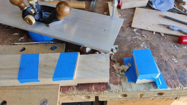
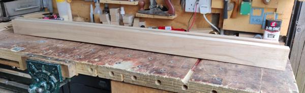
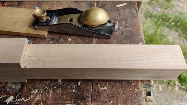
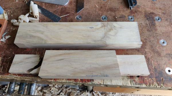
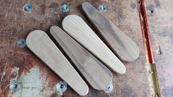
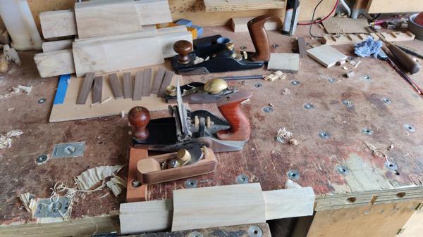
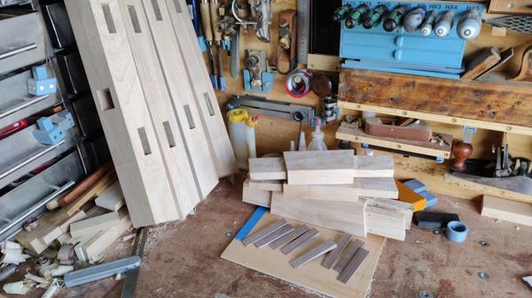
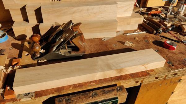
When I went back out to the garage, it still felt a bit early to be hitting things with a mallet, so I got the thicknessed cross-pieces out and cleaned up the machined faces with a couple of hand planes (a Clifton #4½ set for moderate shaving and a Stanley #4 set for a very light one):
2025-07-13-05-planing-cross-pieces_600.jpg


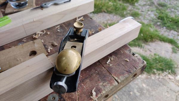
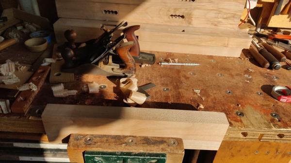
I then planed one edge square, using my Axminster #5 and a different Stanley #4. The reason for the different Stanley #4 was that I was finding some of the edges of these pieces had changeable grain and that #4 has a back bevel on the blade so cuts at a higher angle. The #5 left a bit of tear-out but was nice and quick to get the edges flat and square; the #4 sorted the tear-out.
2025-07-13-06-edge-planing_600.jpg


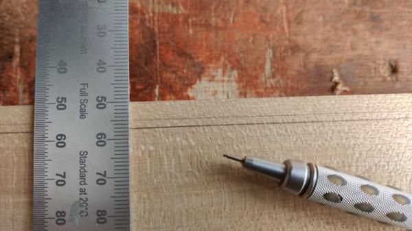
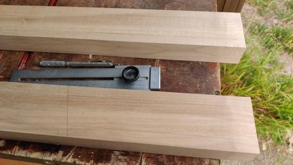
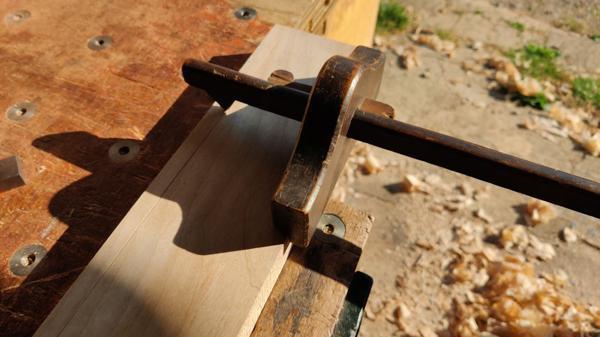
To sort the other edge, I used my panel gauge to scribe a line along both faces:
2025-07-13-07-panel-marking-gauge_600.jpg


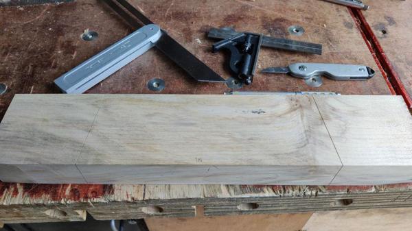
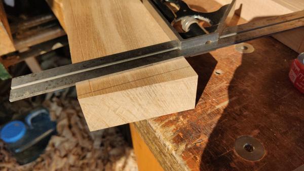
Before sawing to width, I also marked a square line on the ends that weren't square...
2025-07-13-08-marking-square-ends_600.jpg


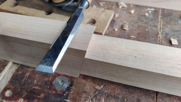
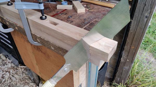
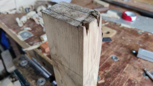
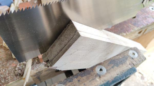
.. and then chopped the end off:

2025-07-13-09-sawn-off-square_600.jpg


The ends of the final pieces will get cut off at an angle rather than square, but having made the planks square-ended, I should be able to use the off-cuts as clamping blocks.

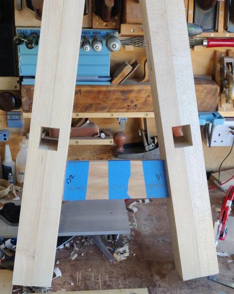
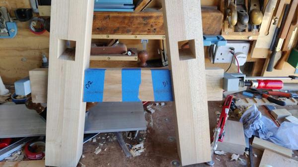
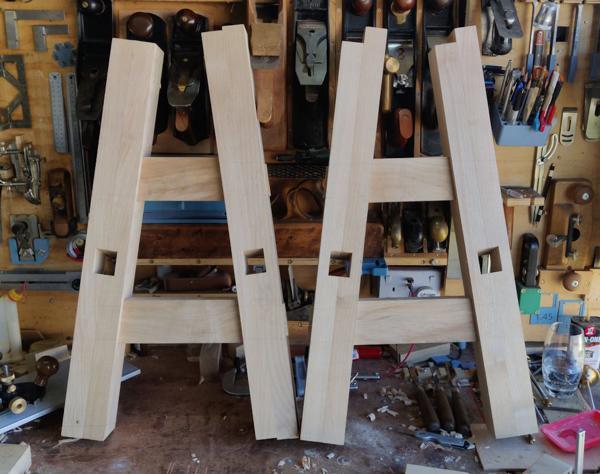
I then offered the legs I finished yesterday up to the cross-pieces and realised I'd made a mistake...

2025-07-13-10-offered-up_600.jpg


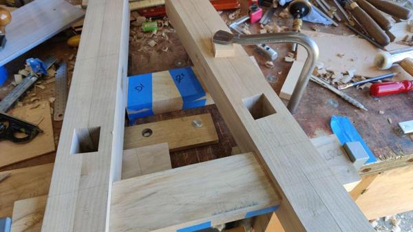
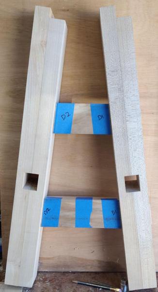
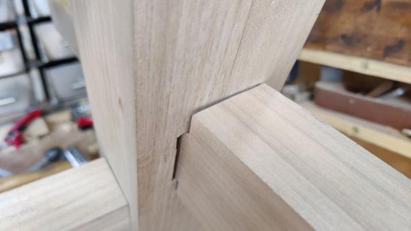
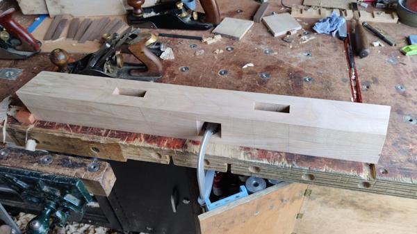
Somehow, I'd managed to mark (and chop) the cross-piece mortices at the wrong angle, so the face I'd selected as the inside face is now the outside face:
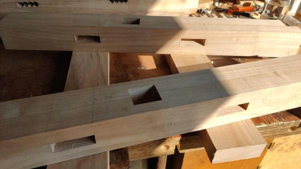
2025-07-13-11-inside-out_600.jpg


Thankfully, it's isn't a serious problem. I had to transfer the "wedge" markings round to the other side and the one with the incorrect wedge line will forever have that line, but it'll be hidden under the shoulder of the cross-piece so it doesn't matter. It also means that the positions of the cross-bars won't be quite the same as they were in the model, but I've updated the model to match reality and it still looks fine.

The only downside of the new positions is that the clearance above the cross-bars for a saw (being used through the gap between the two top pieces) will be slightly lower than designed (185 mm rather than 200 mm). If I decide that's an issue, I can always put a little notch in the top cross-bars, so I'm not going to worry about it for now.

Anyway, I got on with marking the cross-pieces to show where they'll be cut (to match the updated model!):
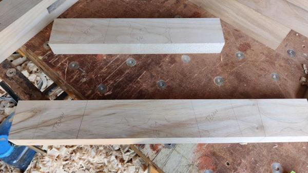
2025-07-13-12-marked-up-cross-pieces_600.jpg


There's a lot of excess on the bottom one; that's partly because I prepared them oversize, but also partly because I changed the splay angle to 8° instead of 15° and that brought the legs closer together at the bottom.

Having pencilled the marks in, I decided to bite the bullet and knife the tenon shoulders:
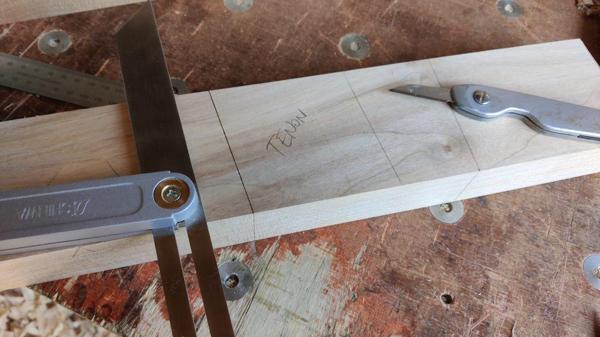
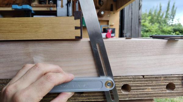
2025-07-13-13-swapped-sliding-bevel_600.jpg


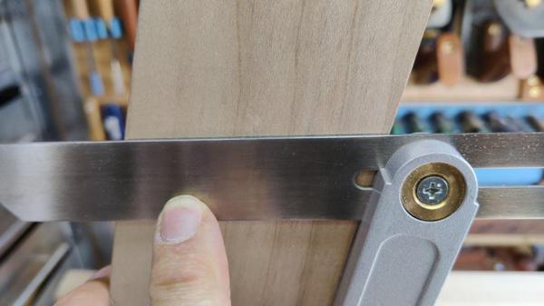
The most observant among you may have noticed that I've swapped to the Shinwa sliding bevel (which was previously set to the 15° angle for the stretchers). I had planned to use the Shinwa one for the stretchers (and leave it set) and the other one for these cross-bars, but I found the other one didn't seem to line up with some of the marks I'd previously made.

I've never had great results with the wooden-handled sliding bevel to be honest (that was part of the reason for buying the Shinwa one). I never understood why before, but today's confusion made me investigate properly. It turns out that the "stock" (wood/brass bit) of the other sliding bevel isn't straight (it's bowed along it's length) and also isn't parallel (one end is about 0.5 mm narrower than the other). I can probably sort it out with a lot of tedious work with sandpaper, but it's much too hot for that sort of thing, so I just decided to swap sliding bevel to the one I trust.

Before changing the angle on the Shinwa sliding bevel, I used it to knife a line on a bit of scrap. I should be able to use that bit of scrap to set the bevel back to the stretcher angle when I get to that stage.

Anyway, with both ends of the lower stretchers knifed all round the shoulders, I knifed round the shoulder on the upper ones too, but only on one end:
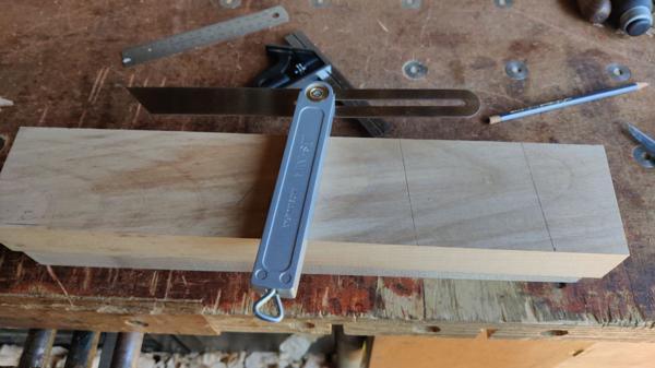
2025-07-13-14-only-one-end-marked_600.jpg


The other end will get marked up after assembling the legs to the lower cross-bar.

By this point, it was 10am and I felt it was probably reasonable to make a little bit of noise, so the mallet and chisels came out and I finished off the mortices in the last two legs:
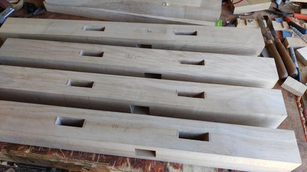
2025-07-13-15-finsihed-chopping-mortices_600.jpg


If I did those legs again, I'd be quite tempted to chop more of the mortices with the mortice chisel. I'm sure it's partly that I've done four in a row, but I was getting quite fed up with the long-winded tidying up process that follows drilling. At the moment, I feel I'd enjoy using the mortice chisel more, even though it would take longer. Of course if I did four in a row with a mortice chisel, I might be saying I'd do it with a drill next time!
 
Wouldn’t have any other than the Shinwa, just so easy to set, that’s a good point I hadn’t considered, if the shaft isn’t exactly parallel when you turn it over errors will occur, as opposed to purely Al made ones lol. Looking good, that’s going to be really sturdy.
 
With the mortices cut, I could get on with the tenons. For the first side of the first one, I decided to try cutting the tenon as a half-lap (with the to-be-off-cuts still in place on the ends of the cross-piece):

2025-07-13-16-cross-cutting-for-tenons_600.jpg


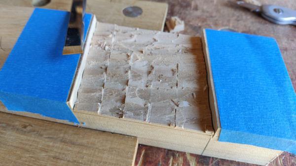
After sawing a few places across the bit to be cut out, I chiselled out the bulk of the waste:

2025-07-13-17-chiselled-out-waste_600.jpg


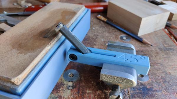
I fitted the biggest cutter to the router plane and started to cut, but it was leaving a pretty shabby finish, so I figured it was time for a quick sharpen:

2025-07-13-18-sharpening-router-plane-cutter_600.jpg


With that done, it cut much better and I could get on with cleaning up the tenon faces:

2025-07-13-19-routering_600.jpg


Unfortunately, I'd been a bit over-enthusiastic (or perhaps overly-inept) with the chiselling and the grain was quite steep in places, resulting in some bits breaking out deeper than I'd like:

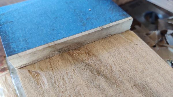
2025-07-13-20-break-out-near-outer-edge_600.jpg


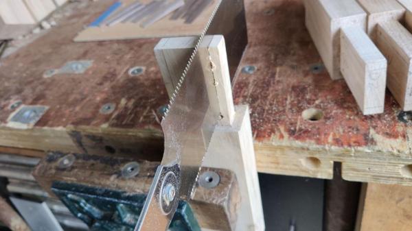
Although it doesn't look like it, that's the outer edge (the shoulder you can see is the bit that will be cut off), so there's a high chance it'll be visible on the outer edge of the joint when it's assembled. Feeling a little disheartened with that approach, I decided to cut the end off and saw off the waste for the other side:

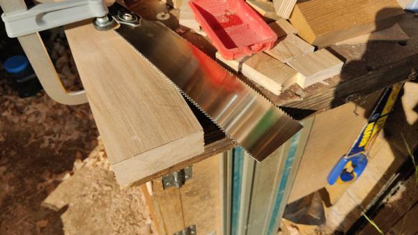
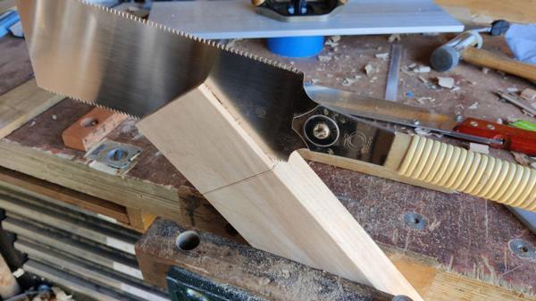
2025-07-13-21-sawing-other-end_600.jpg


That then got routered as well:

2025-07-13-22-more-routering_600.jpg


After checking and tweaking the fit for the outside of the mortice, it was time to cut the tenon down to width:

2025-07-13-23-cutting-sides_600.jpg


A little tweaking later and I could fit the first cross-piece to the two legs:

2025-07-13-24-lower-cross-piece-in-place_600.jpg


I'm much happier with that sawing-off technique so I'll do that for the rest.

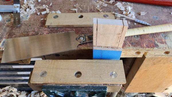
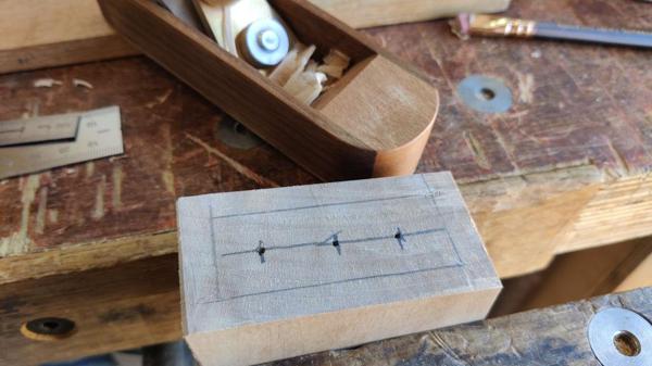
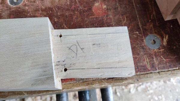
I want to use the off-cuts from the cross-pieces to help with clamping the leg frames together. As the tenons are currently over-length, the off-cuts need a little clearance. I took the cut-off end, planed it's face smooth and then marked an over-size rectangle on it, along with a few awl marks:

2025-07-13-25-planing-and-marking-dots-in-off-cut_600.jpg


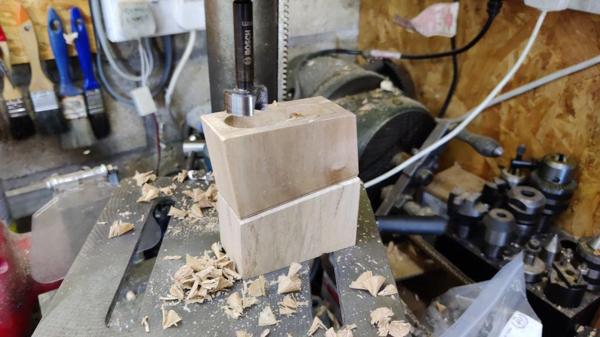
Mounting one on top of the other (so that the end face was parallel with the pillar drill table), I used a 24 mm Forstner bit to hog out the waste...

2025-07-13-26-forstner-drilling_600.jpg


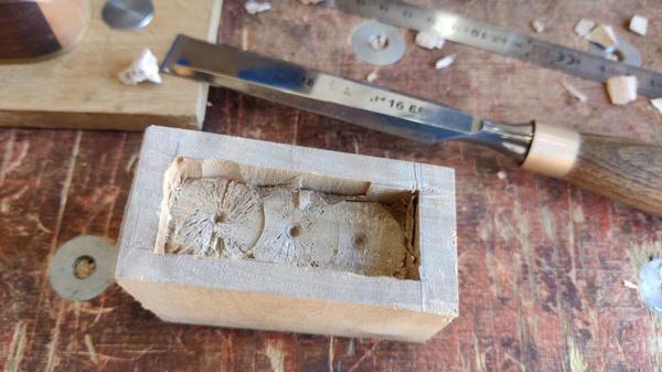
... then did some very rough chiselling to square the hole up:

2025-07-13-27-rough-chiselling_600.jpg


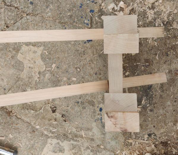
I could then do a quick test of clamping the legs to make sure the principle works:

2025-07-13-28-clamping-test_600.jpg


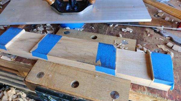
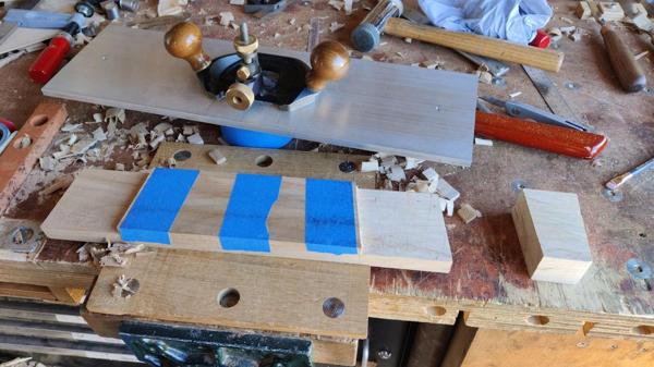
For the upper cross-bar, I went with the same process as before: sawing off the waste and then using the router plane to clean the faces up:

2025-07-13-29-routering-with-support-block_600.jpg


After fitting the first side of the tenon into one of the legs, I could mark the location of the bottom of the cross-bar and then disassemble it and clamp everything in place for marking the location of the other shoulder:

2025-07-13-30-clamped-for-marking-second-shoulder_600.jpg


I then did the same thing again (sawing tenon cheeks, chopping shoulders and router-planing faces) on the other end of that cross-bar. That went fairly smoothly and quickly and I could then dry-assemble the first leg frame, which felt like quite a land-mark:

2025-07-13-31-first-leg-fitted-today_600.jpg


By then it was 5pm and I'd been in the workshop on-and-off since 4.30am so I decided it was a good time to call it a day.
 
I was away last weekend (motorcycling around the north Cotswolds) and haven't had much oomph during the weekday evenings, but today I managed to get back out to the workshop for the afternoon and get on with the other leg frame.

I didn't take many photos; this was the only in-progress shot:

2025-07-25-01-in-progress-shot_600.jpg


However, it proceeded much as the previous one did, with the shoulders and cheeks cut roughly with the Ryoba and then the shoulders chiselled and the cheeks router planed smooth. At the end of the afternoon I had the second frame assembled (but not glued):

2025-07-25-02-second-leg-frame-done_600.jpg


They're far from finished, but that's still a big landmark. They need trimming to length (i.e. cutting the top and bottom off) and the mortices need widening at the outside so that the tenons in those little cross-bars can be wedged. For now though, they'll do and I'm going to work on the stretchers next.
 
This morning I got started on the work for the stretchers. A few weeks ago when I was cutting the (split) mortices for the stretchers, I got the stretcher planks out and noticed that they'd bowed slightly since being chopped up with the tracksaw. I drew a straight line near the edge so that I could work out how wide they would be (and hence work out the size of the mortices). You can see the bow here hopefully:

2025-07-26-01-bowed-stretchers_600.jpg


When I got them out this morning, I found that the straight line I'd drawn was no longer straight! They've obviously bowed a bit more in the last few weeks. You can perhaps see that in the next photo: the faint line is the previous pencil line (which goes corner-to-corner; this is the mid-point) and the darker line is a new one:

2025-07-26-02-moved-in-two-weeks_600.jpg


Thankfully the difference is quite small: they'll end up about 73 mm instead of the expected 75 mm. There should still be plenty of width for a decent shoulder I think. To get rid of the bow, I got the tracksaw out again:

2025-07-26-03-tracksawing_600.jpg


The edges then got planed square to the face side:

2025-07-26-04-planing_600.jpg


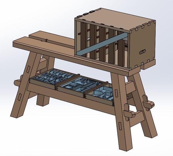
I'd like to be able to (temporarily) store three of the drawers on the stretchers (with some little brackets to stop them falling off), as shown in this CAD model screenshot:

2025-07-26-05-storing-drawers-cad-model_600.jpg


For that to be possible, gap between the legs at the top of the stretcher needs to be longer than three drawers. I got the three biggest drawers out and lay them on the stretchers with some spacers in between and with the drawer fronts (which are the highest bits) facing out:

2025-07-26-06-drawers-spaced-apart-with-front-out_600.jpg


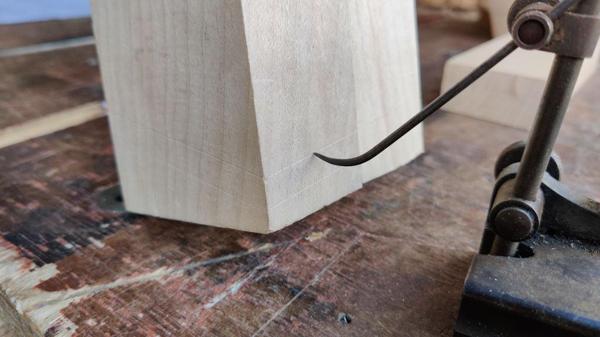
I then used the sliding bevel (reset for the 15° angle of the leg frames) to mark where the legs would sit:

2025-07-26-07-pencil-marking-length_600.jpg


As an alternative, I turned the drawers round so that the (lower) backs were facing out and I removed the spacers:

2025-07-26-08-drawers-close-together-with-fronts-facing-in_600.jpg


That gave me two pencil marks at each end of the stretchers and I could see what the difference was between the absolute minimum length for the drawers to fit and a length that would be very comfortable:

2025-07-26-09-pencil-marks-showing-difference_600.jpg


The measurements (at the top of the stretcher) came out as 886 mm and 915 mm. After a quick retreat to the CAD model, I settled on 910 mm as looking reasonable, so that's what I'll use.

The next job was to mark out the bare-faced tenons:

2025-07-26-10-marked-out-barefaced-tenons_600.jpg


I decided (as usual) to do one from start to finish and then work on the other three together. After a bit of pondering, I opted for the bandsaw to rough out the long cuts:

2025-07-26-11-bandsawing_600.jpg


The cross-cut Dozuki made light work of its job:

2025-07-26-12-cross-cutting_600.jpg


I then worked along the marking gauge line with an 18 mm chisel, coming in from the sides:

2025-07-26-13-chiselling_600.jpg


A smaller (12 mm) chisel sorted out the shoulders. The chiselling left a somewhat rough finish:

2025-07-26-14-chopped-shoulders-rough-finish-on-face_600.jpg


On the side where the grain resulted in a planing direction towards the shoulder, I did as much as I could with a block plane:

2025-07-26-15-block-plane-with-grain_600.jpg


Then tidied up the end a bit with a chisel:

2025-07-26-16-end-with-chisel_600.jpg


For the other side, I had to use the block plane at a jaunty angle:

2025-07-26-17-block-plane-against-grain_600.jpg


At this point, the tenon was the right height, but a bit too wide to fit in the mortice, so it was time for a bit of attention with a couple of planes (#5½ and #4½) to bring the board width down to be a nice sliding fit in the mortice and I could then do a test fit:

2025-07-26-18-test-fit-1_600.jpg


The tenon will get shortened quite a bit in due course, but I'll do that after cutting the mortice for the wedge.

Shoulder:

2025-07-26-19-test-fit-2_600.jpg


Now I've got three more to do, so that should keep me occupied for the afternoon.
 
It was all going so well... or so I thought.

This afternoon I got on with the other tenons. For the first one, I'd picked the biggest mortice (there's not much difference, but there is a little) and sized the tenon to suit that. I used the same mortice as the reference for all the other tenons.

Once the tenons were all a nice fit in that first mortice, I went round all the other mortices and tweaked them until all the tenons fit in all the mortices. These stretchers are designed to be removable and I figured it would make life easier if I could fit any stretcher in any location.

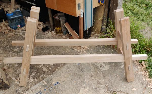
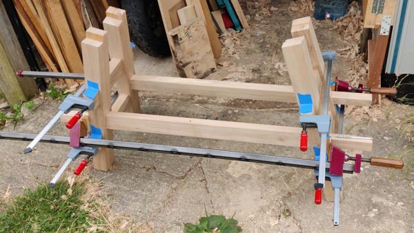
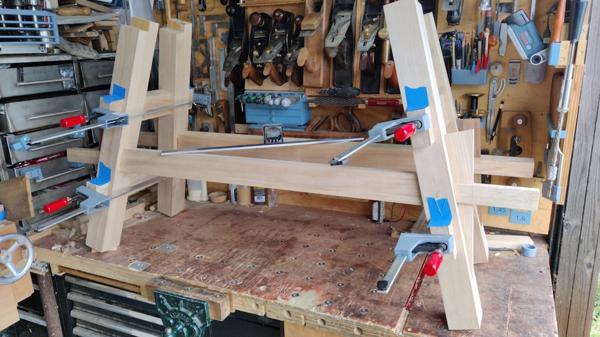
With that done, I could assemble the base:

2027-07-26-20-fits-together_600.jpg


You'd think I'd be feeling positive about that, wouldn't you? Sadly not. Getting that together involved a heck of a lot of mallet-based persuasion. I probably shouldn't have bothered as I knew it was going to be difficult to put it together as soon as I started. I put the two stretchers into the holes in one leg frame, then offered up the other one:

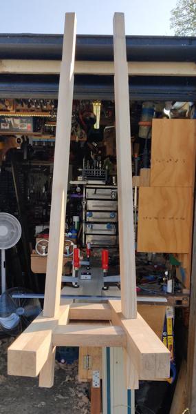
2027-07-26-21-thats-not-right_600.jpg


That's not how it's supposed to look. Here's another view with the two stretchers fitted into one of the leg frames:

2027-07-26-22-two-degrees_600.jpg


Each stretcher tapers in at about 2°. That's not a huge angle, but over a metre it adds up to about 36 mm, so the gap between the two stretchers is 72 mm narrower at the other end.

At the moment, I haven't managed to figure out why that's happened. I've checked all the mortice sockets and they're square to the inside faces. I've also checked that the inside face of one leg is coplanar with the inside face of the other. In my head, that should mean that the stretchers (which I don't think are substantially bowed) come out square to the inside face. I guess 2° isn't that much so I might not be seeing that error over the short distances I'm measuring when I'm checking the mortices, but that's my only thought so far.

I was feeling a bit hot and a lot bothered so I decided to have a rest (for "have a rest" read "help Carolyn with some jobs") and see if I can make more sense of it later.
 
Are you sure this is still a piece of workshop kit? The attention to detail and care in execution look more like something for the parlour!
 
Are you sure this is still a piece of workshop kit? The attention to detail and care in execution look more like something for the parlour!

If the attention to detail were that good, it would fit together! 😭

Also, it would have fewer dents as I might not have dropped it quite as many times as I have. ;)
 
Well, I think I'm beginning to get an idea of what's going on. I still haven't got my head round why, let alone what to do about it, but at least it's a step in the right direction.

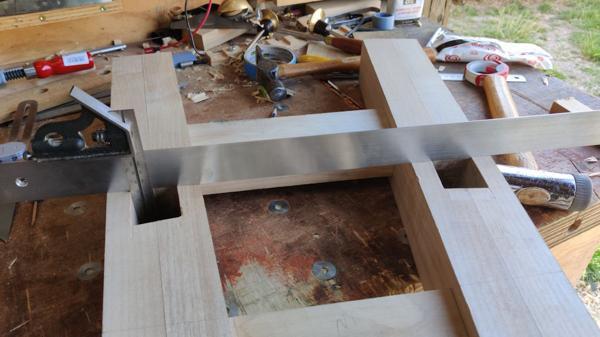
I started by putting a straight edge across the face of the leg and using a small combination square to check the mortices:

2025-07-26-23-checking-square-mortices_600.jpg


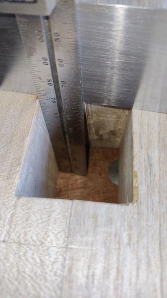
They look pretty square to me:

2025-07-26-24-mortices-square_600.jpg


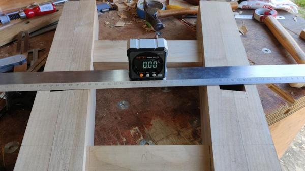
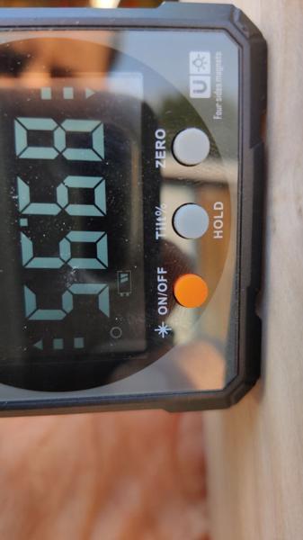
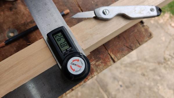
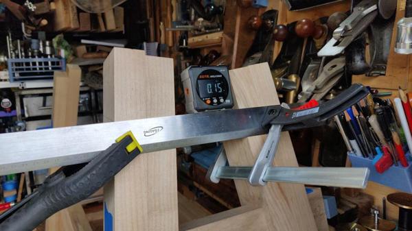
I then put the straight edge flat on the leg and put a digital angle gauge on it. I could then zero the angle gauge so the leg face became a reference:

2025-07-26-25-zeroing-angle-gauge_600.jpg


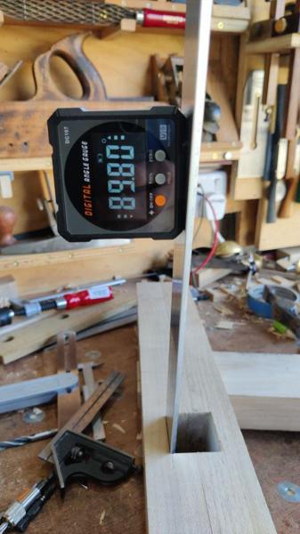
The straight edge then got shoved in the mortice and I could use the angle gauge to check the angle:

2025-07-26-26-still-think-thats-square_600.jpg


I would consider 89.80° close enough to square!

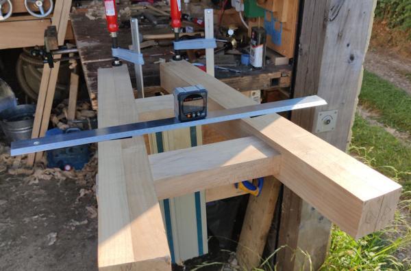
It then felt like a good idea to try using the real stretchers, so I clamped them to the very end of the bench and again zeroed the angle gauge:

2025-07-26-27-set-up-for-using-real-stretchers_600.jpg


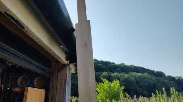
Unfortunately, when I tried to fit the stretchers, they hit the gutter: the leg frames aren't sticking out of the garage enough:

2025-07-26-28-not-enough-clearance_600.jpg


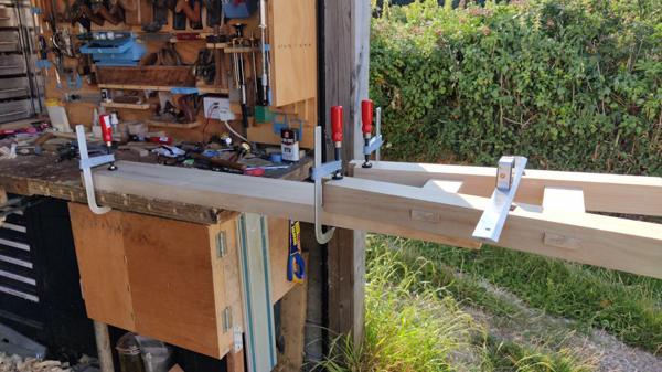
To sort that out, I used one of the pieces that will eventually become the top of the bench to extend the bench out further:

2025-07-26-29-bench-top-came-in-handy_600.jpg


I could then measure the angle on the side of the stretcher:

2025-07-26-30-measuring-stretcher-angle_600.jpg


I don't think anyone could argue with 89.95°!

However, if they're square, why are they wonky?

2025-07-26-31-square-but-wonky_600.jpg


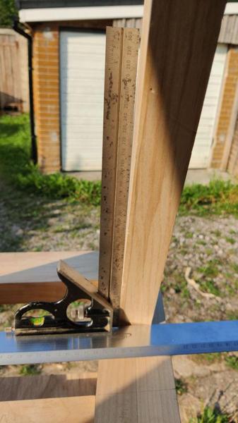
As another test, I clamped the straight edge to the leg face and used a combination square to check the angle of the stretcher. Bizarrely, it showed the stretcher leaning outwards:

2025-07-26-32-using-combination-square-bending-outwards_600.jpg


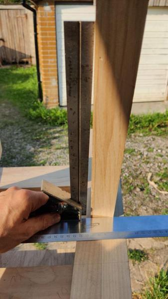
I then had a moment of inspiration and leant the combination square forward so that its rule is parallel with the angled stretcher. Lo and behold...

2025-07-26-33-leaning-combination-square-bending-inwards_600.jpg


... that makes it look like its leaning in.

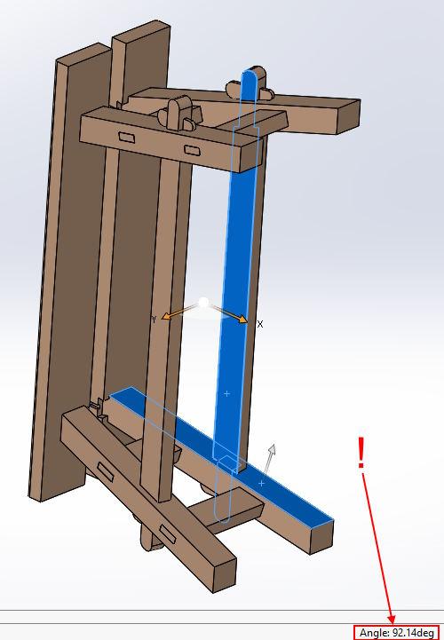
I think I'm suffering from some sort of compound angle complication. I haven't got my head round it, but I thought it would be a good idea to ask Solidworks what it thought the angle between the two faces should be:

2025-07-26-34-cad-model-92-degrees.jpg


If you recall my last post, I said the stretchers were leaning it at about 2°. The CAD model says they should be at 92.14°, so if they're at 90° that would explain the 2° error I think.

I still don't really understand it, but at least things are starting to tally with each other, so that's something.

At the moment, the only thing I can think of to do about it is to open up the mortices (and ruin the lovely finish I got from the router plane). That'll leave a very sloppy mortice, although I could potentially fit some wedges to close the gap up again.

It's time for a commiserating pint of Timothy Taylor's Dark Landlord I think.
 
No, there’s no reason that I could imagine where they wouldn’t be at 90, Solidworks? It’s wrong! I would think it’s just a little error on each that adds up.
Me? I would just pull them over and put them into the mortices at the other end, have you tried pulling them apart? Bet they’ll go.
 
No, there’s no reason that I could imagine where they wouldn’t be at 90, Solidworks? It’s wrong! I would think it’s just a little error on each that adds up.

But where's the error? 4° total error should be visible somewhere! The only way I can find it is if I lean the square over. To say I'm confused is an understatement.

The beer's nice though!

Me? I would just pull them over and put them into the mortices at the other end, have you tried pulling them apart? Bet they’ll go.
They did. That's how I got it together for the first photo in this post. However, it took a heck of a lot of hard whacking with a mallet. It then took even more hard whacking to get it apart.

Given that the bench is intended to be dismantle-able for transit, that's not really viable: I need to do something about it.
 
Well in that case, you will have to make the mortices wider but only do it on the faces facing the middle so that the discrepancy will be hidden by the shoulder.
Question, do they fit reasonably on an individual basis? If not that’s where to start.
Just a thought Is the material you made the legs from properly square?
 
Well in that case, you will have to make the mortices wider but only do it on the faces facing the middle so that the discrepancy will be hidden by the shoulder.

Yes, I think that's probably what I'll have to do. I'll open them up on the outside edge on the inside face. I'll then add a wedge on the inside edge of the inside face. Hopefully it'll end up looking okay.

Question, do they fit reasonably on an individual basis? If not that’s where to start.

Yes, they're a reasonably snug fit, especially left-to-right. There's a bit of wiggle room up and down, but that wouldn't affect this angle.

Just a thought Is the material you made the legs from properly square?

I think so (and certainly not 2° out). The only face that matters is the inside face. If the one with the cross-bars was out of square then the cross-bars would cause the face to be wonky, but that would show up with a straight edge across it.
 
Yesterday evening, while I was sipping gently at a small glass of some wonderful stuff from Campbeltown, it finally clicked: it is definitely a compound angle issue.

The leg frames sit at 15° off vertical. The stretchers are horizontal and hence the angle between the top of a stretcher and the leg is 85°. If you were to gradually decrease that 85° angle, the stretchers would eventually become parallel to the leg frames. At that point, the stretchers would be leaning in towards each other at 8° (16° included angle) just as the legs are.

Thinking of it like that, it's inevitable that with a bit of lean angle (15°) there would be a proportion of that 8° angle present in the stretchers and that's what I should have compensated for (by angling the mortices).

Today I'll try to adjust that angle (by opening up one side and then making a wedge to glue in on the other side).
 
The complexities of compound angles confuse a lot of people, me included.

I've read descriptions of how to build a pair of trestles which many carpenters were expected to understand. It used a method of laying out the joints (lap joints I think) so that the angles for the splayed legs were correct, with no degree measurement, calculation or CAD magic. Apparently it was also a good intro to angled cuts in roofing.

So it's interesting to see an engineer's approach to this sort of thing.

I reckon that if you are planning to add a gothic turret to your house some time soon, you'll be able to do so! :)
 
I've read descriptions of how to build a pair of trestles which many carpenters were expected to understand. It used a method of laying out the joints (lap joints I think) so that the angles for the splayed legs were correct, with no degree measurement, calculation or CAD magic. Apparently it was also a good intro to angled cuts in roofing.

I have to say I'm slightly in awe!

I think of myself as being relatively good at geometry & thinking in 3D so I am rather annoyed at myself for having missed this. If it had occurred to me that it was a problem (and why) I could probably have done several pages of unnecessarily-complicated trigonometry to figure out the angle, but I didn't realise the angle even a thing until yesterday evening (and CAD is easier & makes me lazy).

Being able to lay it out in a simple way (as per your description) is all the more impressive given how complicated I would have made it!
 
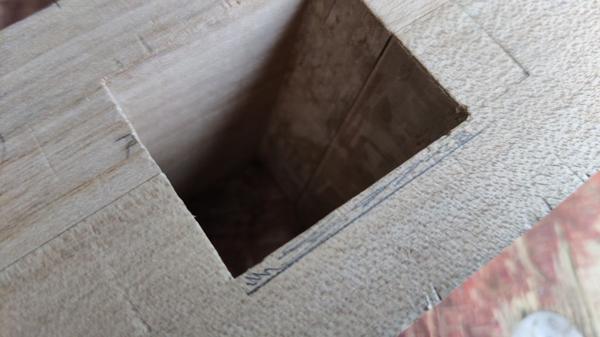
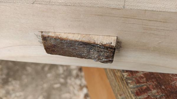
With everything now a bit better understood, I was feeling much more comfortable about what I had to fix. This is the bit (on the outside edge of the inside face) I needed to remove from each leg to expand the mortice:

2025-07-27-01-the-bit-i-need-to-remove_600.jpg


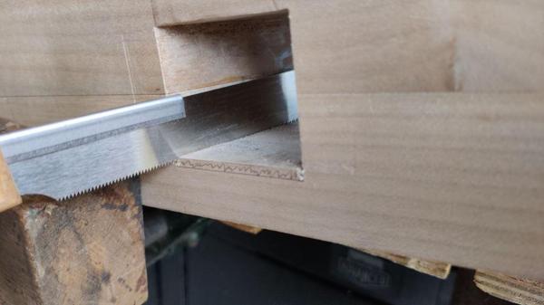
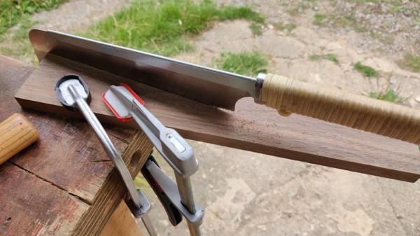
I started by cutting the ends of that wedge with a little flush-cut saw, just to avoid any risk of splits propagating further than I'd want them to:

2025-07-27-02-flush-cut-saw_600.jpg


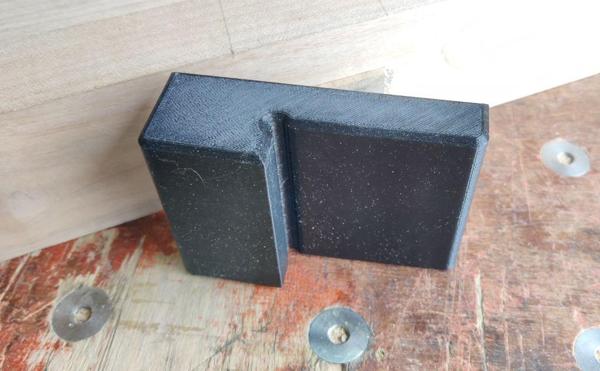
Overnight, the 3D-printer had been hard at work making the Cock-Up Fixer 2000™:

2025-07-27-03-3d-printed-fixer_600.jpg


That got clamped in place on the side of each leg:

2025-07-27-04-clamped-in-place_600.jpg


The edge is positioned just in the right place for the new angled mortice and the face at the top is angled at 2.14° from vertical so that it can be used as a reference to guide the chisel (after a couple of intermediate cuts to get rid of most of the waste):

2025-07-27-05-guiding-chisel_600.jpg


I was really pleased with the finish after paring; it's almost as good as the router plane finish:

2025-07-27-06-good-finish_600.jpg


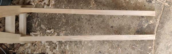
After expanding the mortices in the first leg frame, I fitted the stretchers to see how it looks. They look much closer to parallel now:

2025-07-27-07-first-two-looking-promising_600.jpg


This also showed something I was expecting: the angle of the shoulder on the stretchers will also need adjusting:

2025-07-27-08-angle-needs-adjusting_600.jpg


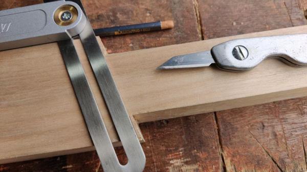
I checked the CAD model and it reported the angle as 92.21° (so slightly different to the mortice angle, which was 92.14°). I doubt that 0.07° difference is going to affect anything (as if I could cut that accurately anyway!) but I went for 92.2° rather than 92.1° anyway. To mark it up, I used a digital angle gauge on the top edge:

2025-07-27-09-digital-angle-gauge_600.jpg


The marks got transferred down the side with the sliding bevel:

2025-07-27-10-transferring-marks-round_600.jpg


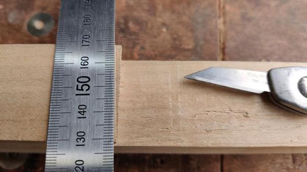
This time I used a rule to "join the dots" on the bottom edge as the digital angle gauge only sticks out one way and hence it would need to be re-set to a different setting for this side.

2025-07-27-11-rule-on-bottom_600.jpg


It was then simply a case of chiselling to the line:

2025-07-27-12-chiselling_600.jpg


I was very, very pleased that with all the mortices expanded and the stretcher shoulders adjusted, the frame slid together very smoothly and easily:

2025-07-27-13-finally-together-easily_600.jpg


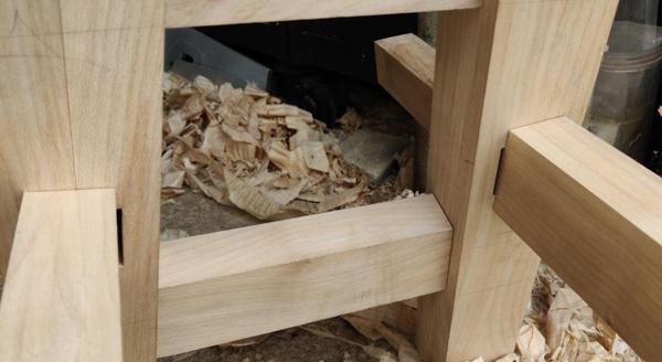
You can see the gaps that are now present on the inside edge of the inside face as a result of opening out the outside edge:

2025-07-27-14-gaps_600.jpg


I'll probably insert some little wedges into those gaps to fill them up (once I've figured out a way to make wedges), but I don't see at as urgent (or even that important): the shoulders are doing the work of holding it together and the sides of the mortice shouldn't really matter (as there's no glue). Having them open as they are makes it easier to put the frame together and take it apart again.

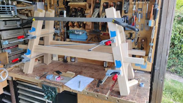
I think the next job is to get everything clamped together fairly rigidly and then mark the locations for the mortices that will hold wedges to keep the stretchers in place.
 
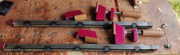
When I made some bar clamps a few years ago, I made them dismantle-able:

2025-07-27-15-dismantled-bar-clamp_600.jpg


I also made some much longer bars for when I needed to clamp long stuff (I also made it possible to join multiple bars for really long stuff). I've never had to use the longest bars until today:

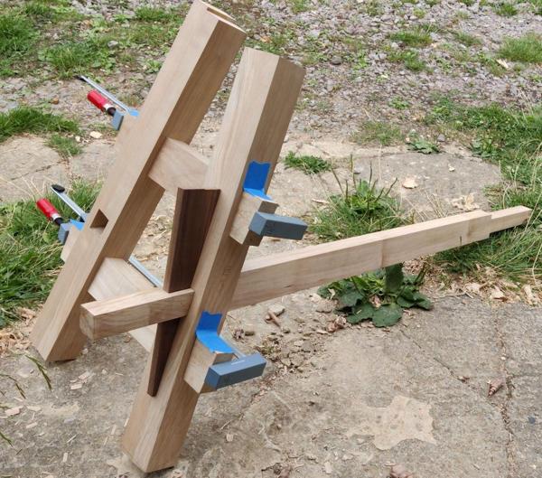
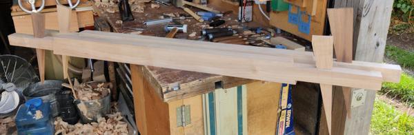
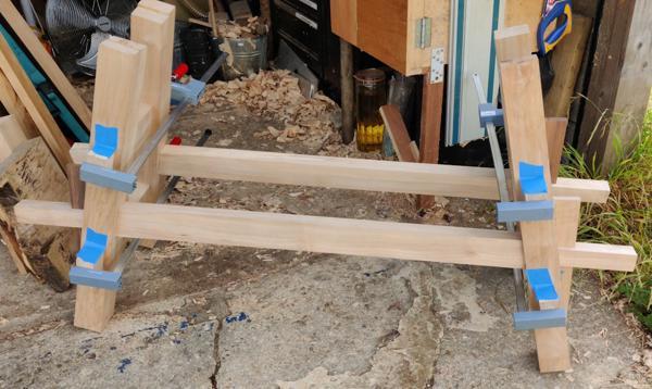
2025-07-27-16-clamped-frame-together_600.jpg


With the frame clamped together like that, I could draw a pencil line showing where the mortice needs to start:

2025-07-27-17-pencil-line-for-inner-extreme-of-mortice_600.jpg


It'll need a bit of extra clearance (so I'm clamping onto the leg, not just wedging into the mortice), but it seemed easier to start with that mark. I marked out what seemed like a sensible size mortice, with a 10° angle between the two sides of the mortice:

2025-07-27-18-marked-out-mortice-10-degrees_600.jpg


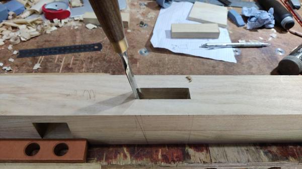
It was then time to start chopping with a 10 mm mortice chisel (and a conveniently sized support block under the tenon so I wasn't chiselling over air):

2025-07-27-19-starting-chopping_600.jpg


A bit further through the chopping:

2025-07-27-20-more-chopping_600.jpg


I went a bit over half-way through, then flipped it over and came in from the other side. Once the basic shape was roughed out, I marked a line a millimetre from the edge to expand the mortice so that the wedge does its job properly:

2025-07-27-21-expanding-for-clearance_600.jpg


I later went back and made that 2 mm to be on the safe side. With everything else done on the mortice, the last thing to do was pare the sides, for which I'd conveniently printed another paring guide:

2025-07-27-22-paring-with-guide_600.jpg


The actual width of the mortice isn't that important and it wouldn't be the end of the world if the sides aren't perfectly parallel, so I think it's fine to reference off the two different faces for the paring cuts. Using the paring block leaves a nice smooth finish on the sides.

With that, the first mortice was done:

2025-07-27-23-mortice-done_600.jpg


After taking that photo I noticed the little sticking out bit in the top-right, so I re-fitted the paring guide and sorted that out.

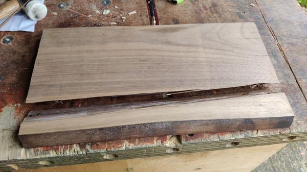
I haven't decided what wood to use for the wedges, although it'll probably be Sycamore. The off-cuts from cutting the stretcher tenons are a bit thin, and I don't have any other bits of Sycamore close to the right thickness so for now I rummaged around in the drawer and found a bit of American Black Walnut. That got Dozuki'd in half:

2025-07-27-24-chopping-bit-of-walnut_600.jpg


I really love the smell of ABW...

Once it was chopped at the right angle, I planed the faces to get it to the right thickness and then planed the edges approximately at the 92.2° angle of the leg-stretcher interface. Once that was done, I could do a trial fit:

2025-07-27-25-trial-fit_600.jpg


To say the wedge is a bit over-size at the moment would be a bit of an understatement, but it was really just for testing. It seems very rigidly held together, which is good. The wedge also came out with a few mallet taps and then the stretcher came back out easily so that's all looking promising.

Three more to go!
 
Just to continue the digression a moment, while it's fascinating to follow Al's problem solving approach to the geometry of compound angles, I just noticed this blog post from Mortise and Tenon Magazine.
It says that different countries have developed their own practical techniques for making complex structures in wood.

"The ancient art of stereotomy is a synthesis of geometry, craftsmanship, and cultural heritage. A highly developed method of laying out three dimensional objects in two dimensions and envisioning each element in a structure or piece of furniture without using any measurements, the practice has been utilized by multiple woodworking traditions over the centuries. "

 
Sounds really interesting, thanks Andy. I'd never heard of stereotomy, although having read the wikipedia page the concept is familiar enough.

That article sounds like it'd be worth a read.
 
This afternoon I got on with the other three mortices, which proceeded fairly rapidly so I could also make the other three wedges:

2025-08-01-01-four-mortices-and-wedges_600.jpg


You might notice that two of the wedges are American Black Walnut while the other two are Sycamore. That's a feature! If you cast your mind back to the débâcle with the compound angle, you'll remember that I had to adjust the angle of the mortice but also that another effect of the angle was a slight angle on the mortice for the wedge. That wedge angle is about 2° but is slanted one way on two legs and the other way on the other two legs. Having made the first wedge out of ABW for convenience, it occurred to me that I could use ABW for the wedges that slope one way and Sycamore for the wedges that slope the other and it would be a nice easy way to tell them apart.

The wedges still need shaping, but I couldn't resist a trial assembly (even though the sharp tips on the wedges might make it slightly more awkward to get it apart this time!)

2025-08-01-02-trial-assembly_600.jpg


The next job is probably to shape the wedges, or possibly to cut the top and bottom ends of the legs off. I'm not completely finished with mortising as I still need to open up the cross-bar mortices (for the wedges that will hold those tenons permanently in place), but I'm going to leave that until after I've done the joinery for the top.

I'm still a little undecided about the joinery for the top. I'm probably still leaning towards tapered sliding dovetails (with the taper tightening as planks for the top get closer together probably), but I'm definitely open to opinions or suggestions. Having the tapers going across means that, as the dovetails wear, the top planks will get a little closer together, which is probably fine. If I did them the other way round, then I'd need a big mortice in the top for the dovetails to drop into and as they wear, the planks will stick out at one end more than the other. It also strikes me as a nightmare to mark up and cut that way round (not that it seems easy to do it cross-ways!). Anyway, other suggestions (dovetail-y or otherwise) welcome!
 
I should have quit for the day while I was ahead. The latter half of the afternoon has not gone well.

I started by lifting the bench-to-be up onto my bench and using some wedges, straight edges and a digital angle gauge to get it level in both axis:

2025-08-01-03-levelled-on-bench_600.jpg


I then used a machinists scribing block to scribe lines parallel to the bench top:

2025-08-01-04-scribing-lines_600.jpg


The upper line will be the bottom of the leg. The lower line was the original plan for the bottom of the leg but when I did one of the other legs I found I was scribing into air, so I moved the line up a bit and tried again.

I could then mark the position of the underside of the top (which will become a shoulder line if I do a sliding dovetail) using a metre rule and the angle gauge:

2025-08-01-05-marking-top-with-rule-and-level_600.jpg


A quick sanity check with the sliding bevel showed the angle was what I expected:

2025-08-01-06-angle-sanity-check_600.jpg


The line got transferred around the ends in much the same way...

2025-08-01-07-marking-round-ends_600.jpg


... and then I "joined the dots" for the line on the least accessible edge. Next, I added a second line parallel to the first but about 20 mm higher. If I do tapered sliding dovetails, that'll be the top of the dovetail.

...

...

...

With all that marked up, I decided to disassemble everything to make the legs a bit easier to work on. That was mostly going very smoothly until:

2025-08-01-08-swearing-time_600.jpg


"Fiddlesticks", quoth he.

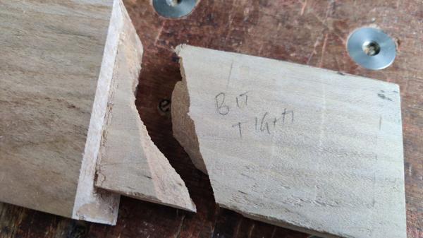
With the benefit of hindsight, I should have knocked each tenon out from the end, rather than supporting one leg and tapping the other to pull them apart. I also should have paid more attention to the note I wrote on that tenon:

2025-08-01-09-should-have-done-something-about-that_600.jpg


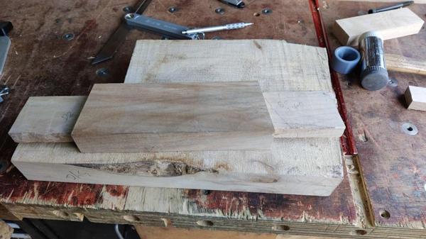
Working on the assumption that there's not much I can do to repair that (I'd wholeheartedly welcome opinions to the contrary!), I had a look round the remaining Sycamore and this was the only piece I've got left that is (barely) big enough to remake that piece:

2025-08-01-10-the-only-big-enough-bit_600.jpg


A bit of bandsawing and a lot of hand planing later and I've got it down to roughly the right size:

2025-08-01-11-hand-planed-to-rough-size_600.jpg


That knot you can see will be on the top edge (although it's not obvious in the picture, the new piece is only long enough at the bottom edge). I was unrealistically optimistically hoping it would get cut/planed away when I trimmed the off-cut down but alas it's there to stay. It'll end up a few millimetres inside the shoulder line.

Anyway, after I'd paid a small penance by hand planing that bit of sycamore, I decided it was sensible to stop before I did anything else stupid. I probably won't make it into the workshop tomorrow as as result of other commitments, so Sunday will have to be the day for remaking the cross-piece (unless anyone suggests a miracle way of repairing that broken piece).

That's it for today, I'm off to cry over a pint of Brains Dark.
 
That's a shame! Sometimes you can clear out the mortise and also cut away the rail, then insert a loose tenon. But on this, the tenon is nearly as big as the rail, so I don't think that would work.
Another alternative sometimes is to use dowels instead, but that's not as strong.

So I think a new piece is the best plan, even if the wood is B-grade or needs some extra bits glued on here and there.
 
The forecast is predicting rain around lunchtime today, so I thought I'd postpone making the new cross-bar and get on with a couple of jobs that are easier with the garage door open and stuff hanging out the end. First of all, I chopped the top and bottom of all the legs off using the big Ryoba and bravely cutting to the line:

2025-08-03-01-sawing-legs-to-length_600.jpg


Having done the top as well as the bottom, I'm now committed to some sort of joinery that takes up no more than 20 mm of the top of the leg, but I don't think that's too restrictive (and a dovetail of that size seems plenty big enough to me).

Next up, I marked up all the wedges:

2025-08-03-02-marked-up-wedges_600.jpg


They got rough sawn to shape with a cross-cut Dozuki:

2025-08-03-03-sawing-wedges-roughly_600.jpg


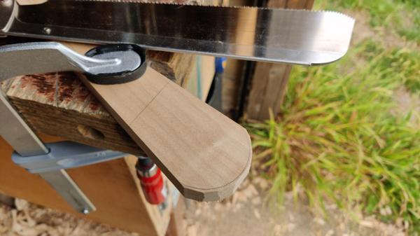
I used my home-made block plane to shape the ends round-ish:

2025-08-03-04-planing-round-ish_600.jpg


On one of them I did that with a spokeshave, but I found the block plane much easier to work with and ended up only using the spokeshave for chamfering the ends:

2025-08-03-05-spokeshave-for-chamfer_600.jpg


Four wedges complete:

2025-08-03-06-four-wedges_600.jpg


For the replacement cross-bar, I transferred the shoulder lines across from the broken one and then marked all the way round with sliding bevel, square and knife:

2025-08-03-07-transferred-lines_600.jpg


This is what the rather rough end looks like:

2025-08-03-08-rough-end-ready-for-sawing_600.jpg


Most of the really rough bit is going to get removed.

Next up was sawing the cheeks...

2025-08-03-09-sawing-cheeks_600.jpg


... then cross-cutting a millimetre or so from the shoulder line with a Dozuki. Before starting to clean up the cheeks and shoulders, I thought I'd roughly pencil in the expected final shape of the tenon so I could see how much of that rough stuff was going to get removed:

2025-08-03-10-pencil-marks-to-get-an-idea-of-whats-going_600.jpg


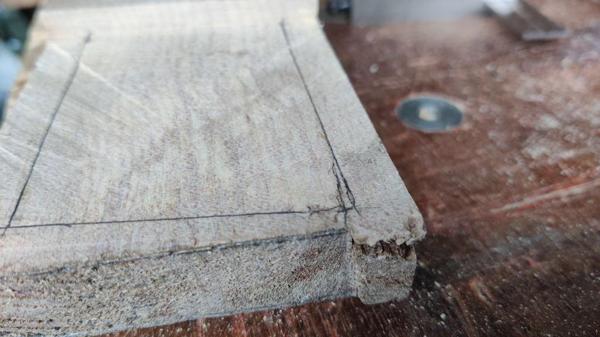
The little wobbly pencil line just inside the right-hand corner is what looks like a slight crack in the wood. I'm not too concerned about that at the moment as I can always bring the line in slightly and use a thicker wedge.

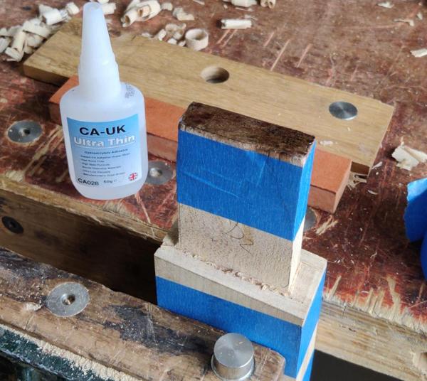
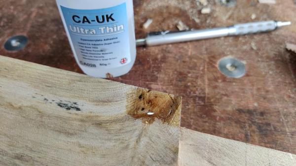
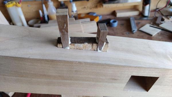
After I'd used a router plane to clean up the cheeks and a chisel to sort the shoulders out, I accidentally knocked the end of the tenon against something and a little piece broke off in the corner. I (medium viscosity) superglued that back on again (you can just about see the faint diagonal line of the join under the masking tape in the next photo) and then I figured I'd pour a bit of ultra thin superglue into the end grain just because I figured it couldn't hurt:

2025-08-03-11-thin-superglue-into-end_600.jpg


While I was at it, I poured a bit into the knot as well:

2025-08-03-12-thin-superglue-into-knot_600.jpg


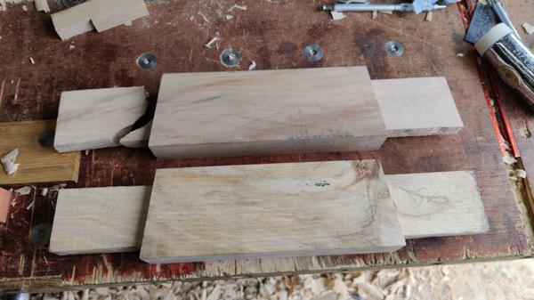
Old and new next to one another:

2025-08-03-13-old-and-new_600.jpg


This is the bit (from the rough end) that'll get chopped off (flush with the leg) after it's wedged and glued in:

2025-08-03-14-the-bit-that-will-get-cut-off_600.jpg


I think that gets rid of most of the shabby wood so I'm hoping I'm going to get away with using this piece!
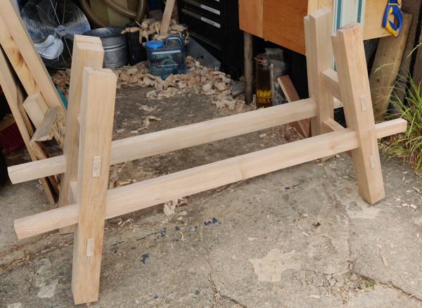
I'd been planning to cut the sliding dovetails (or whatever joint I finally decide on for the top) before assembling the leg frames, but after the incident with the cross-bar, I'm feeling quite keen to get the leg frames assembled and glued together for good. To do that I need to open up the mortices in the legs and then give the internal leg faces and the external cross-bar faces a once over with a smoothing plane as that won't be possible again after assembly. I also need to make the wedges and cut the slots in the tenons.

Time for a cup of tea first.
 
When this is finished, ordinary people will just see a well made bench.

You will remember all the thought, care and emotion behind it!

Good recovery.
 
When this is finished, ordinary people will just see a well made bench.

You will remember all the thought, care and emotion behind it!

Good recovery.
Thanks Andy. I'm hoping you're right about the "well made" bit. Until I've done the dovetails I'm going to remain sceptical!

I'll certainly remember the emotion :ROFLMAO:
 
I'm beginning to think that either this project is cursed or perhaps I'm just not very good at this woodworking malarkey.

The next job after the break was to mark up the shape of the gaps for the wedges. I, rather arbitrarily, went for a 6 mm increase in mortice width at the outside, just because it felt like a reasonable proportion of the mortice length.

2025-08-03-15-marked-up-wedge-gaps_600.jpg


I also marked pencil lines on the sides to show the angle I needed to chop at:

2025-08-03-16-pencil-marks-for-sighting_600.jpg


To remove the waste, I started with a 10 mm mortice chisel to get rid of most of the waste...

2025-08-03-17-mortice-chisel-for-roughing_600.jpg


... and then a bevel-edge chisel for the final cuts:

2025-08-03-18-bevel-chisel-for-finishing_600.jpg


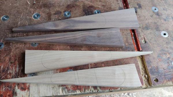
For the wedges, I found a bit of American Black Walnut that was only a little bit thicker than required. It had a bit of a split in it, so I pulled it apart:

2025-08-03-19-split-bit-of-walnut_600.jpg


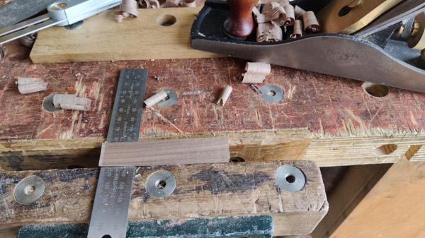
A bit of that (including the small split-off piece) got chopped up into wedges and the wedges got planed to thickness and to have smooth faces for gluing. The final planing cut was done with the thick end of the wedge clamped in the vice and the thin end supported on a steel rule:

2025-08-03-20-planing-wedges_600.jpg


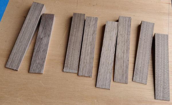
That gave me this pile of wedges, cut at about 6° (the angle of the extra bit I chiselled away worked out as 4.2°, but some of the tenons were a slightly loose fit along the long axis and I figured it's better to err on the side of a slightly too big angle):

2025-08-03-21-half-the-wedges-need-trimming_600.jpg


The eagle-eyed among you will spot that there are only half as many as I needed there, so I went back and made some more later. I also wanted to trim them a bit shorter (so they don't go all the way down into the slot but just far enough to firmly push the sides of the tenons apart. I did that on seven out of the eight wedges but somehow missed one and didn't notice.

Before gluing things together, I gave all the faces of the cross-pieces a once over with a scraper plane (some of them have slightly changeable grain) and chamfered the edges with the home-made block plane:

2025-08-03-22-finishing-all-surfaces_600.jpg


I then gave the inside face of all the legs a quick once over with a #4:

2025-08-03-23-smoothing-plane-legs_600.jpg


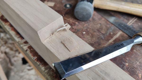
Before assembly, I also needed to make the slots for the wedges to go into, so I started by drilling a 4 mm hole near the bottom of the tenon...

2025-08-03-24-drilled-and-marked-for-cut_600.jpg


... and then used the Ryoba to saw down to the hole:

2025-08-03-25-sawing_600.jpg


Everything (except the other eight wedges and for the job of trimming the wedges a bit more) ready to go:

2025-08-03-26-ready-to-go_600.jpg


The first one went very smoothly I think:

2025-08-03-27-first-one-went-smoothly_600.jpg


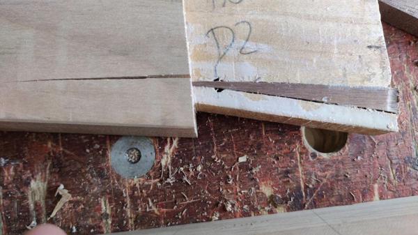
The second one did not. The wedge had a sharp end and it went a long way down into the tenon and split the cross-bar. It was surprising how easily it did so: I didn't feel like I was hitting it especially hard.

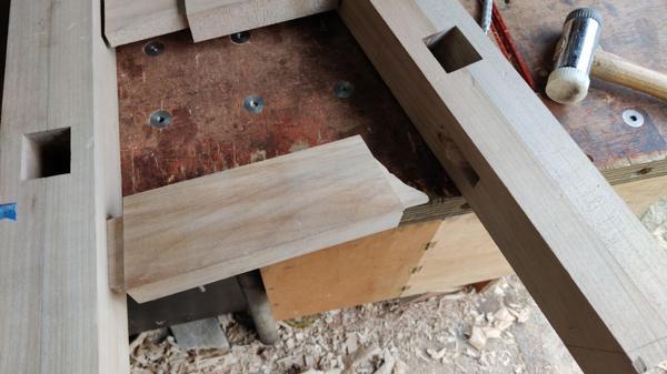
After I saw the crack, I then started hitting it a bit harder, but not on the wedge! It took quite a bit of frantic back-and-forth and the drilling out of one of the wedges to get the cross-bar back out of the leg, but thankfully it did come out with no major damage to the leg (just a bit of glue that'll need to be cleaned out of the mortice in due course):
2025-08-03-28-second-one-did-not_600.jpg


Much profanity ensued (again).

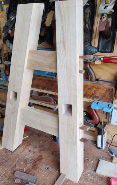
Rather than just throwing all of my toys out of the pram and storming off, I thought I'd get the other leg frame assembled (which thankfully went quite smoothly).

2025-08-03-29-one-frame-together_600.jpg


I don't have enough Sycamore to remake that cross-bar, so I'm going to have to go to a timber yard and buy some more before I can do much more. I will saw off the excess on the finished leg frame (and perhaps on the one finished joint on the other leg) tomorrow and see how it looks, but there's not a lot else I can do until I've bought more wood.

Maybe I should go back to exclusively doing metalwork: this wood stuff is much too difficult!
 
That's a shame, Dr. Al, that little hole was supposed to prevent exactly that. But I have no doubt that you will overcome.
If it's any consolation, just about every project I ever attempt has some such hiccup.
S
 
No, Al, just glue that up. It's not a structural; issue, and it will plane up invisibly. I've found over the years that if a wedge spilts a tenon and on into the body of the piece, like yours, that the wedge was probably too thin. Make a new one just a little bit fatter.
 
Looking at it mathematically:
1. You want 6mm of wedge showing at the face
2. You know the distance from the face to the stop-hole
3. You know the angle of the wedge.

So, make a new wedge, the same angle. Find the 6mm thickness position, measure back from that and trim the point off there. You may have to sharpen the first couple of mm to get the wedge back in.
Also, if it were me, I'd make those stop-holes a tad bigger.

Sorted :)
S
 
Speaking merely as an impartial observer, I believe that lively discussion about the best way to wedge M&T joints has been going on at least as long as there have been woodworking magazines or equivalent.

I expect that all methods are suitable in some circumstances. How do you know which circumstances? Try it and see!

By documenting all your projects you stand a good chance of learning from them. Those of us who are old enough to have forgotten more than we can remember will just look on enviously! ;)
 
No, Al, just glue that up. It's not a structural; issue, and it will plane up invisibly. I've found over the years that if a wedge spilts a tenon and on into the body of the piece, like yours, that the wedge was probably too thin. Make a new one just a little bit fatter.

Thanks Mike, I'll give it a go.
 
By documenting all your projects you stand a good chance of learning from them.

That's part of the reason I do it to be honest. There have been quite a few times I've gone back to read my old posts to remind myself how I did something.
 
Back
Top