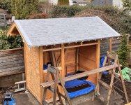
• Hi all and welcome to TheWoodHaven2 brought into the 21st Century, kicking and screaming! We all have Alasdair to thank for the vast bulk of the heavy lifting to get us here, no more so than me because he's taken away a huge burden of responsibility from my shoulders and brought us to this new shiny home, with all your previous content (hopefully) still intact! Please peruse and feed back. There is still plenty to do, like changing the colour scheme, adding the banner graphic, tweaking the odd setting here and there so I have added a new thread in the 'Technical Issues, Bugs and Feature Requests' forum for you to add any issues you find, any missing settings or just anything you'd like to see added/removed from the feature set that Xenforo offers. We will get to everything over the coming weeks so please be patient, but add anything at all to the thread I mention above and we promise to get to them over the next few days/weeks/months. In the meantime, please enjoy!

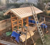
A Japanese style garden shed

Mike G said:
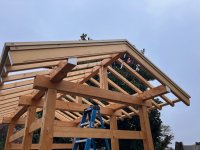
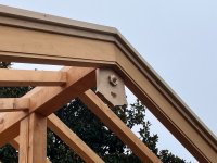
What you're calling a splice joint we would call a scarf*. The beauty of all the Japanese joints for this location is their resistance to twisting. The slot along the ridge beam is just perfect for concealing wiring.

...having a horizontal base to the housings for the rafters, and putting a birdsmouth on the underside of the rafters, would have made this an even better roof structurally.
/quote]
Yes, also called a scarf joint here.

On the birdsmouth: I will disagree that in this particular case a birdsmouth would be stronger. The rafters are only 65 mm tall. A birdsmouth would lessen that quite a bit at a critical position because the rafter ends support a wide eave (about 30 inches). That puts quite a bit of leverage on that eave/rafter joint. The eave beam/top plate is hefty enough to support being notched instead of having the small rafters notched. To prevent the rafters from sliding off the roof they are screwed down with 5 inch screws into the ridge and eave.
 
I meant everything staying as you've got it, with the rafters notched into the ridge beam, but a horizontal bottom to that notch/ housing rather than a sloped one and a corresponding flat on the underside of the rafter.......which you can even have housed into the ridge beam if you chose. This might have done away with the need for a fastening to prevent the rafter sliding downhill*. But ho hum......it's a trivial aside (maybe consider it for your next Japanese-style roof! :) ).

*Actually the predominant force on most lightweight roof coverings such as you propose is uplift due to wind, so nailing or strapping the rafters down would always be necessary.
 
Thanks, Mike. I see now.

And since you've all now seen the major parts of the frame here are two videos from frame raising day last July 29th. One is a frenetic time lapse of the whole affair. Four hours compressed to four minutes. That is me with the blue cap in the beginning whipping the crew into shape. We took a break about half way through so keep watching.

We assembled the frame on two beams set on cribbing and suspended over the threaded rods/stones. I wasn't sure exactly how we were going to lower the frame safely and had jacks and levers prepared. In the event, we decided there were enough of us to just pick the d**n thing up, remove cribbing, and set it back down. Done in 2 minutes.

https://www.youtube.com/watch?v=c7pXw2znRWw

The next is a collection of shorts in real time. This has sound and shows some of the assembly that was done off-camera in the time lapse.

https://www.youtube.com/watch?v=4qd50X1v9k0

I had a crew of twelve, which was about eight more than needed but when folks heard that I was having a Japanese timber frame raising it was hard to keep them away. Only one was a professional carpenter but all were enthusiastic amateur woodworkers and (importantly) all had a good sense of humor/humour.

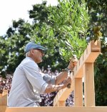
And me fixing the ceremonial evergreen bough to the ridge.

FB358F71-6551-45C1-9996-B1DB12DDF2A8_1_105_c.jpeg

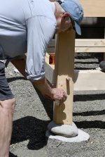
And another ceremony. When the main frame is finished there is another offering to the local spirits to ask for a strong building. Rice and salt are sprinkled on the ground, and bit of sake is poured directly onto the posts. Me doing the honors before handing off to the rest of the crew.

B08D8C96-9EA6-491C-8760-4D57E65FB026_1_105_c.jpeg
 
After the frame raising I put up the barge boards. I needed to do that before the rafters because the final rafter length needed to be 30 mm shorter than the length of the barges. The plan then was to set the barge boards, put up the rafters temporarily, snap a line, and take them down to cut to length.

That does seem unnecessarily complicated but there was a slight residual curve in the ridge beam that meant that a few of the rafter lengths needed to be adjusted to meet the eave evenly. In any case, I got it done.

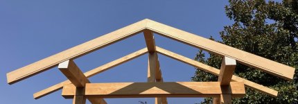
One barge board end up and starting to temporarily set the rafters. You can see I added a small decorative rebate to the bottom of the barge board. The eave beam ends I painted with linseed oil paint. White to keep away moisture and evil spirits.And yes, the sky is often that blue here in August I'm happy to report.
C418AF8E-BA7B-45D5-870C-FFE06851D34B_1_105_c.jpeg

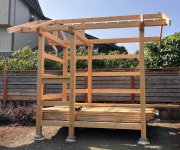
More of the site. I had a pile of boards lying around waiting to be milled into ceiling boards and roof decking. I was looking around the garden seeking a place to stack them when I thought, "Wait a minute...I have a shed!"
55816168-84F6-41CA-AAEE-19938E14B8B4_1_105_c.jpeg

I was also concerned that my construction would disturb my neighbour. We are friendly and I want to keep it that way. So I invited him to be part of the crew. Now he can hardly object since he helped build it!

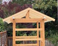
Rafters cut to length, fit and installed. Sharp eyes will notice the blue painter's tape used to keep the end grain paint contained.
9EF01D42-58A3-4465-B752-94EFB7A773CE_1_105_c.jpeg

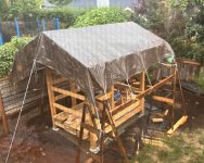
And then the rains came.

40E0205D-E3B7-43FB-8629-24B5D71CD356_1_105_c.jpeg

The view is through the screen on our window at our kitchen sink. One reason I wanted to build a nicer-than-needs-to-be shed is that the site dominates the view from here where we both look out often.

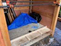
Before finishing the roof I decided to finish the floor so would have a stable base for ladders. Moving all of those ceiling and roof boards to sawhorses and under wraps. And then finish milling the floor joists.

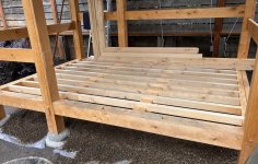
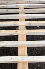
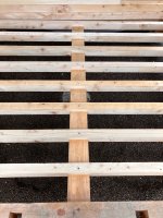
The Japanese carpentry book I am using for most of this suggests that the most common method used is to lay the joists on top of the sleepers and screw them down but, "for finer work" they should be cogged lap jointed." I can see why since lapping them prevents them from rolling over. Challenge accepted.

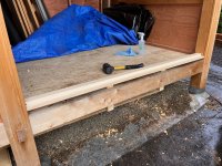
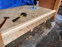
Here is the nearly finished view. The joists are the same dimensions as the rafters, 50 x 65 mm in section. That made milling all of them efficient. And noisy and boring.
B1C6091D-89F5-4E2B-8A31-DE063FE21F16_1_105_c.jpeg
D6022E11-E8FE-4339-BBDE-9D562BA54B34_1_105_c.jpeg

One other method I used to install the joists was to mill them slightly over width (50.5 mm rather than 50) and then use the kigoroshi ("wood killing) method to compress the fibers on the sides of the joists. After fitting the changes in humidity or a spritz of water swells the wood back to nearly original for a seamless fit.

https://covingtonandsons.com/2020/06/27 ... kigoroshi/

I had heard of this method but never used it. It works and is so much fun! After sweating the layout and carefully milling your wood and cutting to lines or half-lines and chiseling surfaces as flat as possible you get out your hammer and just beat on it.

Here is a short video of kigoroshi to fit one of my floor joists. I cut the video off before finishing the rest of the laps but you can get the idea. And I used the same method for fitting the rafters to their laps and mortices.

https://www.youtube.com/watch?v=GQllcq5Tct0

After all of that, I also screwed the joists down so they could not lift up later. Belts and braces (or belts and suspenders as we say over here).
9DED730A-FB2A-43A5-9FE9-9B3A3BED862C_1_105_c.jpeg


]
 
I'm curious about the two mortices in the threshold, Gary. What are they for?
 
Why, those are the for the shikii, of course! I was going to write about that later but since you brought it up I'll do it now.

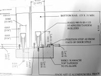
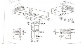
A shikii is a threshold with grooves or tracks for sliding doors. Also found as a cill for windows. Here is a schematic of one version. The diagram is from Len Brackett's book, Building the Japanese House Today

E4137362-287E-4D7F-81E7-424807C76F1A_1_105_c.jpeg

The shikii gets worn from traffic over it and is designed to be replaceable. The method for installing the shikii I'm taking from Shinzo Togashi's book on carpentry joinery. It involves a stub tenon on one end and a spline on the other that insert into the surrounding posts to keep the ends of the shikii from bowing up or twisting. To keep the middle from bowing up there is a yatoi hozo that drops into the mortice in the floor beam you noticed. I used two but one would probably have been enough. The shikii must remain flat or the doors could bind.

79FB260C-5AF6-43C9-A9C6-F86857450775_1_105_c.jpeg

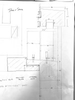
My version is actually a variation that divides the shikii into two parts. One fixed to the floor beam as described, and then a second stepped down member that carries the door tracks. That moves the door jamb outside the frame and provides a little extra weather protection to the frame.

Here is a sketch of a section through the threshold. The part that has the yatoi hozo is the L-shaped piece on the left.
951C7E0F-887B-4B60-8B12-59570D654FB0_1_201_a.jpeg

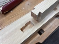
I just finished installing this part last week. Here what that looked like.
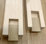
The mortice for the yatoi hozo.
03F1DBF5-9B3E-47B6-AE58-A72CF9B0AD1C_1_105_c.jpeg

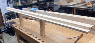
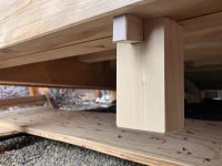
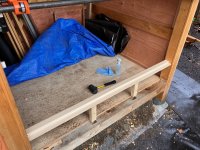
The shikii with yatoi hozo in place.You can also just make out the mortice for a spline on the near end. Rather than a stub tenon on the other end I opted to use a second spline.

CF4BDF0F-BC03-4E8A-B56A-D56F56A12DA4_1_105_c.jpeg

On installation the goal is to get a tight fit against the posts on either end. That required some careful layout and trimming of both ends since the yatoi hozo fix the position of shikii. The shikii should actually be a fraction of a mm long on both ends. On installation, spreader bars (I used reversible clamps/cramps) are used to press the posts apart just enough to let the shikii slip in.

BC7FA3E3-00D2-4A5B-BE51-76ABA291839E_1_105_c.jpeg

Shikii held by friction. Another quarter turn of the spreader let it drop. Then a few taps of the hammer to seat it.
5A4A934B-2C08-46F1-9F59-BE352F0E2DBD_1_105_c.jpeg

When fully down it is fixed in place by wedges through the arms of the yatoi hozo.
80FE2C94-CB65-49C5-B63D-73709DB50BDA_1_105_c.jpeg
E4CFDEB6-6720-41B8-B130-EB1AC6BE6B44_1_105_c.jpeg

I have the parts for the external jambs and door tracks made but not assembled. I'll come back to that later when it is finished.
 

Attachments

  • B2BEA6C7-5CD2-4B5B-B7A4-55A9F058D38F_1_105_c.jpeg
    B2BEA6C7-5CD2-4B5B-B7A4-55A9F058D38F_1_105_c.jpeg
    398.7 KB · Views: 881
Finally managed to view the videos. That is a sizeable labour force you have there for what must be quite a light frame.... :lol:

Interesting to see the sliding door structure - I've never seen the method broken down before.
 
Since we have gone on to the door and window assembly I thought I'd continue and show the upper parts. They have delightfully uncommon joinery as well.

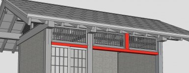
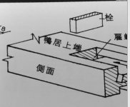
The upper counterpart to the shikii is called the kamoi. It is a combination door track, upper jamb, and header. The parts are highlighted here. The short vertical post connects the door kamoi to the eave beam to prevent the longer span of that kamoi from sagging.

13236FB3-104D-4BF4-9F63-90D9A900B17F_1_105_c.jpeg

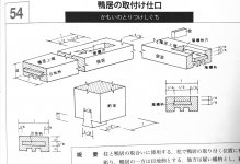
Like the shikii, the kamoi are intended to be replaceable when worn out by the doors or windows rubbing on them. They are always inserted after the building frame is assembled and fit tightly to the frame. The joinery is a bit different from the shikii. Typically there is a stub tenon on one end and in modern construction the other end is pocket screwed or nailed to the post. The joinery option is to use this dovetailed sliding tenon.

22BE6013-A9B2-4766-9964-BAE6BAF3A38A_1_201_a.jpeg

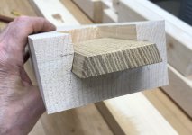
I wanted to push the use of joinery and I could see no reason not to use the sliding tenon on both ends. I thought that would simplify installation, especially of the door kamoi since I had also to insert the suspending post into the eave beam/top plate. Here is my version of the sliding tenon. The wood is black locust, Robinia pseudoacacia. Hard and rot resistant. I did the same for the window kamoi. The mortices in the posts for these were just over 15 mm deep.
77EC283B-6B49-478F-9EBD-CA08B2B849EA_1_105_c.jpeg
DCCBC051-8938-48AA-9D89-8D0B8213AB3D_1_201_a.jpeg

I'm using metal track for the shikii that will permit wheeled rollers for the doors and windows. The kamoi have grooves that will capture the tops of the doors and windows. To cut the grooves I used a portable Makita groover. I don't know whether these are sold where you are. They can't be sold commercially in the USA because they are deemed unsafe. Here we would probably use a router or maybe a dado blade in a table saw. It is not illegal to own one, however, so I bought one used from Japan. Being made for the Japanese market the motor is wired for 100 volts at 50 cycles/sec. USA standard is 120 volts and 60 cps. It works just fine on our higher voltage, though, and the plugs are the same so it can be used here unmodified. Used machines are inexpensive. Cutters are spendy but available with diligent searching.

Here is a video clip of me trying it out on some scrap. It is a joy to use. Heavy, stable, the ergonomics are great, not too noisy for what it does, leaves an impressively smooth cut. MUCH easier and faster than using a router for the same job. It will make grooves from I think 3 mm up to 42 mm wide. I have cutters for 9, 15, 21, and 36 mm. The downsides are there is no easy way to manage dust/chip collection and it throws chips a considerable distance away from the operator. I do not recommend using it inside your shop. And the cutter is not guarded when it is not in the work. Definitely requires paying attention.

https://www.youtube.com/watch?v=w3xcinki-YE

I had many more grooves to make in other places and this thing made what would have been drudgery actually kind of fun.

Here is the window kamoi after installation. AYou can see the post spreaders I used below it. I will say that I did later have to remove this kamoi for some adjustments. I put some temporary screws into it and levered it back out with a pry bar with no issues. After finishing the fit one drops a little block into the gap behind the tenon to keep it from working itself out.

E12EF741-5563-451A-96BF-B24B6F8B4401_1_105_c.jpeg

I cut the mortices in the posts to accept the sliding tenons after the frame was assembled. That took some careful measurements to make sure the mortices on both post were at the same level. And it was awkward laying/setting out and then chiseling out those mortices while standing on a saw horse. But it worked. I will say I was a little surprised. Lots could have gone wrong.
 

Attachments

  • E38C79A2-E7C3-4426-88F2-8EC471435E7C_1_105_c.jpeg
    E38C79A2-E7C3-4426-88F2-8EC471435E7C_1_105_c.jpeg
    282.2 KB · Views: 795
Black locust is, I think, better known as robinia here. I've never seen it sold by a timber merchant. That dovetailed loose tenon would need to be a perfect fit in both pieces of timber because there is no positive lock into position, although if it were loose, and the door head wobbled, you could easily tosh-screw to secure it.
 
Not related to Mike's post, but doesn't using screws rather defeat the object of this style of Japanese joinery, which is surely intended to allow a degree of movement? Aren't screws likely to exacerbate splitting risk?

I don't like using screws in oak framing (nearly all of which is loose pegged - by loose I mean not glued) because oak is very prone to seasonal movement whatever you do and because the tannins eat screws, even if coated.

The jointing methods you have used are intriguing and skilled. However, I'm not sure I would want to be cutting them in larger timbers, especially in dry hardwood.

What books would you recommend on Japanese carpetry? I already have the Azby Brown well known book that focuses on temple design and construction, and a couple from Toshoi Odate (that mainly relate to J tool use and history). Could have sworn I have one on general carpentry but can't find it after a reorganisation forced upon me at home.
 
We happen to have a Robinia in the garden. Parkland guys know it is "bastard" acacia for some reason. It flowers profusely and reminds me of a laburnum in that respect, except white not yellow. They sucker and I find the sap very irritating to the skin. They've got a couple at Sissinghurst as well in the outlier area and Troy the main man there says they are dying out in the UK due to some disease. Mike at Timberline very occasionally has some smallish Robinia in stock, though it's quite a while since I've seen any there.
 
Just watched your video of the groover. Never seen one in the UK and don't remember seeing one in Japan either. They don't strike me as any more dangerous than a wall chaser or angle grinder.
 
AJB Temple":319bef3y said:
What books would you recommend on Japanese carpetry? I already have the Azby Brown well known book that focuses on temple design and construction, and a couple from Toshoi Odate (that mainly relate to J tool use and history). Could have sworn I have one on general carpentry but can't find it after a reorganisation forced upon me at home.

I've been looking for a copy of Hideo Sato's book "The Complete Japanese Joinery" for a couple of years now, but it never seems to be available anywhere at a sensible price. Of course I can't comment on whether it's any good as I haven't got it!

The Toshio Odate books I've got are very good.

I would also be interested in Gary's recommendations.
 
Mike G":1sfptkxw said:
Black locust is, I think, better known as robinia here. I've never seen it sold by a timber merchant. That dovetailed loose tenon would need to be a perfect fit in both pieces of timber because there is no positive lock into position, although if it were loose, and the door head wobbled, you could easily tosh-screw to secure it.

Robinia is used here often for fence posts and outdoor decks because it is so rot resistant.

There is an old New England joke about how to build a fence that lasts. "Dig your hole, put a nice granite rock in the bottom, set your locust post on that and fill in the hole. Then leave a note for your great grandchildren reminding them to come back in 100 years to replace the rock."

Mike there is a positive lock for the loose tenon. I haven't added it to mine yet but you can see it the Japanese diagram. A small filler block drops in behind the tenon.
Screenshot 2024-02-02 at 7.02.50 AM.jpg

Books on Japanese joinery and construction. I have also looked for the Sato book but like you Al I have found it is difficult or too expensive to buy. There is an abbreviated version of it, though. A few chapters of Sato's book were combined with a few chapters of Nakahara's book and re-published as The Complete Japanese Joinery. It has some typos and problems with repetition and continuity. Probably a little out of date but is still a go-to book. It also includes Western building practices as modified for Japanese structures.
517CD8AD-DDED-40C6-968E-7C7921AF76EA.JPG
For traditional, pre WWII Japanese residential architecture the books by Heinrich/Heino Engel are good. The longer original one is probably less useful since it is stuffed with his impenetrable musings on Japanese culture and "the meaning of it all." (It includes a publisher's note saying basically, "Don't blame us! This book really needed a good editor but Engel insisted we publish every word as written or not at all. Good luck.") A better value is Measure and Construction of the Japanese House, same author, but only the chapter of the original on construction methods with his excellent architectural drawings. I like him because he is critical of those aspects of Japanese building that aren't soundly engineered.

D10AFE5A-0B41-4746-A0BD-BFFE100ADE75_1_201_a.jpeg

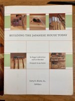
Rao and Brackett's book Building the Japanese House Today is a classic. It uses the construction of a single high end residence in California to illustrate how Brackett's company (East Wind/Higashi Kaze) adapts Japanese design for Western living and California's strict building codes. Although mostly a coffee table book with sumptuous photography, it also includes architectural drawings that detail roofs/rooves, doors, walls, and the Japanese method of "kiwari" or how to proportion the frame parts relative to the size of the posts.
https://www.eastwindinc.com/
0CA62FBC-5846-4150-947F-79E56CAB2AED.JPG

There are many picture books on Japanese joinery but few show how to lay out/set out the joints. For that I like Shinzo Togashi's book. I have shown a few of his diagrams already. There is very little text but most of us can't read it anyway. I have tried various ways to translate his notes and figure captions but I find that there the many specialized woodworking terms don't machine translate into anything sensible in English. But his diagrams are superb and I find readily understandable. Photo of the cover and the ISBN number.

6A09133A-0B86-447F-82B9-ADA4FA78DD92_4_5005_c.jpeg
08A81DC5-0A7C-4C15-B499-52DA5CC8C79B_4_5005_c.jpeg

And if you are up for it, Togashi has other books showing the joinery layout and construction for temples and gates. I don't have either of those (they are expensive) but would love to have them.

Saving the best for last, I highly, highly recommend any and all of the monographs by the late Chris Hall. A Canadian who trained in Japan, California, and Canada before establishing his own building company in Massachusetts. He wrote extensively for his blog, The Carpentry Way and also wrote his monographs on various aspects of Japanese carpentry and joinery. Sadly, he died a few years ago but his widow maintains his web site and still sells his monographs downloadable as pdfs. His 200 page monograph on splicing joints will amaze. He has another that is an extended description and analysis of a single joint. Excellent drawings and detailed step by step cut sequences for many of the joints.

https://thecarpentryway.blog/buy-pdfs-o ... materials/

And do take the time to explore his blog and build threads. There is no other resource in English like it.

(disclaimer: I have a recent guest post there showing a Ming era table I made).
 
wow this is quite the project, I'm very impressed with the joinery! it's also beautiful to look at, did you burn the underside of the timbers that were scribed to the stones? I only ask because I saw that dude mr chikadee do it and thought it might help prevent rot and decay.
 
thetyreman":2d0ym9zx said:
did you burn the underside of the timbers that were scribed to the stones? I only ask because I saw that dude mr chikadee do it and thought it might help prevent rot and decay.

I considered it but I after reading about it I decided that I didn't think I would like how it looked, and my understanding is that the technique isn't that effective on thick timbers since it only works on the surface. If the untreated wood below the char gets wet and stays wet, the post will rot anyway. Also, Port Orford cedar is naturally rot resistant. Putting a torch to your shed makes a great video, though!

I did seal the end grain of the posts with a linseed oil/tung oil/pine resin/beeswax mix to resist water wicking up from the stone. The two short internal posts under the sleepers also have a plastic capillary break under them.
 
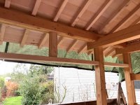
Let's go up on the roof.

The design I am using is a plain vanilla version of a common Japanese residential roof that exposes the rafters as part of a finished ceiling. Mine is a little nicer than a simple shed roof but not insulated as a residential roof would be.

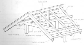
Here is a view that shows the elements above the rafters.
DF23D176-F732-49D8-8D74-3B721D9FAE93_1_201_a.jpeg

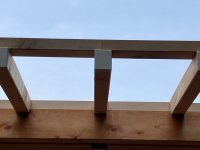
From the rafters up what you are looking at is a joined perimeter frame that surrounds a layer of lapped ceiling boards. On top of the perimeter frame/ceiling boards is another perimeter frame and furring strips aligned with the rafters, screwed to them to keep the ceiling boards flat, and support the plank roof decking that is being installed.

The lower perimeter frame is called the hirogomai, sometimes spelled hirokomai, 広小舞. The upper frame is called a yoda facia. Here is another diagram from Sato and Nakahara's book similar to what I'm doing:

42165D3C-F9FD-41FD-B424-7244B291961B_1_105_c.jpeg

(Tip for the curious: an excellent source for translating Japanese architectural terms to English, and the reverse, is JAANUS. https://www.aisf.or.jp/%7Ejaanus/ What I like to do is input a word I read somewhere, like "komai" or "shikii" or "rafter" and see what is there. Then cut and paste the Japanese characters into an internet search to reach the Japanese text or image or video results). Being able to search the internet with Japanese characters is truly helpful).

On my simple roof the lower frame, the hirogomai, as I see it does three things. Most important is that it supports the rafter ends to keep them aligned and keep them from sagging. Second is that it covers, hides, and protects the end grain ends of the ceiling boards. Third is that it overlaps the barge board to provide a drip edge and shadow line.

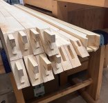
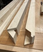
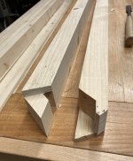
The hirogomai frame is always mitred to cover the end grain. In less expensive work it is simply cut and screwed down. In better work it is joined with any number of methods. I chose a relatively simple through and wedged haunched tenon version. I hope you can figure out the joinery from these pictures.

F859C280-3D31-498D-82AC-1EBF847C39A2_1_105_c.jpeg

8E4298AA-0285-488B-B005-FC98B926A941_1_105_c.jpeg

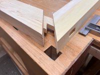
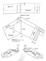
That is straightforward M&T joinery. There is additional fun joinery at the ridge where the hirogomai frames on the two gable faces meet at an angle at the ridge . Here is Togashi-san's drawing:
E8E11E8A-D8A2-4D77-9AC2-55237625A666_1_201_a.jpeg

And my attempt.Getting the angles right, and the distances from the mitered corners, was a challenge. I mostly succeeded but not entirely. I got the ridge joinery right but the frame on one gable side ended up about 10 mm longer down to the eave than the other. Not sure how that happened but I didn't have the wood or the desire to do over. Don't tell anyone. No one beside me and a real Japanese carpenter will notice.

928A390E-81F2-4AAD-BD4C-81E6A0F7D5C4_1_105_c.jpeg

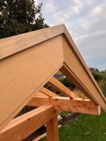
And what the hirogomai looked like when it was installed on top of the barge board. The trick is to get the mitres of the hirogomai aligned exactly with the barge board mitres and an even overlap. This view looks good. Overall I think I got about 90% there.

AB4733D6-090F-4CE4-A5F0-82ABAA37268B_1_105_c.jpeg
 

Attachments

  • 928A390E-81F2-4AAD-BD4C-81E6A0F7D5C4_1_105_c.jpeg
    928A390E-81F2-4AAD-BD4C-81E6A0F7D5C4_1_105_c.jpeg
    216 KB · Views: 1,098
If I'm reading this right, you've got an unventilated void either side of the firring pieces. That's fine in an unheated building, but it is also a potential insect haven. I'm sure you went around carefully checking for any tiny hole or gap they might exploit, because taking the roof to pieces to remove a wasp or bee nest doesn't bear thinking about.

Anyway, this is looking great. The joinery forces much larger timber sections than you'd need if just nailing or screwing pieces together, and that's part of what drives the aesthetic. How far off "real time" are we, or have you finished already?
 
Mike, thanks for the tip about bee-proofing. I had not considered that and will now add it to my list of things to worry about! And address....

We are almost up to current times. I finished decking the roof and applied the underlayment/weather barrier over the decking in early December. It started raining regularly then so I could not get the metal panels installed and the whole thing is under tarps again until we get some dry weather.

I did add a few other parts. Eave blocking between the rafters. Those fit into shallow grooves routed in the rafter sides.

FD1E9890-3653-46A0-8FB2-EE9D14027FF6_1_105_c.jpeg

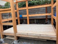
Plywood subfloor. I have since also added plywood sheathing to the walls but that is truly ugly so I won't bother showing it. The sheathing will later be hidden by plaster.

3C927E7F-F17B-47B1-90BB-C523068E4603_1_105_c.jpeg

Forgot to show the upper perimeter frame of the roof. It overlaps the lower to create a second drip edge and shadow line. If you look on the left side you can see that the lower perimeter frame is held back from the rafter and barge board ends while the upper frame extends beyond both to protect the rafter ends.

EF0E287C-C74F-451F-B07E-DB2C42ADE175_1_105_c.jpeg

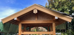
And strictly for decoration I added the gable pendant. In Japanese called a gegyo 懸魚. The name literally means "hanging fish," although the origin of the name is obscure. Sources guess that early versions may have actually been shaped like a fish, that done as a means to summon water to ward off fire. In any case, there are several classic styles for these pendants. Mine is a simpler one that uses a common 6-leaf motif. The small plug in the center represents a bung, meaning to show there is metaphorical water stored behind, again to ward off fire. Or so they say.

36C21236-1EA0-42C9-B498-E8CBA3C9BC44_1_105_c.jpeg

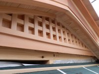
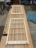
I have also added latticed sash to fill in the gable ends. That was a fun chore. The lattices are lapped as well as mortice and tenoned into their frames. This is a fairly common way to finish the gable end walls but usually they are backed by solid wood to seal off the attic space. In my case I'm leaving them open for ventilation, although I will back them by insect screen. Have to keep those bees out, you know!

A9572CAA-4278-42BE-9F8E-B6BA1242E31C_1_201_a.jpeg

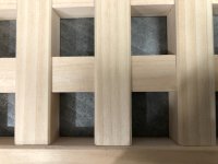
Detail of the lattice.

lattice - 1.jpeg


One of my references on gable end design (barge board shape and edge treatments, amount and number of overlaps and set backs, etc) said the details vary from place to place and carpenter to carpenter, but advised that the overall look to the gable end should be "serene." Does this look serene enough to you?

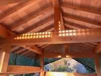
I also forgot to show the ceiling boards. These are lapped and all the visible surface is hand planed. In fact, all of the visible surfaces of the posts, beams, and ceiling boards are hand planed. The planing took a while but it was pleasant work. POC is just lovely to work with hand planes. The gable ends face east/west. When the afternoon sun gets low enough it produces this delightful pattern on the beams inside.

413473A1-7394-4AB6-ABDA-1297140EC76B_1_105_c.jpeg

Now we are up to date. I'm in the shop these days working on the windows and doors. I'll show that work when it gets far enough along.
 
Thank you very much for the book recommendations and the blog link. I've ordered the cheaper Hengel book (though I have a feeling I already have it somewhere) to start with. I'd like the Bracket & Rao book very much, but its £100 shipped and I can't justify that for a casual browse.

Your roof joinery is superb. Very impressed with that and also the super neat screen work.

I doubt you will have a problem with bees, as wild honey bees at least like a fair amount of space for comb building and the scouts will generally reject spaces that don't have capacity for say 60,000 workers. we collect a few swarms each year locally for re-housing and they can be teased out generally. Wasps and hornets are a different matter and we find them a seasonal nuisance in our barn roof. They will build even quite small nests, though only the queens overwinter usually.
 
That looks great Gary. I really like the lattice in the gables.

Don't forget, Adrian, that Gary lives in the US. They have a whole lot of insects we don't have. Our bees and wasps can be a nuisance, but they've got plenty more to choose from over there.
 
Most impressed Gary, love the patterns of light and yes most serene, I hadn’t imagined they would be as thick, depthwise though, but they do look right and that’s often all that matters.
One thing I had never thought about with Japanese buildings is that the inside is plastered! I just assumed they were wood or screens.
All the plasterers that I have ever come across are far to messy to let loose in your lovely little- you can’t call it a shed!
Ian
 
Cabinetman":2zpec6tn said:
I hadn’t imagined they would be as thick, depthwise though, but they do look right and that’s often all that matters.
One thing I had never thought about with Japanese buildings is that the inside is plastered!

Ian

Yes the lattice is robust. It got the original idea from these pictures, one of a Japanese house built in California and the other in Japan. Note the subtle feature of the verticals proud of the horizontals, adding a layer of depth and shadow line. I love that look.

901C13AB-9123-4CA9-BD01-F25627F8336D.png
2B5977CE-3B5C-4FEF-89AF-5C47029100C4.jpeg

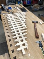
They were not easy to make. The sloped upper rail greatly increased the difficulty and resulted in some fragile tapered bits of lattice. Some I could not save but since the gables are 3 meters in the air no one will notice. It took me a few tries and some jiggery to get all the sloped shoulders on the vertical tenons to line up precisely along the upper frame angle. Here's a look behind the curtain:

369632F5-6901-457E-A77B-752298FC27F1_1_105_c.jpeg

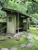
Japanese plastering was new to me, too. But they have a long tradition. In fact, the traditional Japanese wall is a mud wall, rather like cob, built around bamboo lath and finished with clay plaster. Sometimes lime plaster/render outside. It is a beautiful complement to all the exposed wood. Here is a simple garden structure I photographed at the Japanese Garden in Portland, Oregon. My shed will eventually have a similar look once it ages, I hope.

876DAC39-43E9-494A-BC39-AF69C85B6A94_1_105_c.jpeg

Japanese plaster is a fascinating rabbit hole to go down. Here is an introduction.

https://japaneseplastering.com/fundamen ... e-finishes
 
A few days of clear weather allowed me (with neighbour's help) to get the roof flashing on.

15762B65-1E24-4424-8FD3-AFBFD61C1CCE_1_105_c.jpeg

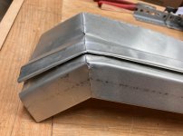
That took a little head scratching and texts with the manufacturer to work out the details. They sell mostly to professional roofers and maybe not so used to hand-holding with novices and DIY types like me. One complication was how to cut and bend the rake flashing where it meets the ridge. I mocked up what I thought would work in cardboard and sent a picture to their master roofer for his thoughts. He replied that he had never tried to bend the stainless steel flashing I ordered in that way, but if I thought I could do it, then it would work well. This from a German-trained spenglermeister!.

Here was my practice version in the tin coated stainless steel I'm using. I showed that to the spenglermeister and he replied, "It looks good." So there! The two for-real versions came out a little better.

9636791F-6568-4940-A27D-3C9C4B063334.jpeg

I hope to start installing the metal panels tomorrow.
 
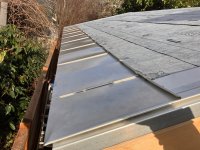
One row of metal panels installed. Most of the time was spent on snapping layout lines and fussing with the fit of the first panel at the corner. The other four panels interlock with the first and with each other, and the drip edge and are fastened on the upslope side with clips. It should go faster as we gain experience.

B94A4770-9F4C-46ED-973B-A357D80514CC_1_105_c.jpeg
 
That's a curious choice of material, for me. What drove you to put a modern and very western material on this building? Or is it just a holding strategy whilst you hand fabricate a heap of shingles...
 
It is curious, isn't it? I gave the roof a lot of thought.

My design priorities were to have a roof that was durable, low maintenance, light weight, fire resistant, and doable as a DIY job.

My first thought was to use ceramic or concrete tile. Our house has gray concrete tile and I like the look and longevity and fire resistance. But it is very heavy and I would have had to beef up the roof structure quite a bit. Concrete tile is also not a great DIY solution for a 71 year old man. I decided against wood bark or wood shingles, which are a moss magnet in my climate, and a fire hazard, and not particularly long lasting here. Copper shingles are sometimes used and look great but those are outrageously expensive and attractive to thieves. Slate is sometimes used but in the USA slate mostly comes from the east and shipping costs are prohibitive. I don't like the look of asphalt or rubberized composite shingles

These metal panels are tin coated stainless steel, extremely durable (100 year), light weight, fire resistant, and low maintenance. They should look better with age rather than worse.

I admit I am not crazy about the pattern they make and asked about getting a custom shape but they said they couldn't do that. After I bought these the company introduced a "Prairie Style" version with stronger horizontal lines which would have been perfect. But too late for me.
 
Back
Top