
-
Hi all and welcome to TheWoodHaven2 brought into the 21st Century, kicking and screaming! We all have Alasdair to thank for the vast bulk of the heavy lifting to get us here, no more so than me because he's taken away a huge burden of responsibility from my shoulders and brought us to this new shiny home, with all your previous content (hopefully) still intact! Please peruse and feed back. There is still plenty to do, like changing the colour scheme, adding the banner graphic, tweaking the odd setting here and there so I have added a new thread in the 'Technical Issues, Bugs and Feature Requests' forum for you to add any issues you find, any missing settings or just anything you'd like to see added/removed from the feature set that Xenforo offers. We will get to everything over the coming weeks so please be patient, but add anything at all to the thread I mention above and we promise to get to them over the next few days/weeks/months. In the meantime, please enjoy!
You are using an out of date browser. It may not display this or other websites correctly.
You should upgrade or use an alternative browser.
You should upgrade or use an alternative browser.
A Japanese style garden shed
- Thread starter GaryR
- Start date

Cabinetman
Sequoia
- Joined
- Oct 11, 2020
- Messages
- 5,786
- Reaction score
- 1,443
- Location
- Lincolnshire Wolds + Massachusetts
- Name
- Ian
Fascinating, it all makes sense and is very neat when together I suppose but to my eyes looks a bit flimsy, not that I’m suggesting they don’t know what they’re doing after thousands of earthquakes and broken joints to learn from!
Just had a quick look at Oregon, gosh it’s beautiful! But as it says seven diverse regions, ocean, mountains, valleys, high desert, cities, small towns, and almost everything in between Being nr7 haha. What’s it like around you Gary?
Just had a quick look at Oregon, gosh it’s beautiful! But as it says seven diverse regions, ocean, mountains, valleys, high desert, cities, small towns, and almost everything in between Being nr7 haha. What’s it like around you Gary?
GaryR
Nordic Pine
Cabinetman":pz6jjq94 said:Fascinating, it all makes sense and is very neat when together I suppose but to my eyes looks a bit flimsy, not that I’m suggesting they don’t know what they’re doing after thousands of earthquakes and broken joints to learn from!
No, no, you are exactly right. It is a clever design for sure, but it does remove a potentially dangerous amount of wood from that post. In context of a whole building with other members acting together it is probably sufficient because as you say, it has been in use for a long time. However, I understand that in Japan these days if one wants to use this joinery in new construction it must be reinforced with metal strapping.

Wow.
Assuming that you started out learning about ordinary western mortice & tenons etc, how much longer does it take to do that sort of fancy joint? Does it soon become second nature or do you need to keep referring to diagrams or a model?
Assuming that you started out learning about ordinary western mortice & tenons etc, how much longer does it take to do that sort of fancy joint? Does it soon become second nature or do you need to keep referring to diagrams or a model?
Cabinetman
Sequoia
- Joined
- Oct 11, 2020
- Messages
- 5,786
- Reaction score
- 1,443
- Location
- Lincolnshire Wolds + Massachusetts
- Name
- Ian
Killjoys! I saw a video of a Chinese temple being given the shakes in an experiment, absolutely fascinating the way it stood up to it.
Edited my previous comment after you read it, sorry.
Edited my previous comment after you read it, sorry.

Mike G
Petrified Pine
GaryR":1ys9jugr said:.....Aesthetically, the angled feature in the simpler joint exposes the joinery. That can be appealing. But in both western and Japanese furniture and building, exposed joinery is generally viewed as less refined than hidden joinery......
I live and work in the world of mediaeval low to mid-status timber-framed buildings, where exposed joinery was carved and/or moulded if refinement was sought. The joints themselves ranged from relatively crude to very sophisticated, and there was no attempt to sugar-coat them until you got to high status buildings such as manors, cathedrals, palaces, and so on.
GaryR
Nordic Pine
AndyT":18ywz1fr said:Wow.
Assuming that you started out learning about ordinary western mortice & tenons etc, how much longer does it take to do that sort of fancy joint? Does it soon become second nature or do you need to keep referring to diagrams or a model?
Well, it is an interesting thing. Yes, I had 30 years or so of off and on amateur furniture making behind me before I started down this path. As I mentioned above, these more complex joints are all about getting the layout correct. And I do refer to diagrams often. Sketchup helps with 3D visualization. After that, as a friend said, "it's just woodworking." Saw to a line, chisel waste, pare or plane surfaces flat. Be willing to make a few mistakes and start over. If it is a new joint I've not done before, like the one above, I'll practice on scraps first.
I didn't start doing Japanese style joinery until about five years ago when I retired. An old dog learning new tricks.
GaryR
Nordic Pine
Mike G":wlpbcyc9 said:I live and work in the world of mediaeval low to mid-status timber-framed buildings, where exposed joinery was carved and/or moulded if refinement was sought. The joints themselves ranged from relatively crude to very sophisticated, and there was no attempt to sugar-coat them until you got to high status buildings such as manors, cathedrals, palaces, and so on.
Yes that seems to be a universal: how it looks at the end depends on how much you are willing and able to pay!
I don't know as much about the English tradition apart from what I have read in a couple of books. Is it true that there used to be a much wider range of joinery choices used a few centuries ago than in use today?
GaryR
Nordic Pine
Cabinetman":t5e3sbkp said:Just had a quick look at Oregon, gosh it’s beautiful! But as it says seven diverse regions, ocean, mountains, valleys, high desert, cities, small towns, and almost everything in between Being nr7 haha. What’s it like around you Gary?
I live in Corvallis, a university town (Oregon State University) in the center of the Willamette Valley Population about 60,000. It is indeed beautiful here. I am about an hour's drive across the Oregon coast range from the Pacific ocean and two hours from the Cascade mountains. Most of the local industry is forestry/lumbering and agriculture. The Willamette valley grows just about every kind of vegetable. In the past 30 years the area has become a major wine grape region. Also hops. And filbert/hazelnut groves. And the grass seed capital of the world!
Mike G
Petrified Pine
GaryR":2o826597 said:.....Yes that seems to be a universal: how it looks at the end depends on how much you are willing and able to pay!
Very true. My part of the country is known for "close stud" timber framing (as opposed to the western 2/3rds of the country, where an intermediate horizontal created half-storey squares in the plasterwork.....Anne Hathaway's Cottage in Stratford is a classic example). Over here, you displayed your wealth by the number and size of your chimneys (later buildings only), by the amount of carving, and particularly, by the close spacing of your studs. The more timber, the richer you were. Look up Paycockes in Coggeshall for an example near me of a rich merchant displaying his wealth to the road-users with close timbers and carving (and indeed, through a broad facade).
I don't know as much about the English tradition apart from what I have read in a couple of books. Is it true that there used to be a much wider range of joinery choices used a few centuries ago than in use today?
I don't think so. Certainly not in my practice, where I have ready access to skilled joiners and framers quite capable of constructing any joint that I draw (I'm an architect). Jowls are typically avoided because of the sheer wastage of timber involved, but if they're called for, then even they are used, and I've even specified the classic jowled junction between a storey post, a wall plate, and a tie beam. That joint is just about the defining joint of English mediaeval timber framing, and so long as I can draw it (or any other), then there are people who can build it.
Cabinetman
Sequoia
- Joined
- Oct 11, 2020
- Messages
- 5,786
- Reaction score
- 1,443
- Location
- Lincolnshire Wolds + Massachusetts
- Name
- Ian
I have only one thing to say, COR!
No, it really does sound wonderful.
No, it really does sound wonderful.
GaryR
Nordic Pine
Mike G":3i38h0p5 said:in my practice, where I have ready access to skilled joiners and framers quite capable of constructing any joint that I draw (I'm an architect). Jowls are typically avoided because of the sheer wastage of timber involved, but if they're called for, then even they are used, and I've even specified the classic jowled junction between a storey post, a wall plate, and a tie beam. That joint is just about the defining joint of English mediaeval timber framing, and so long as I can draw it (or any other), then there are people who can build it.
That is wonderful! And inspiring!
GaryR
Nordic Pine
Before I go on with the joinery I should say where the project stands today. I finished the frame joinery last June. The frame raising was at the end of July. Video link to come later. August/September I did the floor joists and subfloor. October/November was the roof minus the cladding which will be terne metal panels. December was exterior sheathing infilled between the posts. Then a tarp over over the roof to endure the winter rains while I moved indoors. I've finished the door and window jambs and have started on the windows. More pictures to come.
To finish the floor: I showed the perimeter beams to posts joinery. There are also two sleepers. One is part of the three way joint you have seen. The other is joined at both ends with a double tenon, later pegged. Both of the sleepers are also fitted for cogged lap joints for the floor joists. The sleepers span a little less than 2 meters. Designing all of this so that the subfloor came to the right level was a challenge for me as a first-timer. One problem was realizing that the sleepers had to end up 30 mm below the perimeter beam surface. That required modifying the carpentry joinery book drawings, which was scary. I was a little worried about the load strength of that double tenon joint since it ended up so low on the perimeter beam so I later added an intermediate pier and post below both sleepers. All good now I think. Fingers crossed. Knock wood?
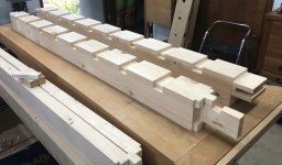
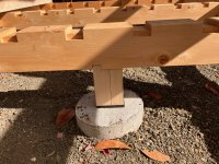
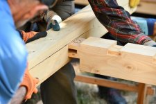
And a pic of the joint being assembled during the frame raising.
To finish the floor: I showed the perimeter beams to posts joinery. There are also two sleepers. One is part of the three way joint you have seen. The other is joined at both ends with a double tenon, later pegged. Both of the sleepers are also fitted for cogged lap joints for the floor joists. The sleepers span a little less than 2 meters. Designing all of this so that the subfloor came to the right level was a challenge for me as a first-timer. One problem was realizing that the sleepers had to end up 30 mm below the perimeter beam surface. That required modifying the carpentry joinery book drawings, which was scary. I was a little worried about the load strength of that double tenon joint since it ended up so low on the perimeter beam so I later added an intermediate pier and post below both sleepers. All good now I think. Fingers crossed. Knock wood?
And a pic of the joint being assembled during the frame raising.

AJB Temple
Sequoia
- Joined
- Apr 15, 2019
- Messages
- 7,832
- Reaction score
- 1,299
I admire your tenacity and willingness to insist on an authentic outcome.
When finished it will possibly be the world's most complex shed, and in terms of labour hours possibly the most expensive too. It really needs to become a shrine to outstanding joinery and a local visitor attraction. Your wife is very tolerant. Possibly a saint. Mine has started making remarks about me getting projects finished!
When finished it will possibly be the world's most complex shed, and in terms of labour hours possibly the most expensive too. It really needs to become a shrine to outstanding joinery and a local visitor attraction. Your wife is very tolerant. Possibly a saint. Mine has started making remarks about me getting projects finished!
Mike G
Petrified Pine
GaryR":1t0uc1yf said:.... More pictures to come....
Excellent. It would be nice to see some photos of work in progress on the joints. I'm curious as to how much hand-tool work you are employing.

Lons
Old Oak
AndyT":olk6054l said:I'll never need to build anything like this but I am enjoying the really interesting write up. Also the glimpses of the inside of your workshop...
Me too, very interesting. I wouldn't have the patience to use stones though can appreciate the reasons so would have just set the posts on rounded concrete.
Looking at the length of time needed for the project my wife would have forgotten what I was doing after just a couple of months, in fact it's a ploy I use regularly. :lol: If she queries nything I just say " I explained that ages ago and she walks away shaking her head.
GaryR
Nordic Pine
Mike G":21d2yryv said:GaryR":21d2yryv said:.... More pictures to come....
Excellent. It would be nice to see some photos of work in progress on the joints. I'm curious as to how much hand-tool work you are employing.
You may regret encouraging me. I have a lot of pictures.
Here are a few process pictures for the joints I've shown so far.
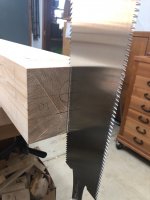
Tenons for the floor beam to post connection start with saw cuts. For these I used either a 270 or 250 mm ryouba saw. For the shoulder cuts that are finished surfaces I also clamped a saw guide to the work.
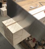
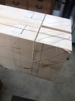
Rip cuts on the ends of the long beams I usually did with the saw held vertically or near vertically.
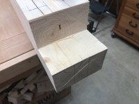
I used simple block milled precisely square to check for flatness and 90 degrees.
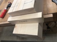
Two more rip cuts define the tenon shoulders, then a cross cut using a guide block.
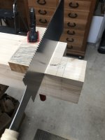
Then the other cheek and a little clean up with a chisel.
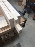
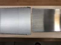
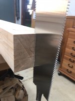
Then cross cuts for the stub tenons shoulders. This will be finished surface and not a deep cut so I switched to the finer 250 mm saw. You can see the difference in tooth size. It leaves a perfect kerf.
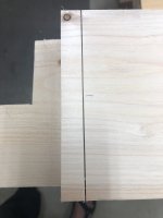
A couple more rip cuts remove the waste.
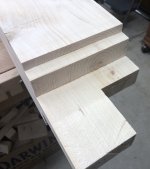
Re-establish the layout lines for the stub tenons, and chisel out the waste between them.
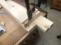
Nearly done.
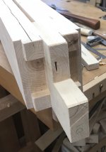
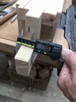
Check for fit. The target was 30 mm. I also used a go/no go template that slips over the tenon.
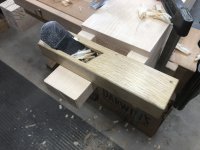
To clean up I mostly used a Japanese skewed rebate plane.

Attachments
Mike G
Petrified Pine
GaryR":9slv2u39 said:.......You may regret encouraging me. I have a lot of pictures.........
I believe I've posted over 6000 here. Good luck!
GaryR
Nordic Pine
AJB Temple":eezhrxja said:When finished it will possibly be the world's most complex shed, and in terms of labour hours possibly the most expensive too. It really needs to become a shrine to outstanding joinery and a local visitor attraction. Your wife is very tolerant. Possibly a saint. Mine has started making remarks about me getting projects finished!
Yes, I proudly tell folks who drop by to see my progress that my goal is "to build the least amount of shed for the greatest amount of effort!"
Dear wife is very patient. At least she knows where I am at all times, because I'm always working on the shed.
GaryR
Nordic Pine
For the post mortices I started with router templates setting the router to the 15 mm depth of the stub tenons. The router established the vertical walls for the rest of the mortice. The mortices for the half dovetailed nuki tenons were 30 mm x 135 mm x 90 mm deep. I removed most of the waste for those with an auger. I cleaned up the mortice walls with a framing chisel and a couple of Japanese slicks. Those are serious tools, believe me.
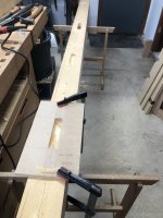
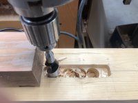
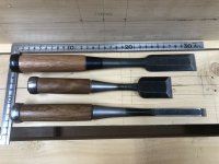
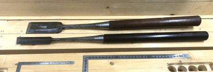
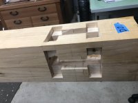
This one was a little rough. There were some interior knots that did not want to cooperate.
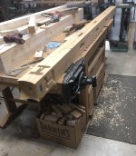
Of course having a decent bench dog is always useful.
This one was a little rough. There were some interior knots that did not want to cooperate.
Of course having a decent bench dog is always useful.
Mike G
Petrified Pine
That second last photo really highlights how much material is removed from the post.
Nice to see your photos of the work on the joints, too. Although I too use hand tools as much as I can, I also made a router template for the mortices in my sunroom, and it's amazing how much time that saves in setting out:


Nice to see your photos of the work on the joints, too. Although I too use hand tools as much as I can, I also made a router template for the mortices in my sunroom, and it's amazing how much time that saves in setting out:
AJB Temple
Sequoia
- Joined
- Apr 15, 2019
- Messages
- 7,832
- Reaction score
- 1,299
Excellent bench dog.
Mike G
Petrified Pine
AJB Temple":1po55fx0 said:Excellent bench dog.
They make a bit of noise when you bash them into the dog hole with a hammer, that's all.
GaryR
Nordic Pine
The orioki framing between the post, tie beam, and eave beam. It is the scheme on the right: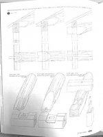
And my version. The stepped post tenons are straightforward saw work. For scale the smaller square tenon on top is 30 x 30 mm. Checking for fit with a template.
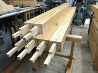
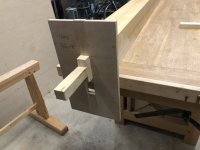
The stepped tenon inserts into a cogged lap joint between the tie beam and eave beam. I did the cogged laps with a combination of hand saw and chisels. I finished up later by decking the flats with a router.
These are the tie beams.
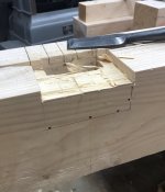
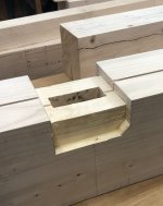
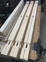
Here is test fitting one eave beam lap to its tie beam match. The slanted notch is for a rafter.
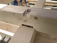
And my version. The stepped post tenons are straightforward saw work. For scale the smaller square tenon on top is 30 x 30 mm. Checking for fit with a template.
The stepped tenon inserts into a cogged lap joint between the tie beam and eave beam. I did the cogged laps with a combination of hand saw and chisels. I finished up later by decking the flats with a router.
These are the tie beams.
Here is test fitting one eave beam lap to its tie beam match. The slanted notch is for a rafter.
Cabinetman
Sequoia
- Joined
- Oct 11, 2020
- Messages
- 5,786
- Reaction score
- 1,443
- Location
- Lincolnshire Wolds + Massachusetts
- Name
- Ian
This is so very complex compared to a timber building from everywhere else, was it just the Earthquakes that necessitated it? Or is there just a bit of the Japanese psyche making things difficult deliberately?
What a lovely puppy!
What a lovely puppy!
GaryR
Nordic Pine
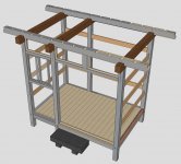
Eave beams, ridge beam, and barge boards have my favorite joinery of the project and trickiest to get right. Here are the eave beams and how they relate to the tie beams and the rest of the frame.
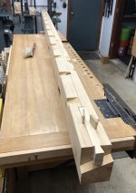
These beams at 13 ft were too long to take to my shop machines for flattening so I did that with a Makita portable planer and hand planes. Here is one of the eave beams. The slots for the rafters I did with hand saw and chisels. The sloped ledge on the end is to support the barge board on the gable end. (I assume that barge board is the same term in England?)
That loose tenon with the dovetailed end is called a yatoi hozo or yatoi sen. I don't think there is anything like it in Western framing but it and multiple variations are common in Japanese woodworking where it is used for splice joints and some right angle connections as used here. I think It is worth a close look.
The yatoi hoze used here joins the barge board to the eave beam without metal fasteners. I used a slightly different version for the ridge beam to barge board joinery.
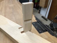
The yatoi hozo dovetail for the eave beam slides into its mortice on the back side of the barge board. The barge board is also housed to capture the end of the eave beam. Like this:
And backing out to see the barge boards give a better idea of what will happen when they are seated.
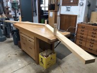
And a test fit last summer with the tie beams, eave beams, and ridge beams temporarily in place on saw horses.
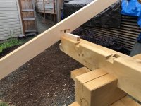
The ridge beam to barge board joinery is similar but instead of having a sloped ledge it has a small stub tenon and the joint is not housed. And the dovetail doesn't slide in from an open side but slips in horizontally. Here it is partially seated in a test fit.
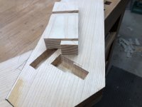
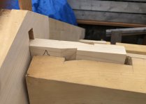
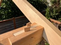
And skipping ahead chronologically, here is one barge board end assembled with the shachi sen tapped down and locking them in place. I will say that after taking this photo I climbed down the ladder and did a little victory dance.
The barge boards also have some clever and tricky-to-get-right joinery. I'll show that next.
These beams at 13 ft were too long to take to my shop machines for flattening so I did that with a Makita portable planer and hand planes. Here is one of the eave beams. The slots for the rafters I did with hand saw and chisels. The sloped ledge on the end is to support the barge board on the gable end. (I assume that barge board is the same term in England?)
That loose tenon with the dovetailed end is called a yatoi hozo or yatoi sen. I don't think there is anything like it in Western framing but it and multiple variations are common in Japanese woodworking where it is used for splice joints and some right angle connections as used here. I think It is worth a close look.
The yatoi hoze used here joins the barge board to the eave beam without metal fasteners. I used a slightly different version for the ridge beam to barge board joinery.
The yatoi hozo dovetail for the eave beam slides into its mortice on the back side of the barge board. The barge board is also housed to capture the end of the eave beam. Like this:
And backing out to see the barge boards give a better idea of what will happen when they are seated.
And a test fit last summer with the tie beams, eave beams, and ridge beams temporarily in place on saw horses.
The ridge beam to barge board joinery is similar but instead of having a sloped ledge it has a small stub tenon and the joint is not housed. And the dovetail doesn't slide in from an open side but slips in horizontally. Here it is partially seated in a test fit.
And skipping ahead chronologically, here is one barge board end assembled with the shachi sen tapped down and locking them in place. I will say that after taking this photo I climbed down the ladder and did a little victory dance.
The barge boards also have some clever and tricky-to-get-right joinery. I'll show that next.
GaryR
Nordic Pine
Cabinetman":2j6uv6l8 said:This is so very complex compared to a timber building from everywhere else, was it just the Earthquakes that necessitated it? Or is there just a bit of the Japanese psyche making things difficult deliberately?
What a lovely puppy!
I'm not an expert on Japanese culture by any means (I've been there once 40 years ago for a week of work) but I have read a little of the history of woodworking in Japan and can speculate. Most agree that their way of building temples was heavily influenced by Buddhists from China. But Japan remained mostly isolated for a long time. Their esthetic favored less ornate and more subdued designs. There were also laws called "sumptuary laws' that restricted the use of expensive materials like metal hardware to the elites. Japan had/has few iron resources. That meant that builders had to be extremely creative in their wooden joinery.
That is my 60 second understanding and could be completely misguided. But I agree it is a great question.

Such a shame that so much of the complexity will be forever hidden.
Mike G
Petrified Pine
GaryR":1psg07d3 said:......Here are the eave beams and how they relate to the tie beams and the rest of the frame.
View attachment 7
You're calling these eaves beams, which is fair enough, but here they are known as wall plates (any principal horizontal timber within a wall structure is known as a plate). Unless your roof has a structural ridge beam the weight of the roof will induce a turning moment on the wall plate/ eaves beam. Its a standard cause of failure in ancient rooves, with some rotting on the bottom outside of the plate and with rafters attached to (and thus applying force to) the top outside edge. Many, if not most 400+ year old timber buildings here will have some later blacksmith-made straps or brackets tying the top of this plate back to the storey posts or principal trusses.
(I assume that barge board is the same term in England?)
Yes, although it applies to covering boards rather than structural timbers. Those would just be called gable rafters.
The yatoi hozo dovetail for the eave beam slides into its mortice on the back side of the barge board. The barge board is also housed to capture the end of the eave beam. Like this:
View attachment 5
And backing out to see the barge boards give a better idea of what will happen when they are seated.
View attachment 4
And a test fit last summer with the tie beams, eave beams, and ridge beams temporarily in place on saw horses.
View attachment 3.....
Ah, right, so there is a structural ridge beam. This relieves the turning moment on the wall plate I mentioned previously. Good

I'm enjoying following this project. Can't help thinking it needs to have a more impressive name than 'shed' 
AJB Temple
Sequoia
- Joined
- Apr 15, 2019
- Messages
- 7,832
- Reaction score
- 1,299
What Mike said about roof twist is borne out in our own house. At one end of the house in particular, there has been a much later addition of some seriously thick, heavy duty and quite crude iron work bolted on to keep the roof lined up on the plate.
Regarding Japanese structures, the historical reasons are now largely speculation. Clearly earthquakes played a major part, as seismic activity is pretty constant there and it is well established that the joinery methods are very resistant to shake and heave. It's worth remembering that the volcanic ground was more suitable for surface rather than dug foundation methods too. But there must have been other factors at play as well. For example, the expectation of both houses and temples was that they would be rebuilt rather often. This was not usually due to collapse, but rather fire was a significant factor. The structures were also easily altered (standardised sizes based on mats) and extended. Rooms were not tied to specific uses necessarily.
From discussions I've had in Japan (limited by language) there is a further big difference. Ancient UK timber framing is almost always structurally overbuilt. Green oak twists and cracks and shrinks. So allowance was made by overbuilding and we still do this today. (Or at least I do - Mike probably doesn't as he has actual knowledge ).
).
In Japan though, with the exception of temples built somewhat in the Chinese style, wooden structures do not rely on overbuilding to acquire strength. Timber has always been fast growing and plentiful, and does not necessarily grow to great size, so there was a degree of necessity too for domestic building. The approach was not to make the building rigid - as our western approach tries to do, resisting movement - but to do the opposite and engineer for movement that would come from the ground anyway. It does not make sense to over spec the main structural timbers when that is your aim.
Regarding Japanese structures, the historical reasons are now largely speculation. Clearly earthquakes played a major part, as seismic activity is pretty constant there and it is well established that the joinery methods are very resistant to shake and heave. It's worth remembering that the volcanic ground was more suitable for surface rather than dug foundation methods too. But there must have been other factors at play as well. For example, the expectation of both houses and temples was that they would be rebuilt rather often. This was not usually due to collapse, but rather fire was a significant factor. The structures were also easily altered (standardised sizes based on mats) and extended. Rooms were not tied to specific uses necessarily.
From discussions I've had in Japan (limited by language) there is a further big difference. Ancient UK timber framing is almost always structurally overbuilt. Green oak twists and cracks and shrinks. So allowance was made by overbuilding and we still do this today. (Or at least I do - Mike probably doesn't as he has actual knowledge
).In Japan though, with the exception of temples built somewhat in the Chinese style, wooden structures do not rely on overbuilding to acquire strength. Timber has always been fast growing and plentiful, and does not necessarily grow to great size, so there was a degree of necessity too for domestic building. The approach was not to make the building rigid - as our western approach tries to do, resisting movement - but to do the opposite and engineer for movement that would come from the ground anyway. It does not make sense to over spec the main structural timbers when that is your aim.
AJB Temple
Sequoia
- Joined
- Apr 15, 2019
- Messages
- 7,832
- Reaction score
- 1,299
PS Gary. Please will do a thread on your Japanese tools and your thoughts on them. I posted about this last night, but it was somehow lost.
I have a good selection of Japanese tools, including big slicks and super nice chisels acquired in Japan. And I don't get on with them at all working in oak framing timbers. Different steel and need for a more brutal approach in dry oak perhaps.
J planes don't work for me at all cleaning up oak tenons.
I have a good selection of Japanese tools, including big slicks and super nice chisels acquired in Japan. And I don't get on with them at all working in oak framing timbers. Different steel and need for a more brutal approach in dry oak perhaps.
J planes don't work for me at all cleaning up oak tenons.
BigMonka
New Shoots
This "shed" is built much more like an intricate puzzle box than a shed! I've long had an interest in UK style oak framing, so this is fascinating to see a completely different approach to crafting a timber building. Thanks for taking the time to share your build :eusa-clap:
Mike G
Petrified Pine
AJB Temple":ta51bwu3 said:.....For example, the expectation of both houses and temples was that they would be rebuilt rather often.....
This is really important. I've had this discussion with one or two proponents of eastern building techniques over the years, who have made the claim that the Japanese/ Chinese/ Korean timber buildings outlast western timber buildings despite being made of softwood, and that this must be due to superior.........something. Well, the fact is that all the long-lived buildings they point to as examples are high status buildings belonging to rich institutions which have survived as long as the buildings. Temples and palaces are the classic examples. The stability of the institutions which own them mean they have been maintained, repaired, and indeed rebuilt throughout their lifetime. To compare that with British cottages is meaningless, because even higher status domestic buildings such as manor houses have been through cycles of boom and bust (and civil or religious war), meaning at best there were long periods where they were no more than patched up with ad hoc repairs, but were sometimes entirely neglected for a couple of centuries.
GaryR
Nordic Pine
AJB Temple":36d349j7 said:The approach was not to make the building rigid - as our western approach tries to do, resisting movement - but to do the opposite and engineer for movement that would come from the ground anyway. It does not make sense to over spec the main structural timbers when that is your aim.
All good points that I've read about, too.
One source I have says that in Kyoto there used to be a profession roughly translated as "house straightening carpenter." These guys would be called in after an earthquake to pull back into plumb a house left leaning but not broken. Get it straightened, tighten the wedges, then call in the window and door maker to re-do all those parts that probably exploded when the frame racked. Cheaper than building a new house.
GaryR
Nordic Pine
Mike G":yumu061c said:AJB Temple":yumu061c said:.....For example, the expectation of both houses and temples was that they would be rebuilt rather often.....
Well, the fact is that all the long-lived buildings they point to as examples are high status buildings belonging to rich institutions which have survived as long as the buildings. Temples and palaces are the classic examples. The stability of the institutions which own them mean they have been maintained, repaired, and indeed rebuilt throughout their lifetime. To compare that with British cottages is meaningless, because even higher status domestic buildings such as manor houses have been through cycles of boom and bust (and civil or religious war), meaning at best there were long periods where they were no more than patched up with ad hoc repairs, but were sometimes entirely neglected for a couple of centuries.
I agree. One astonishing statistic I read is that the typical lifespan of a Japanese house is only 30 years. The reasons are complex but nevertheless the point remains that only the "important" buildings are maintained. At great expense.
GaryR
Nordic Pine
Barge board joinery. In Japan the name for this member is hafu or hafu-ita, 破風板 . "Ita" means board.
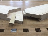
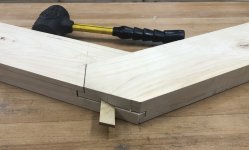
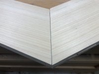
There are several joints that can be used. I chose one of the simpler ones. It is basically a splice joint but oriented at an angle.
Here is the view of a test joint in scrap from the back showing the two boards and the shachi sen that will lock them together.
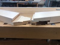
Here is the real joint from the front during final fitting.
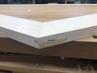
The goal is have a clean mitre showing on the front. Actually, a subtlety of the design is that there should be a slight gap at the peak, about 1-2%. After installation, the weight of the roof materials will press down on the joint and close it up. If you don't allow for that, then the joint will open on the bottom. My OCD didn't let me intentionally leave any gap. Here in one joint before tapping in the shachi sen, which tightened that remaining half a mm.
Edit: I remembered I have a short video of assembling the barge board joint:
https://www.youtube.com/watch?v=VyUib2bJ5wk
The ridge beam I've already partially shown. It has pockets sawn and chiseled to receive the rafters. You can see from the size that the rafters are small dimensioned. I used 50 mm x 65 mm in section, spaced on 1 ft centres. Alternate joinery has the rafters just sitting on the ridge beam, or sitting on a ledge instead of pocket mortices. The morticed joint is more work but looks cleaner from below and helps resist rafters twisting. Test fitting here.
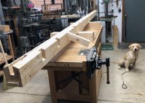
I was skeptical about how much load they could carry (as apparently was Willa). But their maximum span is only about 3 ft, there are a lot of them, the roof materials are fairly light (metal panels rather than heavy tiles) and my climate doesn't require planning for heavy snow loads. I did the calculations and I think they will be fine.
There are several joints that can be used. I chose one of the simpler ones. It is basically a splice joint but oriented at an angle.
Here is the view of a test joint in scrap from the back showing the two boards and the shachi sen that will lock them together.
Here is the real joint from the front during final fitting.
The goal is have a clean mitre showing on the front. Actually, a subtlety of the design is that there should be a slight gap at the peak, about 1-2%. After installation, the weight of the roof materials will press down on the joint and close it up. If you don't allow for that, then the joint will open on the bottom. My OCD didn't let me intentionally leave any gap. Here in one joint before tapping in the shachi sen, which tightened that remaining half a mm.
Edit: I remembered I have a short video of assembling the barge board joint:
https://www.youtube.com/watch?v=VyUib2bJ5wk
The ridge beam I've already partially shown. It has pockets sawn and chiseled to receive the rafters. You can see from the size that the rafters are small dimensioned. I used 50 mm x 65 mm in section, spaced on 1 ft centres. Alternate joinery has the rafters just sitting on the ridge beam, or sitting on a ledge instead of pocket mortices. The morticed joint is more work but looks cleaner from below and helps resist rafters twisting. Test fitting here.
I was skeptical about how much load they could carry (as apparently was Willa). But their maximum span is only about 3 ft, there are a lot of them, the roof materials are fairly light (metal panels rather than heavy tiles) and my climate doesn't require planning for heavy snow loads. I did the calculations and I think they will be fine.
Mike G
Petrified Pine
What you're calling a splice joint we would call a scarf*. The beauty of all the Japanese joints for this location is their resistance to twisting.
As an aside, it is staggering how much difference a birdsmouth makes to the forces in a roof, so having a horizontal base to the housings for the rafters, and putting a birdsmouth on the underside of the rafters, would have made this an even better roof structurally.
Your bench-dog shows how long this epic build took!
*As a silly nod towards the brilliant artist responsible for much of Pink Floyd's later art work, and for many brilliant political cartoons including the start of "Yes Minister", I used to always mis-spell this "scarfe". Nobody picked up on it, so it wasn't worth doing....
As an aside, it is staggering how much difference a birdsmouth makes to the forces in a roof, so having a horizontal base to the housings for the rafters, and putting a birdsmouth on the underside of the rafters, would have made this an even better roof structurally.
Your bench-dog shows how long this epic build took!
*As a silly nod towards the brilliant artist responsible for much of Pink Floyd's later art work, and for many brilliant political cartoons including the start of "Yes Minister", I used to always mis-spell this "scarfe". Nobody picked up on it, so it wasn't worth doing....
AJB Temple
Sequoia
- Joined
- Apr 15, 2019
- Messages
- 7,832
- Reaction score
- 1,299
:text-+1: Totally agree Mike. I've heard people say very similar things about ancient Japanese temples. It's total nonsense as they have practically all been rebuilt in whole or in part (ie reclaimed parts) numerous times. The Japanese themselves don't make these daft claims: they acknowledge that rebuilds are a fact of life. It does not stop them calling a pre-Edo/Tokugawa temple 15th Century or whatever, because the essence and spirit of it really does have that history. The fabric (wood etc) definitely does not.