• Hi all and welcome to TheWoodHaven2 brought into the 21st Century, kicking and screaming! We all have Alasdair to thank for the vast bulk of the heavy lifting to get us here, no more so than me because he's taken away a huge burden of responsibility from my shoulders and brought us to this new shiny home, with all your previous content (hopefully) still intact! Please peruse and feed back. There is still plenty to do, like changing the colour scheme, adding the banner graphic, tweaking the odd setting here and there so I have added a new thread in the 'Technical Issues, Bugs and Feature Requests' forum for you to add any issues you find, any missing settings or just anything you'd like to see added/removed from the feature set that Xenforo offers. We will get to everything over the coming weeks so please be patient, but add anything at all to the thread I mention above and we promise to get to them over the next few days/weeks/months. In the meantime, please enjoy!

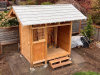
A Japanese style garden shed

MattS":1ufjltor said:
Never seen anything like those flower rain chains, they’re beautiful.
Rain chains are great but unfortunately you need a roof with a very large overhang for them to be effective, which we don't have on our house. National Trust shops sell a rain chain at a reasonable price:

https://shop.nationaltrust.org.uk/rain- ... -rust.html

Not especially ornate and I don't know what the material is but I was surprised to see them in the shop at Stourhead - Rob
 
They are steel in that link. Cheap for a basic one just as an ornament though.

Why do you say they need a big overhang Rob? Splash back? I realise that most Japanese rooves that have these most likely do have a large overhang.

The type I am interested in uses multi link chains as well as the cups, to create flow. They may well splash more than I thought. One of the newer buildings at RHS Wisley ( I think it is there, but it may be the new RHS site north of London), might be the newish library building, uses rain chains instead of downpipes. Just straightforward thick link galvanised chain. It wasn't raining when we were last there though.
 
The only splash comes from the bottom. Water just runs down chains in a neat and tidy way. So long as the bottom of the chain is detailed properly, and is far enough away from the building, there should be no issue with splashing. I suspect the roof overhangs are tradition, and to do with aesthetics as much as practicality, although keeping the base of wooden buildings dry as much as possible has obvious benefits, and a big overhang will keep a lot of rain off the walls.
 
AJB Temple":1a0relxx said:
They are steel in that link. Cheap for a basic one just as an ornament though.

Why do you say they need a big overhang Rob? Splash back? I realise that most Japanese rooves that have these most likely do have a large overhang.

The type I am interested in uses multi link chains as well as the cups, to create flow. They may well splash more than I thought. One of the newer buildings at RHS Wisley ( I think it is there, but it may be the new RHS site north of London), might be the newish library building, uses rain chains instead of downpipes. Just straightforward thick link galvanised chain. It wasn't raining when we were last there though.

Splash back I guess or else the brickwork on a Western house would be continuously wet when it rained and the effect wouldn't be quite the same. The ones I've seen in Japan are even plastic on ordinary houses but they're sited well away from the walls of the house due to the very large overhang. Most effectively seen at the corners of temples and shrines with their vast roofs and overhangs - Rob
 
I've never seen plastic. We did go to a village near Kyoto on an overcast day. Name escapes me. The riverside houses had water running through rills in the kitchens, and most of them were plain timber walled houses, some with chain gutter downpipes and some wooden gutters and downpipes. It rained heavily in the afternoon and the chains were pretty effective at carrying the roof water away. From memory the overhangs were about 2ft at plate level.

My application is an outdoor kitchen in the Japanese garden. It would be largely decoration as there is already an 18" overhang (roof is cedar shakes over oak) and there are no gutters but the inside stays dry except in heavy wind. I had originally intended to make wooden gutters but, you know, list of jobs. :?

In my case the chains would run to water collection troughs.
 
Now then, where was I? Oh yes, the windows.

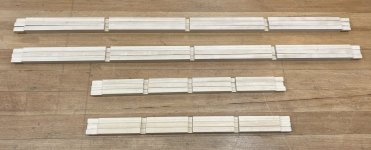
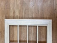
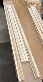
I got the lap joints done for the lattice/kumiko. I'm following the methods Desmond King recommends in his books on making shoji and kumiko. It starts with dimensioning all the kumiko to as close to the same thickness as you can get. In my case, 9.0 mm was the target, plus a little to allow for finish planing

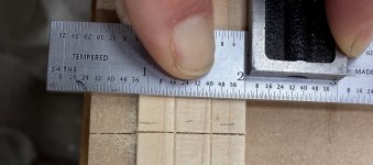
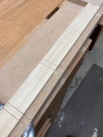
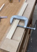
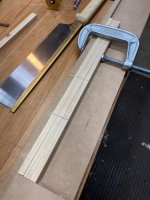
Do all the layout on a story stick first. Then use that to knife lines for one side of the lap onto the kumiko pieces. Pencil a tick mark on the side of the line to be cut. Gang the pieces in a holding jig to keep them registered. Here are three horizontal pieces for one window.
B47AA117-AAD4-44F2-B6E1-027F60465043_1_201_a.jpeg

Cut along the lines to a depth of half the kumiko.

D9D32DB6-BF5E-4567-B7DC-45B810806070.jpeg

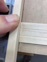
Then flip the jig around 180 degrees. Use a square to line up a piece of kumiko so that its right side just covers the kerf. Here the kumiko is almost in place. After the photo I moved it over a bit more.

31AC3917-D1FA-438D-AF1C-C73088043359.jpeg

Hold the square in place, remove the kumiko, and knife along the square to establish the other side of the lap.

DEE21345-2597-469A-99E7-795C214DE95A_1_201_a.jpeg

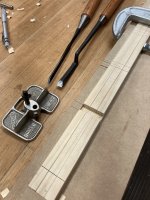
Saw on the inside half of the line as before. Remove the waste with a chisel. I cleaned up the base of the lap with a small router plane to ensure a uniform depth.

24A547D4-53DB-450A-A7D3-63FC603328C2.jpegCF014A84-0886-484B-8948-CDE45E01E20F_1_105_c.jpeg
56165BDB-9B50-4E38-B6AE-4C89F7DA4104_1_105_c.jpeg


Repeat for the other kumiko pieces. They should end up just three or four plane shavings too tight.
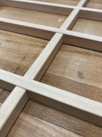
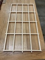
Check the fit and adjust where needed. Add a dab of glue to the sides of the laps and tap them home. In this case the verticals are intentionally 1 mm proud of the horizontals and all the kumiko are beveled on their front faces.

F2AD87AE-08B2-421F-B34E-5B2AEDEEBFCB_1_105_c.jpeg

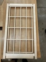
The kumiko were previously tenoned to fit through a perimeter frame called a tsukeko. According to King the tsukeko is optional but adds a degree of refinement. The tenons are long enough to pass through the mortices in the tsukeko and into mortices previously chopped into the rails and stiles. Getting all of those mortices layed out to line up precisely is work to be done when your are fresh. I think I have them mostly right.


ADF17F33-A167-41C8-B3A0-2D67B10A019E_1_105_c.jpeg

And how it will all come together.

CA5C9DDD-79BF-498B-A096-BDBF439E5DE5_1_105_c.jpeg

I'm going to leave it at this stage for awhile since I still need to chop mortices for the metal rollers and a inset pulls. I have them on order.
 
The design may be very eastern, but the technique is universal. Nice to see it being done by hand.

The real skill in this sort of work isn't the joints, but in preparing the stock. Accurately planing thin material is difficult, although a "thicknessing" planing jig is easily imaginable.
 
Great to watch and thanks for sharing. I cannot see me ever having the patience for the methods you have shown here throughout the whole build.
 
Mike G":18hn9rwe said:
The design may be very eastern, but the technique is universal. Nice to see it being done by hand.

The real skill in this sort of work isn't the joints, but in preparing the stock. Accurately planing thin material is difficult, although a "thicknessing" planing jig is easily imaginable.

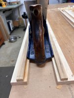
I would agree with that. Getting the lattice stock to a uniform thickness by hand planing is not easy. Machines are probably much better for this task. But I don't have those machines.

My planing jig worked mostly OK but did produce some snipe at one end. Starting with longer stock than necessary allowed me to trim that part away.

0CB0F412-4ACB-4648-B7F1-7B813526212D_1_105_c.jpeg

E0A32FB7-F692-49B3-BE41-F5DE5C75824B_1_105_c.jpeg

The problem with this method is keeping the stock absolutely flat. If it wants to bow then the thickness can vary quite a bit as the stock either digs into the blade or dips below it. My solution was to check carefully with calipers along the length to gauge my progress. Doable for the handful of kumiko here but beyond tedious for preparing many multiples.

There are special planes that include a pressure bar just ahead of the plane mouth to eliminate that issue. But they are very expensive and a kind of one trick pony. Desmond King writes that he usually uses a drum/thickness sander.
 
Yes a successful outcome and nice proportions too.
I sold an old saw that I don’t have time to bring back to life. I got talking to the guy who bought it, a man seriously into his big woodwork cast iron here in Pennsylvania. obviously we started to show each other pics of workshops and there it was, another Morticer the same as yours still working well and earning its keep, just not quite as pristine as yours though Gary, he thought it was so cool you having all the provenance for yours.
Ian
 
Cabinetman":1vcuptbf said:
Yes a successful outcome and nice proportions too.
and there it was, another Morticer the same as yours still working well and earning its keep, just not quite as pristine as yours though Gary, he thought it was so cool you having all the provenance for yours.
Ian

That's incredible! There were so few made and fewer left standing. It would be fun to touch base with him.

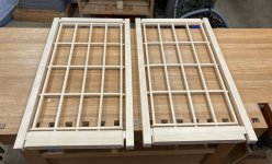
Second window to the same stage.FD5A1290-BFDF-435E-91F3-CBFC23434E43_1_201_a.jpeg

I'm going to take a break for a few weeks to work on some other projects. But I'll be back.
 
Taking a break from such intricate work I can understand. The guy with the morticer and I are going to keep in touch so I will talk to him about that, I think you said there were production nr’s on them? I recognised it straight away from the curved arms, he did say he thought it was made in 1914.
Ian
 
Back at it. A woodworker friend who knows Japanese kindly ordered me some rollers for the windows and doors and they arrived this week. I had a lot to choose from: the catalog was more than 240 pages of just window and door rollers! All written in Japanese, of course, but with plenty of pictures, and tables with the metric dimensions and load ratings most important of all, the price.

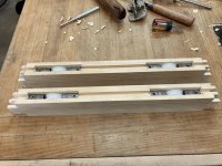
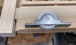
For window rollers I chose these with stainless steel carriages, ball bearing wheels, and nylon rims. For scale the wheels are 40 mm in diameter.

45A9EE9B-2DD8-4B14-879E-F96FAB34C5E6_1_105_c.jpeg

And here they are morticed in place. I still need to screw them in but I'm waiting until I fit the windows to the jambs in case they need adjustment.

5FE78393-29C4-44FD-A832-3D1736F33B50_1_105_c.jpeg

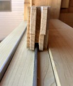
And riding on a track. The nylon is very quiet and the ball bearings run smoothly. The rail bottom will get a slight bevel to match the sill/cill.

BD3CDF27-449F-4F98-B52E-FF8FF837357B_1_201_a.jpeg
 
Looks very good Gary, I presume that’s a window frame so not as tall, on the door I think I would get as much distance between the wheels as possible even down to removing the stainless where the screw goes on the outside ends, unless the door is a wide one of course. You are probably thinking what’s he on about? I worry that the door will tilt over the leading wheel when pulled, and the top opposite corner will catch at the top, though I’m sure it’s something the Japanese have long ago dealt with.
Neatly done, how is the track fitted? Is it just a tight fit?
Ian
 
I understand the concern. The mortice for the rollers is fairly deep and I didn't want to get it too close to the root of the tenons thinking it might weaken them.

The entire length of the window top rail has a tongue that rides in a groove in the upper jamb. The fit is done so that the window can lift up into that upper jamb groove then drop down onto the roller track. At least that is the theory. We'll see if I have it done the layout/set out correctly.
 
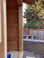
Today I finished installing the exterior door and window jambs (except for a few plugs for screw holes)

A971A01C-0DA5-494E-83F6-12F99D45D161.jpegD2C10BEF-BF85-445F-BDD9-05C687F6CC50.jpeg553705D8-3BED-4959-AAB7-1708AB94CD9F.jpeg

The window jamb is perfectly square and level and plumb. The door jamb is level and plumb and lines up perfectly with the posts but the diagonals are off square about 6 mm over 3 m. After a bit of head scratching I decided that the shed frame itself is off by that much, which shifts the upper jamb slightly to the left compared with the lower jamb. I don't think there is much I can do about that at this point since in the building method the shed frame is the inner door jamb and and I'd like the exterior jamb reveals on the post to be equal and not taper. Instead, I plan to make slight adjustments to the door stiles to accommodate unless someone has a better idea. The doors don't have to be weather tight but I'd like them to move smoothly without binding.
 
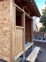
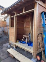
More small steps. Ha ha. I've added some temporary steps to make it easier for my aging legs to hop up the half meter rise from grade to floor. To be replaced by stone slabs in the future.


945EB73F-8634-4B5E-9E67-FDA6D476E407_1_201_a.jpeg

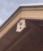
And after adding a little more detail and relief to the gable pendants I mounted them.

66F22579-5028-4D81-A509-A4707CABB546_1_201_a.jpeg
13C49086-A4DC-41D9-AC85-B3F9AB9098AB_1_201_a.jpeg
 
Yes nicely done, the sticking out bit reminds me of young children’s wooden nuts and bolts that come with a wooden screwdriver and spanner, don’t suppose you threaded them together Gary? lol.
 
Nope, not threaded, but that center post does go through and becomes a tusk tenon on the back side. I'd take a picture but it is now 10 feet in the air.

Here is the model I used for the gable pendant:

umebachi gegyo.jpeg
 
Cabinetman":2aoecrr4 said:
They have a very nice action Gary, they’re called Yorkshire sashes here btw.
Ian

Horizontal sliding sashes in this neck of the woods.
 
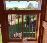
In the video the right hand one shows a distinct gap to outside when closed. Are they meant to slide into a rebate to keep the rain out? or will a bead be added? Presumably there will be some sort of lock to stop the wind rattling them open?
 
AJB Temple":2zxnkb1v said:
In the video the right hand one shows a distinct gap to outside when closed. Are they meant to slide into a rebate to keep the rain out? or will a bead be added? Presumably there will be some sort of lock to stop the wind rattling them open?

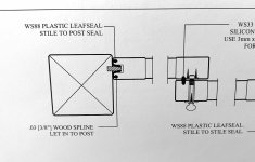
There is a spline let into the post and there will be a matching groove in the window stile. I waited to do the groove until after I made sure the window fit so you are seeing the stile face bumping the spline. The scheme looks like this:

6E510B6F-14EA-4437-8E66-FFE3A30DCB24_1_201_a.jpeg

I'm also waiting to do any weather stripping until after I see whether it is actually necessary. The window is well sheltered under the eaves and the shed is, well, a shed. A little wind or mist filtering through may not matter.
 
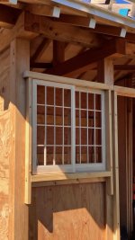
Oops. I was wondering why the outside sash didn't quite fit while the inside sash did. I knew the jambs were square and plumb and the windows themselves were square within a mm on the diagonals. After some head scratching I decided to reverse the windows left/right and discovered this:4CB3B476-DBBB-444B-A914-A88D360F9E95_1_201_a.jpeg

Notice the large gap between the two sashes at the top. That's because I rebated the outside face of the sash instead of (as I was supposed to do) the inside face. I had it drawn correctly but when it came time to lay out the rebate I wasn't paying attention and did the two sash identically.

For a fix I found some matching stock and filled in the rebate. It is a good match but doing it this way lays the ends of the filler strip over the stiles instead of butting into them. I think that is OK since only a couple of mm along the bottom of the filler will be visible once the new tongue fits into its groove in the upper jamb. And it will be far above a normal line of sight. Not perfect but a reasonable alternative to making a new sash.

6A2E3578-2E05-44F0-8577-D9B25FCD45E6.JPG1E7B2281-8AA3-4BBF-AC35-93A775008DE3.JPG
 
That sash was cursed.

I ordered the glass for the two sashes. The glass for the other sash fit perfectly. The identical pane for this one did not. It seems that during glue-up I had skewed the clamps enough to skew the sash so it was a trapezoid instead of a square. By about 3/16" ~5 mm top to bottom. And very solidly glued with Titebond III. I tried a few methods to dissolve TiteBond III on some scraps with no success. I decided to bandsaw it apart and save the lattice, which worked. Now on to making a replacement sash.
 
I was just about to ask how much of the original wood remained once you rebated the correct side..........but as it's gone on the firewood pile it's no longer relevant.
 
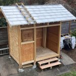
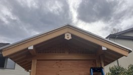
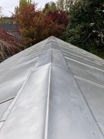
I finally, after many weeks of delays, finished the roof cladding. Well, actually my neighbour did most of the roof work with me cheering him on from the safety of the ground. Although I did do all of the sheet metal cutting and bending.

In the end I'm 50:50 on the esthetics but I can say that it looks to be a solid design, especially for my climate. Yesterday was warm, dry and clear with direct sun on the roof for several hours and it was only mildly warm to the touch. I can't imagine how water will get through the cladding except for possibly blown by horizontal winds, and the rain will have to face a double layer of water-resistant barrier and few nail holes.

We finished just before it started to rain again which appears as the slight dappling seen in the first picture.


View from our kitchen, the ground, and from the gable end. And celebratory beverage.

E2B2C06D-2466-4A74-B645-5BEED64AFF30_1_105_c.jpeg8CAFF83F-D2C1-40AF-B772-2885BC356770_1_105_c.jpeg7A6B3AE3-855D-466F-B28E-68E088FF466D_1_105_c.jpeg

F8327BCF-8671-4DC9-8984-010C3E702193_1_201_a.jpeg
 
Why different renders inside and out?
Simply put, It's an experiment, like the rest of the project. Earth plaster is a typical old school finish indoors in Japan, and can be used outdoors but isn't quite as durable in a wet climate. Lime plaster is more durable outdoors but as I understand it more difficult to work with. Never having worked with either before I thought I would try both.
 
Lime is dead easy to work with....so long as you have a good weather forecast. You want it dry for a week, and not too hot or cold. Get the weather right and it's pretty difficult to get the lime render wrong.
 
Shall follow the earth plaster with interest.....

So shall I. It wasn't a roaring success in the only building I've ever specified it for. It shrinks as it dries, and the wetter it is, the more it shrinks. So, apply it as dry as you dare........and then it's difficult to work. The builder thought they'd got a good finish, and came back after the weekend to find it had crazed all over. The area here is so tiny that it will work fine, but I'd be cautious if it was a bigger project.
 
Back
Top