I've had quite a productive afternoon, so I think I'll spread the work over a couple of forum posts, one now and one tomorrow morning probably.
The first thing I wanted to get on with was mounting the inverter (aka variable speed drive, aka variable frequency drive).
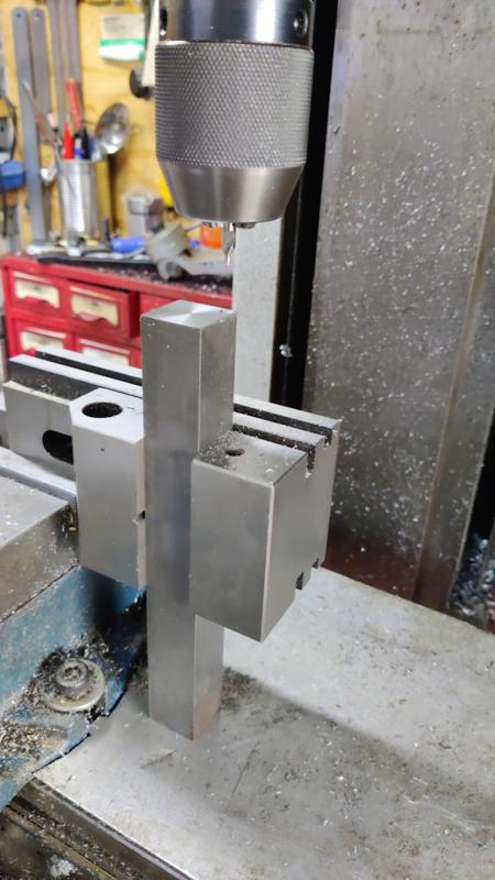
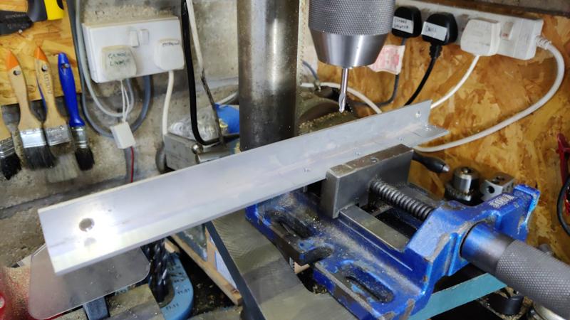
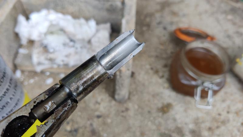
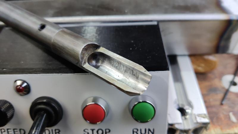
A couple of days ago, I 3D printed a little marking gauge to allow me to mark a pocket in a bit of 40 mm deep aluminium angle:
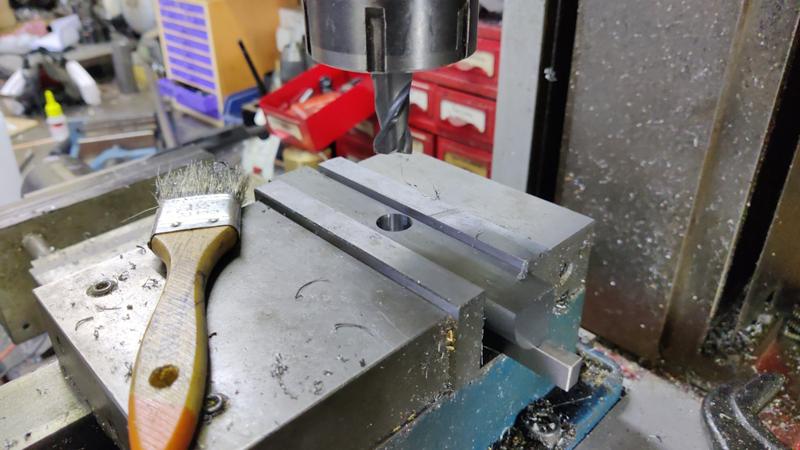
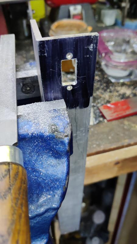
To hollow out the shape, I used a drill bit (not especially accurately) to get rid of the bulk of the waste and then filed it until it was looking okay-ish:
I then drilled some mounting holes, including a bonus extra one that I drilled in completely the wrong place!
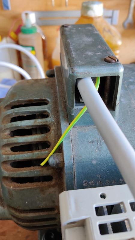
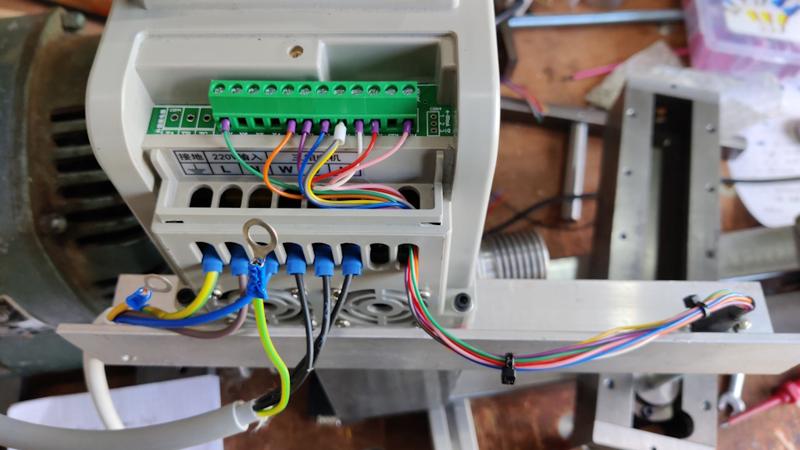
Before mounting the inverter to the motor plates, I fitted what will be the final bit of wire to the motor and trimmed it to length. There isn't anywhere very obvious to attach the earth wire to the motor, so I'm still pondering what to do about that as it seems sensible to have a decent earth connection.
Using a multimeter on continuity test mode, it buzzes through okay from the spindle shaft to the inverter earth and all the way to the bed, so it's probably okay without that extra connection, but I still think I'll probably attach it to a screw hole somewhere in due course.
There was then a very tedious exercise of doing lots of cutting, stripping and crimping of wires. I'm an electronics engineer by profession, but I find wiring intensely dull.
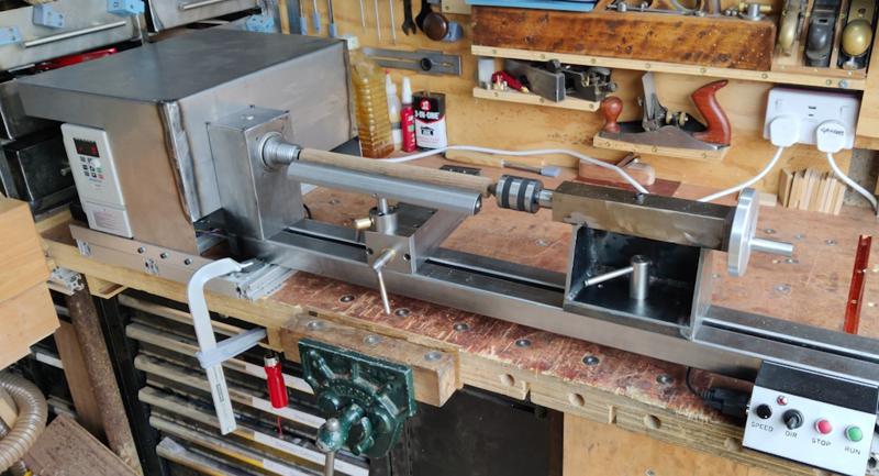
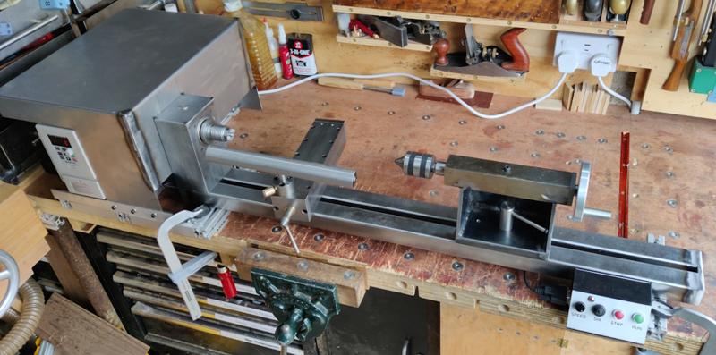
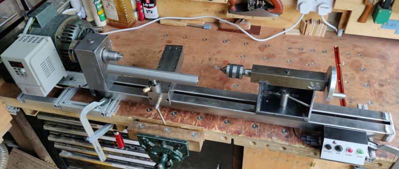
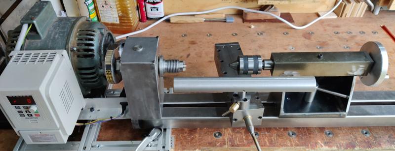
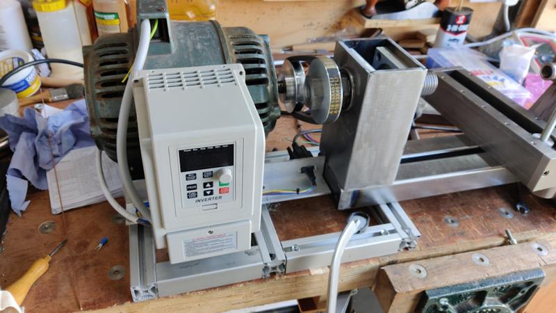
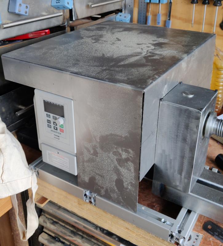
With that done, I could finally mount the inverter through the motor mount plates (with slightly longer screws than were there before), so the inverter slides back and forth with the motor.
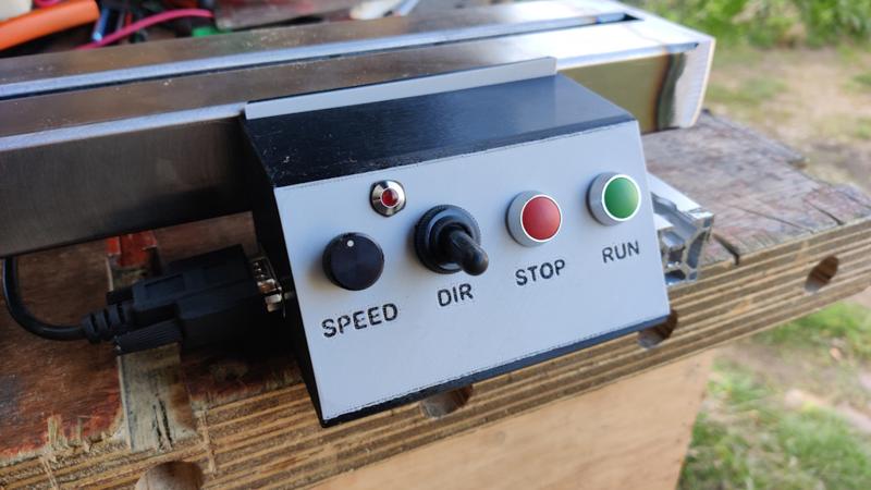
Another little 3D-printed creation was a little control panel to sit at the right-hand end of the bed, connected to the inverter with an old 9-way serial cable extension lead (held to the bed with some M4 rivnuts and some cable tie mount things):
It all seems to be working okay when powered on. It took me a while to figure out how to configure the remote controls. The manual for the Jaguar Cub inverter I have on my metalworking lathe is 171 pages long. The one that came with this cheap unbranded inverter is two sides of A3 and I've already found a couple of mistakes in it! Anyway, after fiddling and experimenting for a while, I got it all set up okay.
There are a couple of things that don't work quite as planned. The little LED on the control panel is one with a built in flasher. I fitted one of those to the control panel on my metalworking lathe, wired up such that it flashes when the inverter is configured to run the lathe backwards. I wanted to do the same here, but the LED needs 24 V to come out of the inverter and this one only supplies 12 V. I haven't decided whether I think it's worth the effort to do anything about that.
The other thing which doesn't work quite right is the speed control. I've got the inverter configured for maximum frequency of 120 Hz. If I set it up to derive the speed from the control panel potentiometer, it runs from 0 to 120 Hz. If I switch it to use the remote potentiometer, it runs from 0 to 60 Hz. The manual shows the potentiometer supply voltage as "10 / 5 V". My inverter supplies 5 V for the potentiometer, so I wonder if the power supply output is 5 V but the potentiometer is expecting to run from 0 to 10 V!
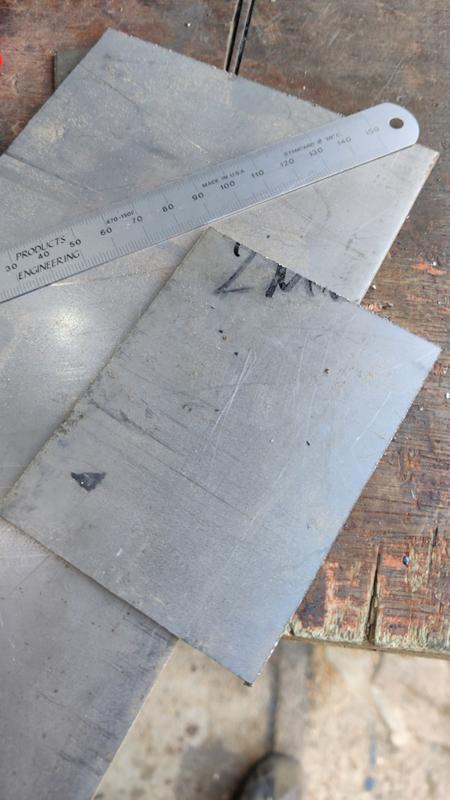
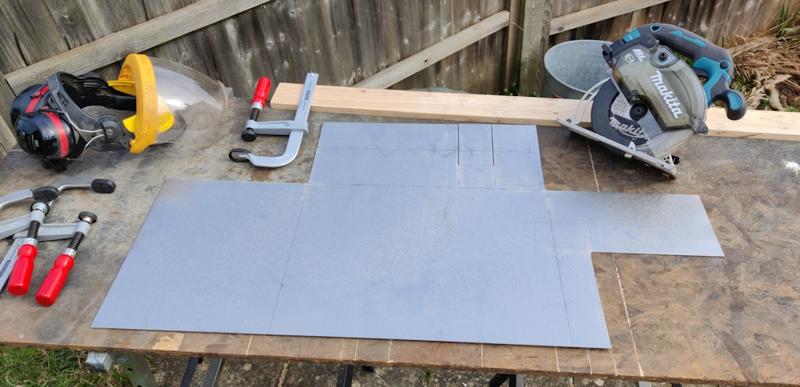
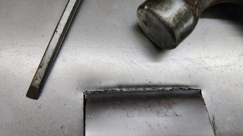
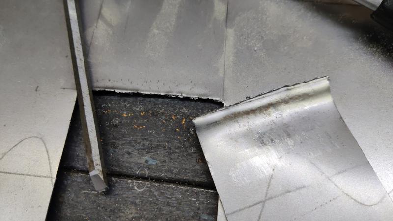
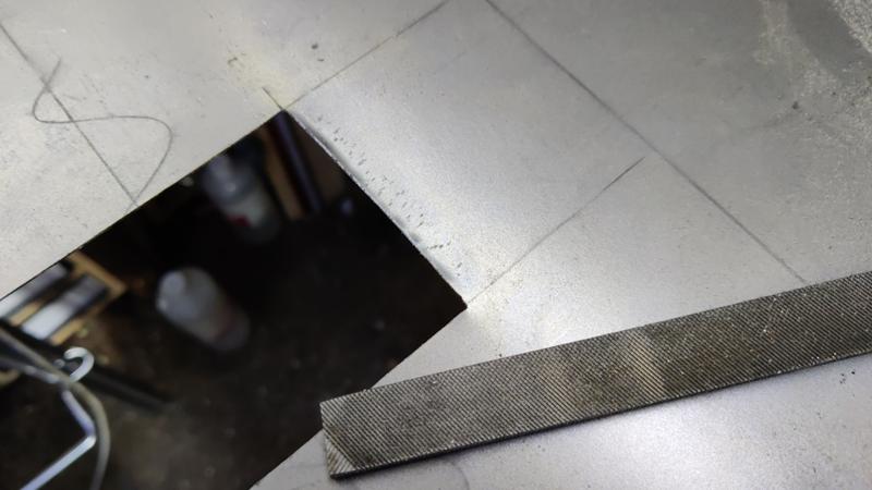
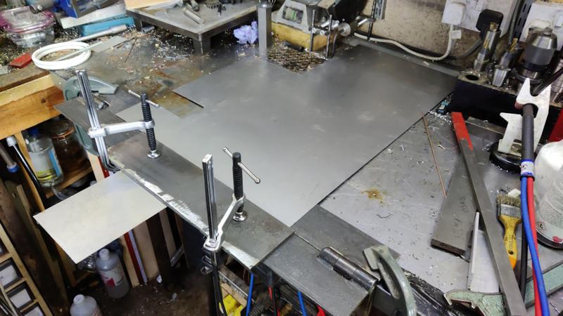
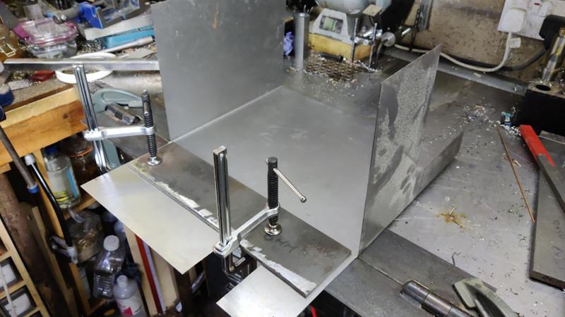
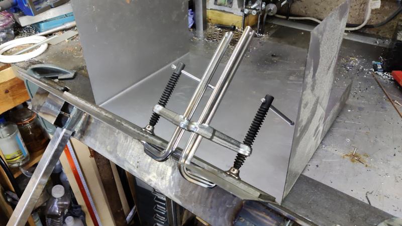
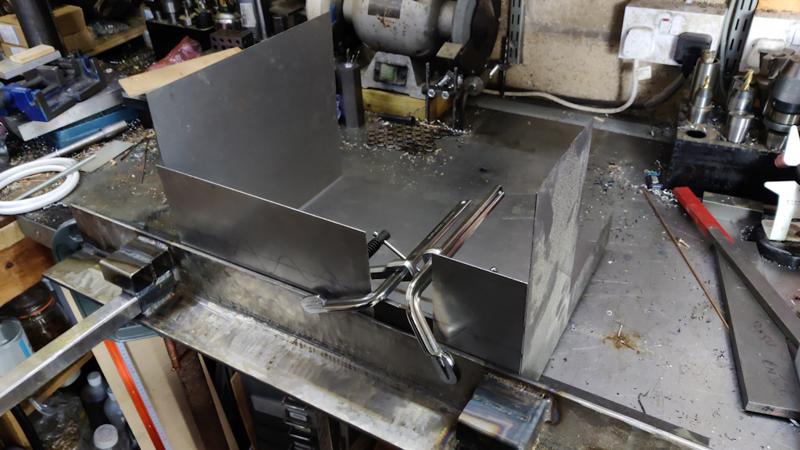
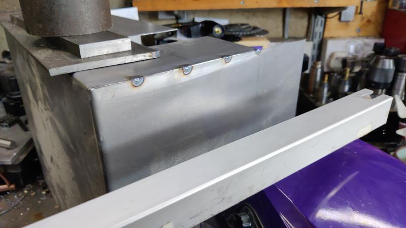
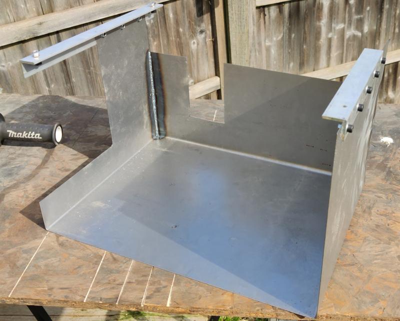
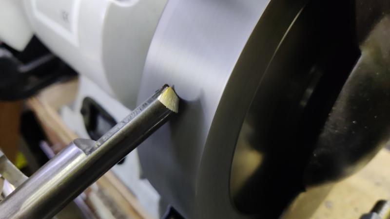
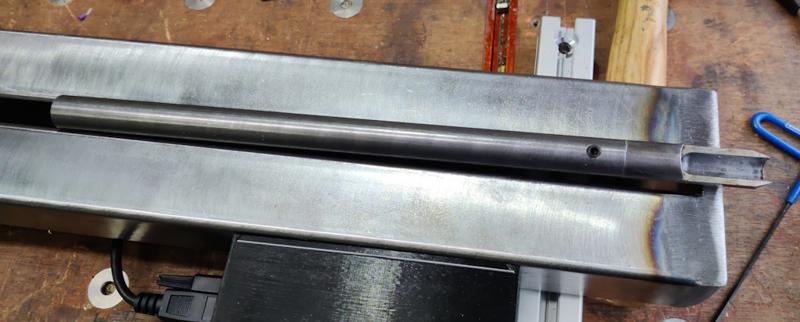
The next job I got on with was making a lid for the headstock (to stop it filling up with sawdust). I started with a bit of 2 mm plate (probably stainless steel, but I'm not sure) and chopped it roughly to size with the metal cutting circular saw:
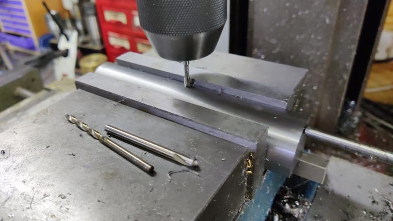
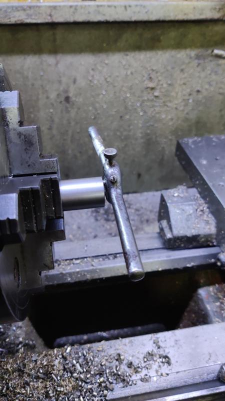
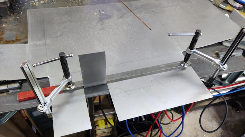
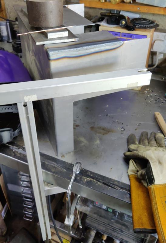
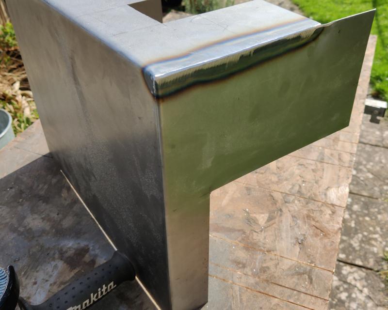
I then used some transfer punches to mark the location of the mounting holes and measured the location of the hole needed for the tommy bar (used to lock the spindle and allow a chuck or the pulley/bearing nuts to be tightened/loosened). They were drilled and then the lid was attached to the headstock and ground to fit with a flap disk in an angle grinder, not worrying too much about perfection!
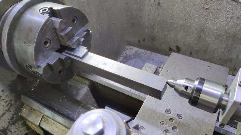
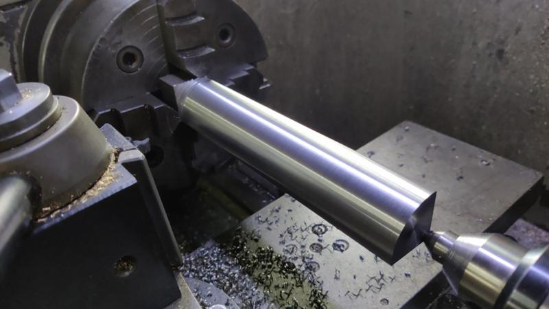
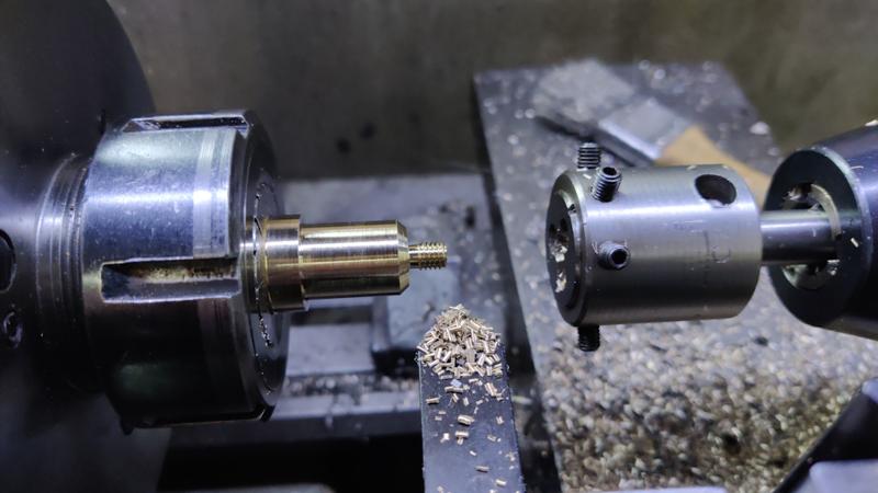
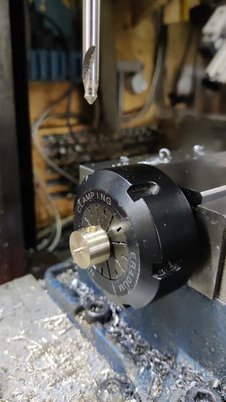
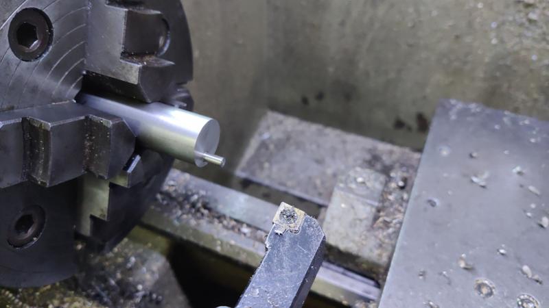
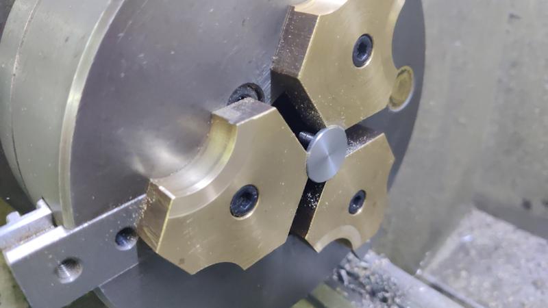
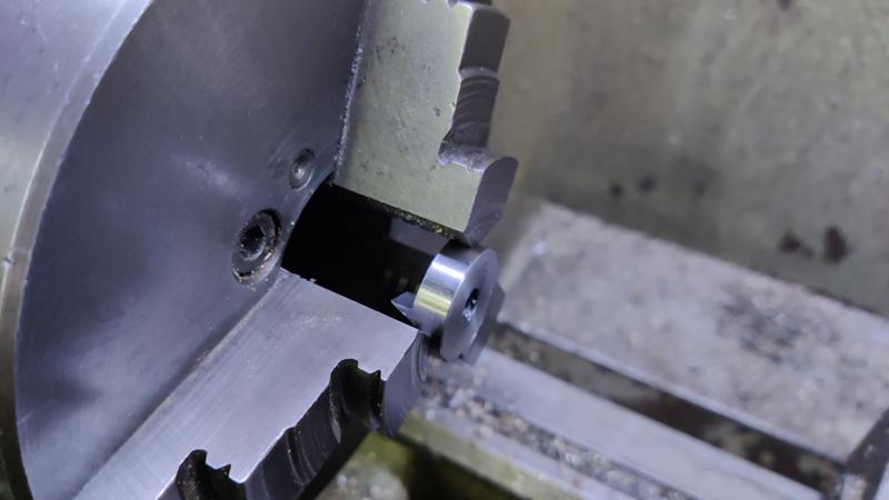
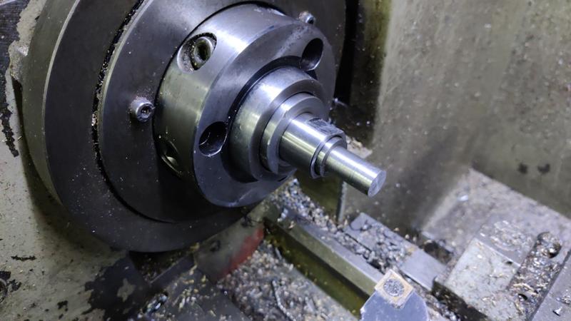
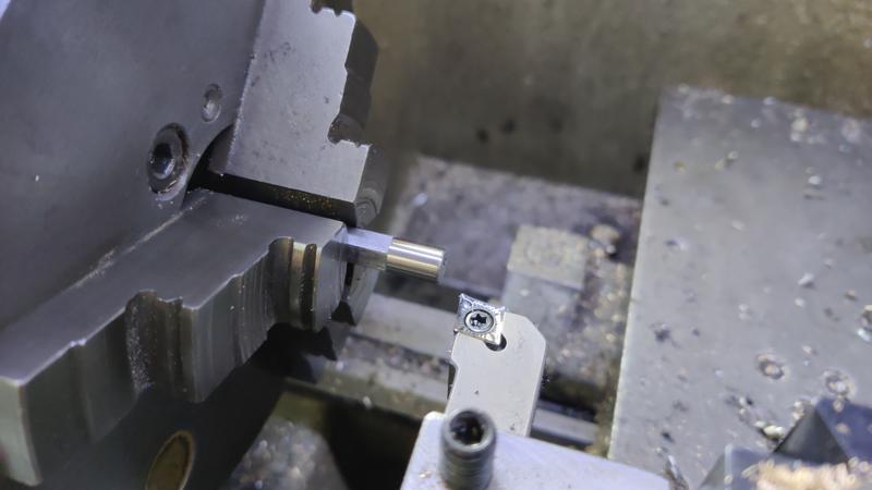
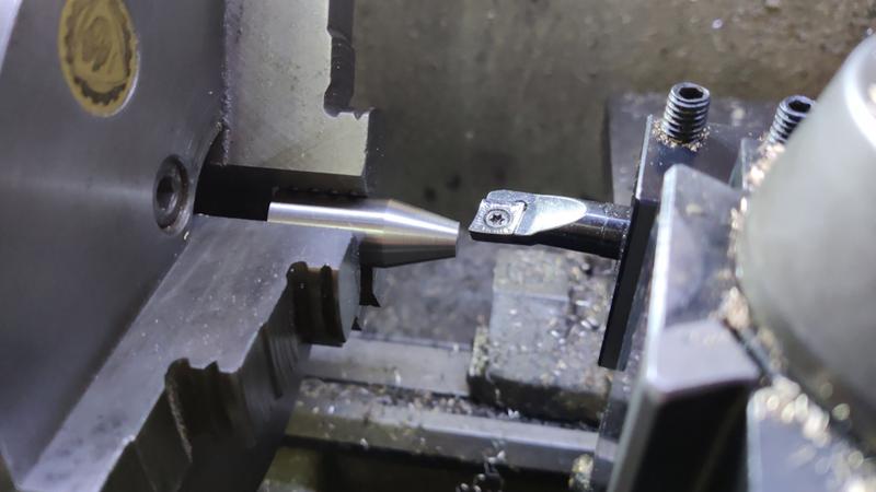
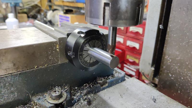
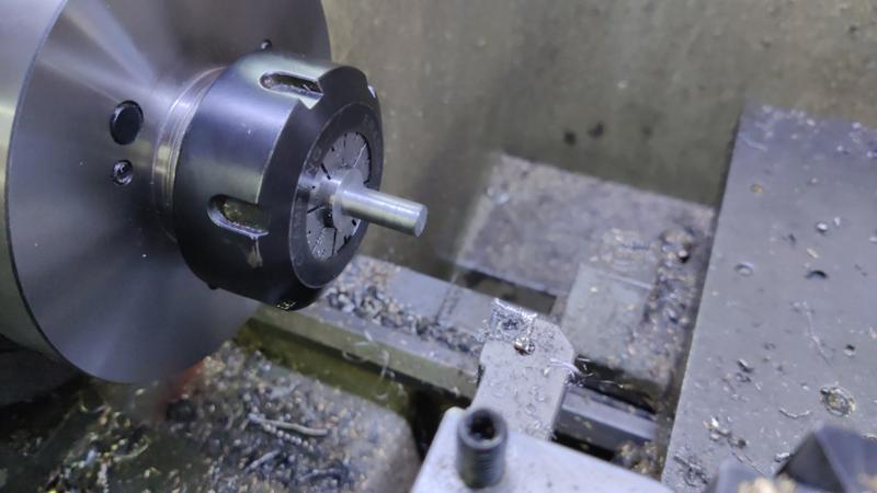
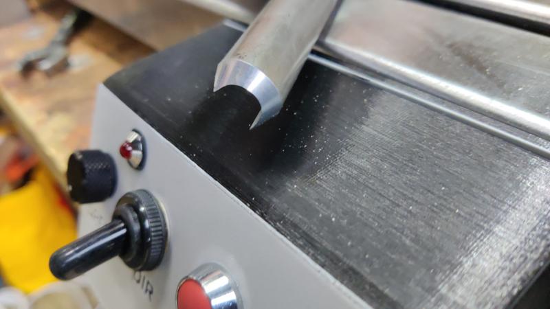
There's still a couple of holes in that lid, which sawdust could get into, so I mounted a bit of 20 mm
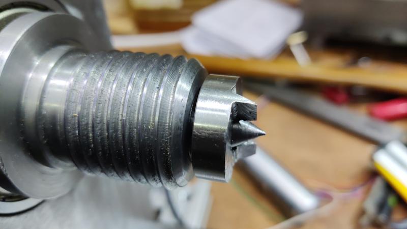
303 stainless bar in the four-jaw chuck, rather dramatically shoved off-centre. I then faced it and turned it down to 4 mm:
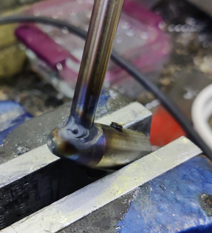
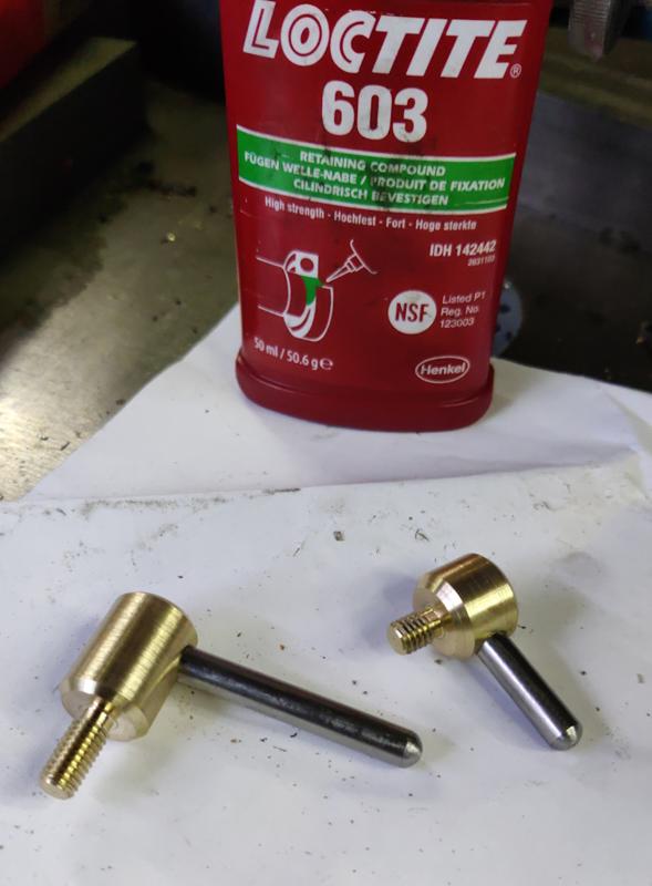
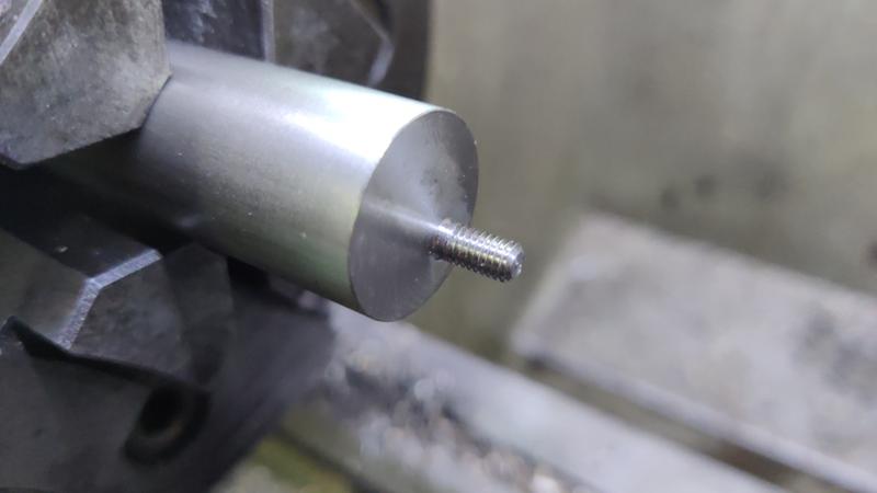
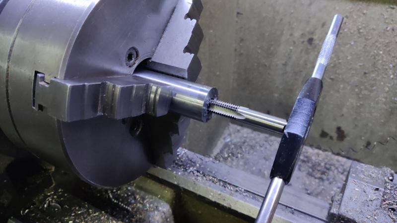
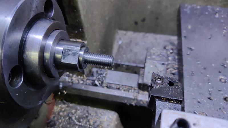
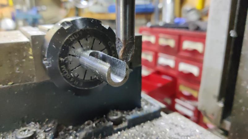
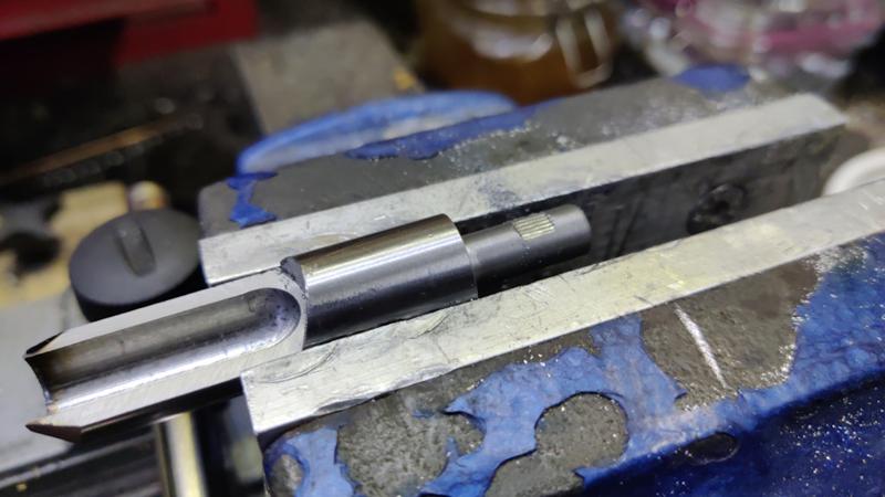
I used a die to cut an M4 thread on the reduced diameter bit:
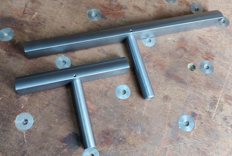
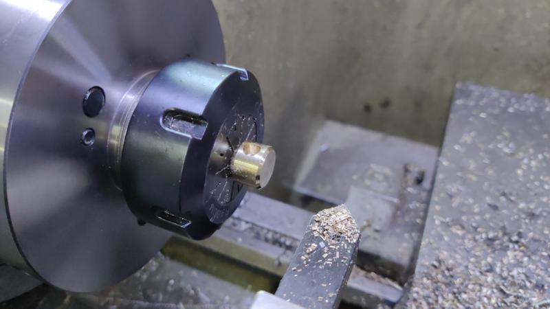
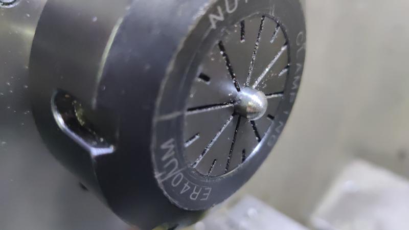
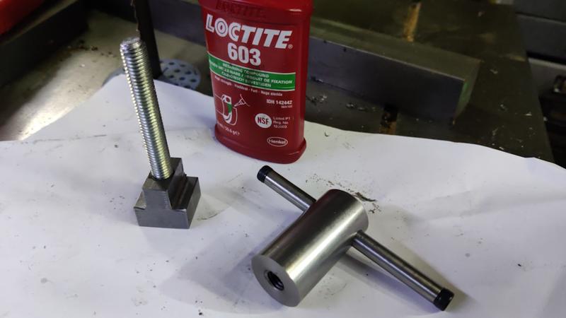
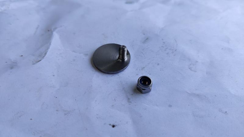
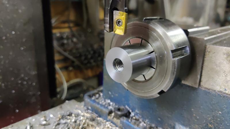
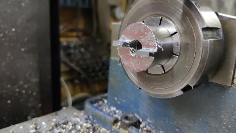
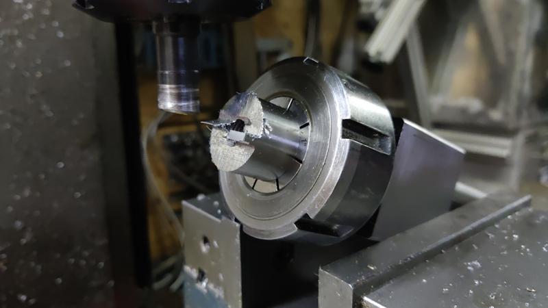
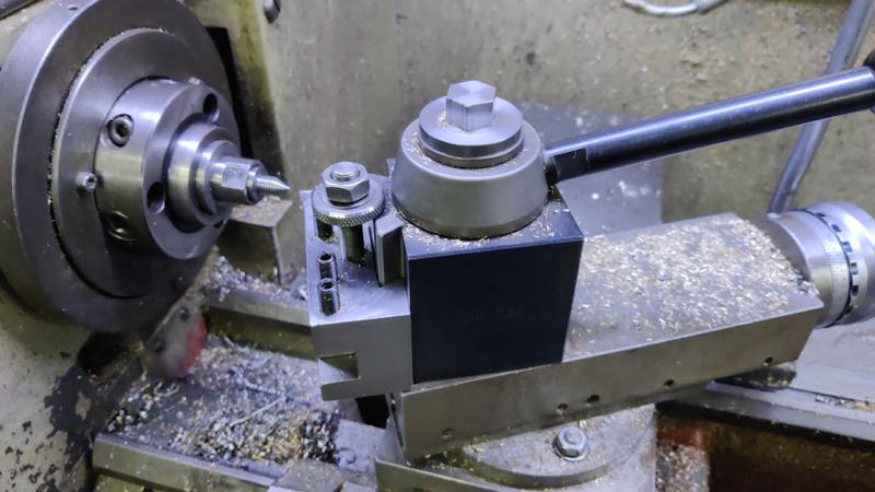
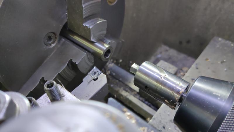
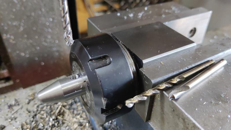
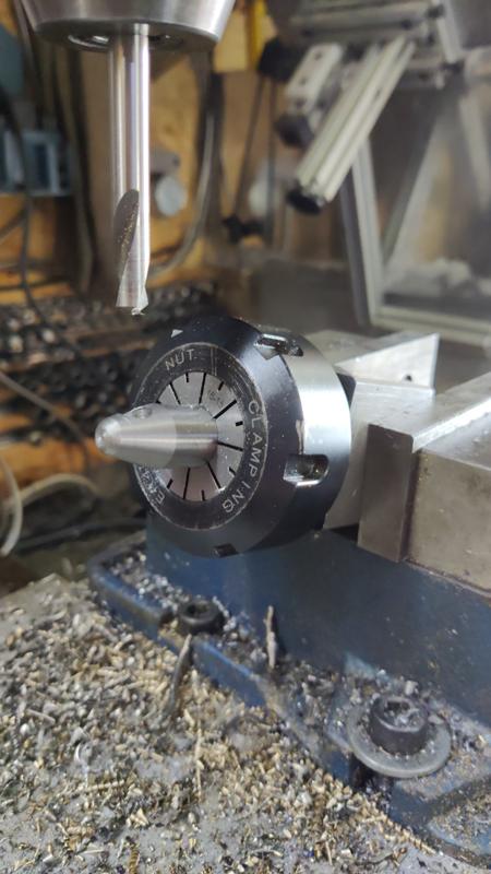
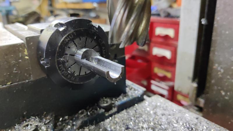
After cutting off with the bandsaw, I then used my home-made soft-jaws to hold the part the other way round to tidy up the cut-off face:
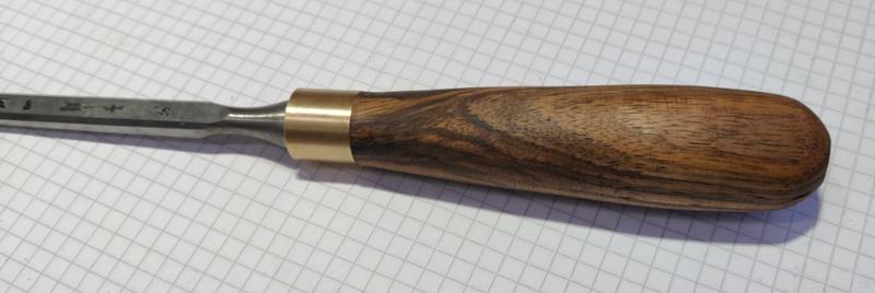
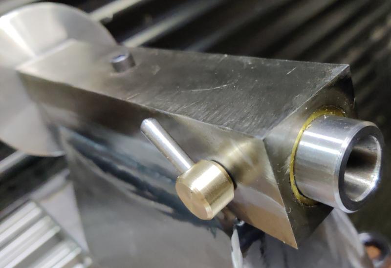
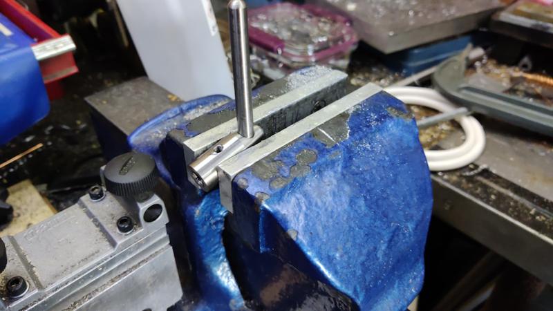
The finished part, along with the nyloc nut that will hold it in place:
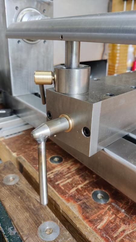
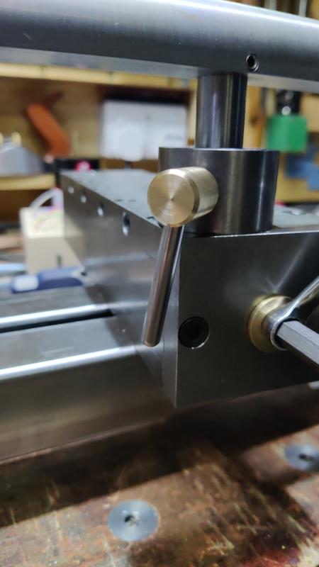
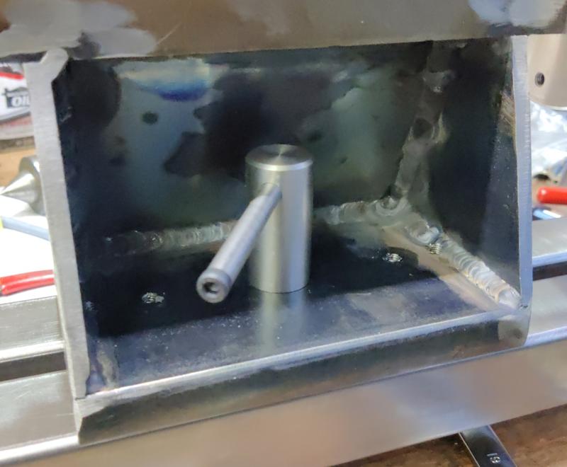
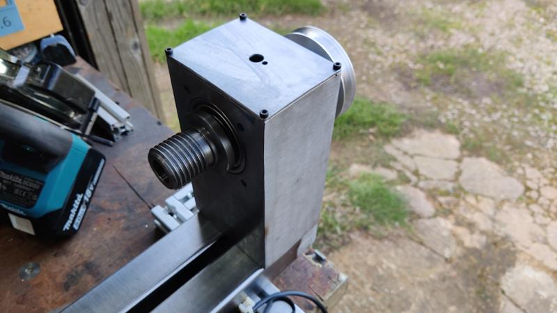
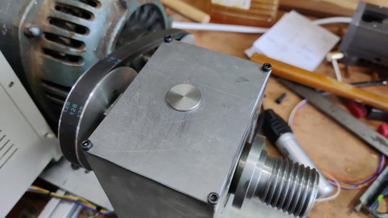
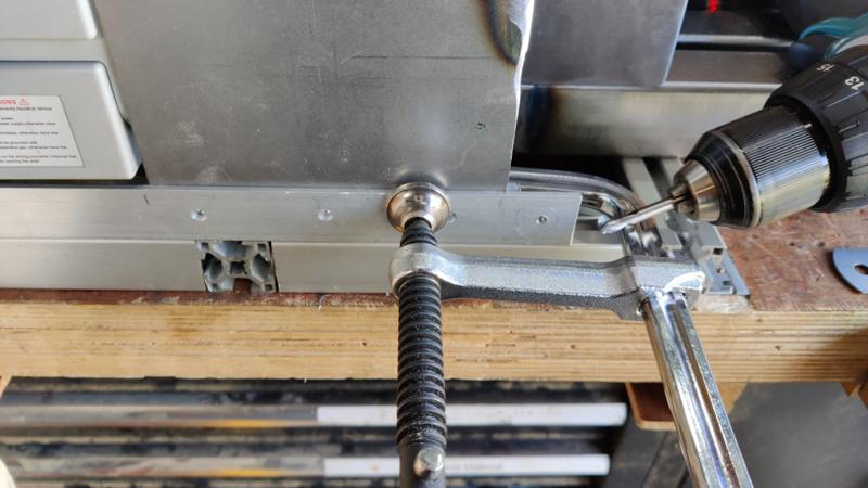
This is what it looks like in situ:
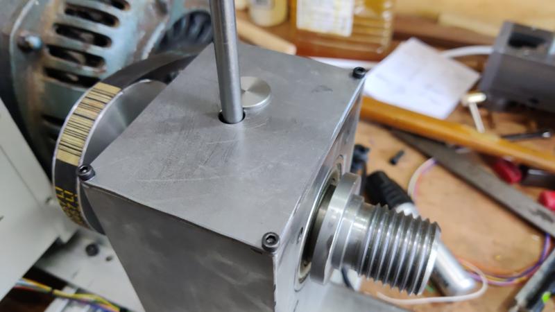
It can be rotated out the way to allow tommy bar access:


")
 bscene-drinkingcheers:
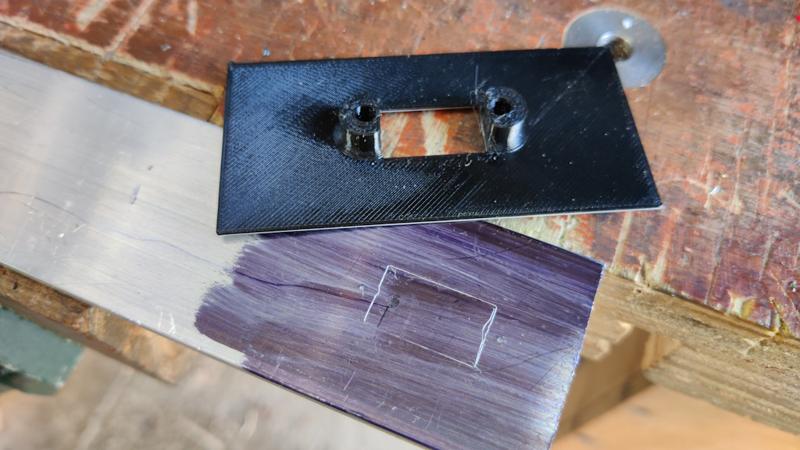

") :
:

")