• Hi all and welcome to TheWoodHaven2 brought into the 21st Century, kicking and screaming! We all have Alasdair to thank for the vast bulk of the heavy lifting to get us here, no more so than me because he's taken away a huge burden of responsibility from my shoulders and brought us to this new shiny home, with all your previous content (hopefully) still intact! Please peruse and feed back. There is still plenty to do, like changing the colour scheme, adding the banner graphic, tweaking the odd setting here and there so I have added a new thread in the 'Technical Issues, Bugs and Feature Requests' forum for you to add any issues you find, any missing settings or just anything you'd like to see added/removed from the feature set that Xenforo offers. We will get to everything over the coming weeks so please be patient, but add anything at all to the thread I mention above and we promise to get to them over the next few days/weeks/months. In the meantime, please enjoy!

Mike's ext'n & renovation (solar panels)

Oh, That saying about beauty and joy...
A thing of beauty is a joy to behold forever, but here the things of beautiness will be joyful to the beholder for a very long time.
Glue-ups, cock-ups and set-ups will soon be forgotten..

My old woodwork teacher, Mr Higgo, would have given you 110% for your projects!
 
mjdewet":2561r7hb said:
Oh, That saying about beauty and joy...
A thing of beauty is a joy to behold forever, but here the things of beautiness will be joyful to the beholder for a very long time.
Glue-ups, cock-ups and set-ups will soon be forgotten..

My old woodwork teacher, Mr Higgo, would have given you 110% for your projects!

Most Teachers are lost to time, but the best ones are always remembered, actually there were some dreadful ones I wish I could forget and wish I’d never come across as well.
 
mjdewet":1648td0p said:
.....My old woodwork teacher, Mr Higgo, would have given you 110% for your projects!

Thanks Thys. Good to see you here.
 
Attention turned to drawers. First, drawers fronts. This was a good opportunity to use up a heap of off-cuts. In the process of cutting bits up for the purpose, I developed a theory about cock beads. I've pulled it out of thin air with no reference to any historic literature or to anybody who knows anything about the subject, so treat it with a pinch of salt. I'll start with that, then bore you to tears with a long-winded drawer post.

Boards over say 7 or 8 inches wide I tend to cut to length with a hand saw on the saw horses, rather than with a tenon saw on bench hooks, which takes twice as long and costs twice as much energy. A panel saw produces a rough under-edge:


0RVpWC0.png

r5ylhPM.png

You then have the option of planing away enough of the surface to get rid of it (more energy and time), or you rebate the end and stick on a cock bead.

That's it. That's my theory: cock beads are as much about cleaning up a fluffy sawn edge as they are about the aesthetics of the finished piece.

Using up scrap takes a bit of thinking-time and chalk:

hOnFRyf.png

DnrVxCn.png

Right, having roughed out the fronts, I needed to make a heap of beads. My first instinct these days is to look for a suitable hand-tool, and I found a nice beading plane in amongst some woodies I picked up recently:

J4NPlko.png

With a few minutes of rubbing with a thinned linseed oil it looked a bit better. It took seconds to sharpen and set up:

zZ4ATjU.png

I cut out heaps of strips and thicknessed them in the PT, before putting one good face and edge on them with a hand plane. I found this set-up worked quite nicely when edge planing strips which were only 7mm thick:

95STHvg.png

I found chalking the edge helped tell me when I'd got to depth with the beading plane:

EBnUwaG.png

......and I soon had a heap of beads:

w5ecfNd.png

You'll notice 2 different widths. More on that later.

Then, lots of chopping out dovetails by hand. As is my wont, I marked no angles, and used no guide....because angles aren't important:


h91hUGV.png

EnzEVjh.png

The critical, critical step in drawer making ios to make the fronts with their top-bead fit exactly in their allotted place (parcel tape has zero thickness, remember :) ):

OlHCsCl.png

With the desk being in the house, 30 or 40 metres from my workshop, I got my 40 year old Workmate out to do the fine adjustment on site, as it were:

AR632PX.png

Here are the drawer fronts after the rebate for the cock beads has been cut (on the router table, I'm afraid. I don't have a knicker on a rebate plane that I can trust):

UoVOwuM.png

I had a very good reason for cutting the rebates before assembling the drawers, but for the life of me I can't remember it now. It happens more often these days......

Notice that this rebate runs along the long under-edge of the drawer fronts, which may not be entirely orthodox. This gives one the opportunity of making the rebate half a hair taller than it woiuld be to bring everything flush, so that the spacing under the drawers is built in without planing the cock bead.

A typical rear corner joint (ply drawer bottoms, so the backs of the drawers are the same height as the sides.....which of course was to cause additional work later):

vVEovxW.png

I dry fitted all the drawers to make sure the fit was OK, and here is one with the top bead held loosely in place so you can see the general idea of how these beads work:

yqjo86P.png

Continuing on the theme of incredible faffing about, and doing things seemingly out of order, next I rough-cut the stopped mitres on the top bead strips:

r5cJVPj.png

They would be pared in situ. I had to do things in this order because the drawer front is stained, and I couldn't risk getting that anywhere near the pine of the drawer sides. This meant the fronts had to be stained before the glue-up. So, all the top strips were glued in place:

BBlRj1q.png

When they had all been stained, (and I did the loose beads too at the same time), I glued up the drawers:


h5x8Gir.png

2rC2VLj.png

Another critical step comes next, which is offering the drawers into place and tweaking the fit. But you've got all the references edges perfectly aligned and everything bob-on square, so there's no adjustment necessary, right?

Applying the beads was easier than planing the beads to the right width (depth, really). Paring the corner of the top bead was the hardest part:

voEQe5D.png

You start with this:

qqmmjCL.png

.....and just plane.....offer up.......plane........offer up...... until they fit:

(this is where I'd post the "after" photo if I'd remembered to take it).

Anyway, here are the glued-up beads drying:

IqoNZqv.png

TCZonaU.png

Tape and thinned oil/ varnish mix, times 3 coats:

QMRESyj.png

It's a good idea not to leave them out on the patio table drying in the sun when the heavens are about to open. Tipping water out of nearly finished drawers would be so disappointing, wouldn't it.....

J13XMbJ.png

Hammering pins in for the drawer stops in a 70mm opening turned into something of a saga, as you might imagine. Leave it to me.......I'll make all the mistakes for you. Anyway, they're in:


jkDYm8B.png

kaJqHdL.png

OT8QCLn.png

Jp1TLHv.png

MftHi2X.png

That's all the orthodox drawers. The rest have planted-on fronts so should be a bit easier, but they'll have to wait. I've more important things to do.
 
Tricky getting those beads on correctly Mike, I’ve never tried to get that effect, and therefore haven’t thought about it, it probably is, but is that the way it’s always been done? Can’t think of an easier way except for screwing on a false front which wouldn’t look very good I’m sure.
Ian
 
Turns out (I read about it afterwards) that the traditional way is to have a full depth applied bead at the bottom as well as the top, and just have the narrow beads on the sides. I was working it out for myself, and didn't consider that option. The thing is, that would mean having three loose pieces of wood you would have to keep together when doing the fitting into the opening, so something of a fiddle.

Goodness knows how they held things together temporarily in the days of yore, before the invention of (zero-thickness :) ) parcel tape.
 
Nice work. Did they not use headless pins in the past? I've seen work done on an antique walnut cabinet where it looked as if beads had been pinned on with fine nails with the heads snipped off. English I think.
 
Great work, as ever, with your own original twist to it.

Fwiw, I think cock beading was generally much finer, with the bead itself only being about 1/8" diameter. Yours look bigger, a bit reminiscent of a beaded door panel. I'm not saying that's a bad thing, it makes a distinctive, original piece rather than a repro antique.

But I don't buy your suggestion about cock beading being a way to avoid a ragged sawn edge. It was normal practice to shoot the ends of drawer fronts to fit the openings, which would remove any raggedness with much less effort.
 
Mine is about 5mm in diameter (3/16ths)......but yes, I agree. The fine bead I put on the edge of the uprights would have looked better. I was rather restricted by the tools I had, given that a scratch-stock couldn't work on such small pieces of wood.
 
Mike G":3kll6yst said:
I was rather restricted by the tools I had, given that a scratch-stock couldn't work on such small pieces of wood.

Mike, Mike. So near but yet so far! It's been a pleasure to watch you move away from your old minimum toolkit approach as you have explored more interesting byways of woodworking (carving, older styles of planes etc) but if you had started off this project by saying that you lacked a small beading plane I'm sure you would have been helped out very readily! Next time...
 
AndyT":1k14d4sd said:
Great work, as ever, with your own original twist to it.

Fwiw, I think cock beading was generally much finer, with the bead itself only being about 1/8" diameter. Yours look bigger, a bit reminiscent of a beaded door panel. I'm not saying that's a bad thing, it makes a distinctive, original piece rather than a repro antique.

But I don't buy your suggestion about cock beading being a way to avoid a ragged sawn edge. It was normal practice to shoot the ends of drawer fronts to fit the openings, which would remove any raggedness with much less effort.
I'd agree on all points, but you don't need a scratch stock to round over the edge of a bit of wood 3mm thick. A couple of passes with a block plane along the edge and then some work with sandpaper and a cork block would produce a very acceptable bead profile; it's exactly the same technique I use to round over the back of any drawer(s) that I make:

IMG_1084.jpeg

The drawer sides here in Brown Oak are only 5mm thick - Rob
 
A round over isn't a bead, though. You can't do a quirk with a block plane.
 
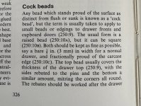
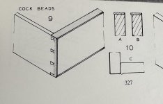
Mike, from Joyce's 'TToFM, original edition, p 326/7:

IMG_1088 2.jpeg

IMG_1087.jpeg

No quirks, nothing fancy. 3mm thick, simply rounded over and easily done with a block plane. Here endeth the lesson :lol: - Rob
 
It's been a very long time since I posted any work, but I have been plodding on. I've pretty much been restricted to weekends, so this has been slow going. Last December I left the oak frame of my sunroom looking a little like this:

5AjLXLk.png

I then had a hip operation, and whilst awaiting the surgeon's go-ahead to lift heavy weights again, worked on my office furniture. A couple of months ago I was able to resume work on the sunroom. Here's the first joint I made in oak for a very long time:

KJ19XTC.png

There's a big mortice & tenon in there.

This green oak has been stored for 6 or 8 months, and being unrestrained by joints it has moved and twisted. The plates, being no longer straight, gave me a few issues. I had to mark out all the shoulders of the tenons on the intermediate posts very carefully, including making allowances for out-of-squareness of the plates:

Q6C9435.png

Much of the framing involving the roof was marked out using templates. If I could go back to this exact moment, I would re-measure, and get it right this time:

XBE3wab.png

The "after" photo. On the left is the rafter, jointed into wall plate and the vertical which will be fixed to the house wall:

FOriHYW.png

kCJBx25.png

Time hadn't been kind to the wall plate on the southerly gable. It had twisted a mile. The piece of 6x2 clamped to it shows how far out of square it was now:

X5ZEvh5.png

And this was the head of one of the posts. My joints normally fit a bit better than this:

pV5JHx0.png

The problem is that I'd had very little notice of my operation date, so had erected the frame but without putting in more than 2 or 3 pegs. Don't ever make that mistake! I managed to haul the twist out of the plate with a ratchet strap:

hxIeJTb.png

I secured the re-shaped plate with a big piece of threaded rod, and that enabled me to get the pegs into the mortice & tenons, and things started to look a little better:

FgF0FRl.png

I partially erected the newly finished frame myself:

NaFMGWR.png

...and then a friend fortuitously dropped in, and I roped him in to help with the bigger pieces:

0gADULT.png

That all looks quite convincing, doesn't it. Unfortunately, the two rafters aren't parallel. The new one was 40mm higher at the apex than the southern one. The joint on the new one, however, was absolutely spot on:

Gs9xmfw.png

Next time, I move on to the "porch" (it isn't ) framing.
 
I’ll try again – Internet Grrrr.
Well you’re obviously up and about Mike. It’s a real pain what’s happened, that 40 mil is going to drive you nuts forever more and I suspect the only way to fix it is to take down that right-hand top frame, it’s just so obvious against the line of the first floor windows.
As ever a pleasure and an education to watch.
Ian
 
I made a couple more posts, and a pair of very short plates. These carry the projecting roof over the entrance doors:

iCBbGnL.png

E7A0QnA.png

That's a dry fit, for marking-up purposes. Having them in place enabled me to measure for the gable rafters, which are in oak. Tradtionally these were joined with a half lap and nails, or a bridle. I cut a bridle. Now, I reckon the bridle joint is the woodworking joint which requires the most accuracy, so I cut this really big joint with a tenon saw:

qB5i0LE.png

Obviously that wouldn't go full depth, so I finished off with a bow saw and shoulder plane:

gATt09F.png

7vpA2MN.png

That carriagemakers shoulder plane is an absolute game changer when green oak framing, in my view.

The female side of the joint:

kAjWRRq.png

IdLZaLd.png

595Z3v5.png

And the completed pieces:

TuW2X21.png

I put it in place, temporarily:

E2pxHGC.png

XvW5Z9v.png

I cut the lintel and did a shallow lap joint:

7diEobH.png

That lot had to all come out of the way, then, to allow me to make and fit the two central oak rafters.

Now, these rafters will weigh 120kg or more. There is no way of offering them up to mark-up. It had to be done with a template. 3mm MDF is a bit floppy, so I stiffened it up with some battens, cut the plumb cut at the top, and pinned it temporarily in place to take measurements and mark it up:

DJTpGJK.png

Those marks are then transferred to the rafter:

Lkyk42d.png

kdFRHnV.png

There is no plate at the house wall onto which this big pair of oak rafters will sit. I came up with a bracket/ knee to do the job instead:

kFWgilb.png

qyWpq83.png

These would be supported on a plate bolted to the wall. I cut out some of the render to allow me to fix directly onto the wall structure:

Tv0ricL.png

I then offered up the top bracket and checked it with my template:

cudrSK0.png

You'll note that I had already put some softwood rafters in place, sitting on a plate bolted to the wall.

I also need a knee at the bottom. This big rafter comes in at an awkward 3 way junction (post, plate, rafter), so I couldn't cut a big enough joint to take the bottom end alone. It needed some help, so I made a knee:

Rdgjbsf.png

That was easy in the workshop, on the bandsaw, but still involved a fair amount of hand-tool work:

Sa1LO0d.png

I thought I would use this excellent carriagemakers plane thingy (help, AndyT. I know, you've told me already what it's called, but I've forgotten!) to clean up the curve:

RSudCsg.png

But it chattered uncontrollably:

pTwL2LP.png

I fiddled about with it for a long time, before abandoning it in favour of an orthodox spokeshave.

Next, fitting it to the post:

ViddzR2.png

8mKtSC3.png

Chiselling horizontally is hard work, and this required 2 accurate mortices:

6DFvpm0.png

I then house-out so that when the timber shrinks I still have a neat joint you can't see through:

xoQ5ERx.png

TG1LVQ5.png

With the top bracket in place to hold the other end, I could then offer up the template, again, to accurately mark out the shoulder location on the bottom bracket:

suXQVxr.png

Which I duly cut:

vORsxfN.png

And checked against the template, again:

saBPvOW.png

Having completed the knee, I then housed out for it on the underside of the rafter:

otrCN67.png

CDZtYac.png

Finally, I chopped out a (crude!) socket in the top plate, to share the load of the rafter with the knee:

bMCiAeY.png

I repeated the work for the other rafter of the pair, then rang foir help lifting them into place. Remember, these rafters have never been trial-fitted. I was relying 100% on the accuracy of my templates. One dropped in perfectly first time, and the other required adjusting in-situ at the plumb cut (the easiest thing to get right I got slightly wrong!):

NBBBpA0.png

w2z2u4e.png

FLUoYwF.png

More templating followed, as I need to organise the juinction between the "porch" plates and the rafters I'd just put in place:

xplKLte.png

I haven't got a photo of that junction, and it's too late now as the roof valleys hide it. Anyway, that's the oak work finished, probably a year after I started it! Next, making the roof.
 
Echo the above, great to see you are fully fit again.

With autumn/winter rapidly approaching will you be able to glaze all that before the really wet weather arrives? Or, I suspect, that a little weathering bothers you less than it would me.
 
The roof should be done within a week or two, (felt and battens this weekend), and I'll also be doing the glazing of the fixed windows in the next few weeks. However, the openable windows (2 of them) and the doors are not going to be done in time for winter, so there will be plastic over those window openings, and maybe a piece of polycarboate put in as a temporary door. I will then be cleaning the inside of the frame with oxalic acid.
 
3rd attempt bl....... internet.
My reply crossed with your big post Mike, well you’re obviously up and at em Mike, what will you do about the 40mm as it will show up badly under the first floor windows, a long wedge piece on the left? But wouldn’t it be visible?
Btw you’re making me feel tired! ( and useless and a fraud but that’s my problem lol )
 
Cabinetman":sqx7y3nb said:
3rd attempt bl....... internet.
My reply crossed with your big post Mike, well you’re obviously up and at em Mike, what will you do about the 40mm as it will show up badly under the first floor windows, a long wedge piece on the left? But wouldn’t it be visible?

It's sorted already, The oak rafters are 95mm below the level of the top of the softwood rafters, (other than the wrong-'un). I have put a 4x2 on top of the others, and a long wedge-shaped ex 4x2 on top of the dodgy rafter. This will be hidden behind a barge board externally, and I'll plant a piece of oak trim over the discrepancy internally. Lucky, that gable isn't going to be glazed, but boarded externally and plastered internally.
 
On the back of the pair of rafters over the door is a little mortice, just to properly locate the end of the ridge beam. I prepared the ridge:

uN0X7kr.png

This roof is complicated by the fact that I don't want a flat ceiling over the entrance area, so it will have what are called valley rafters. In other words, the little projecting roof isn't built on top of the main roof, (on lay boards), but meets it a little like an upside-down hip junction. It's further complicated by the fact that both rooves are at very different pitches (22.5 degrees and 35 degrees). This made it impossible for me to calculate any of the junction angles, and I had to work them out physically.

I decided to trim the big opening at the junction of the ridge beam with the main roof:

fmEzHIG.png

Kag5QKO.png

Working out the compound angles of the valley rafters was fun. After working out the exact point at which the planes of the two rooves met, I fixed a line. Then, I cut scraps at either end, and by a process of repeated offering-up-and-adjusting, I got all the angles sorted:

NlluIZr.png

The trimmer complicated matters in some ways, and this is the top end of the valley rafter that resulted:

HTQoA5w.png

Having worked out both ends on scrap you just pin them in place and measure between them to get your valley rafter length, and it worked:

cIkJUUG.png

Then it was just a question of infilling with jack rafters (note the 4x2s sitting on top of the oak rafters):

oOLUsnR.png

TeV2Pmj.png

mUa4F31.png

Look closely at this photo and you can see the oak gable rafter out of line with the rest of the roof:

6lijHLS.png

It was an easy fix, and I'll grab some more photos tomorrow.

-

Those of you saying I'm working fast have missed the fact that these photos from the last 2 or 3 days cover probably 2 months or more. It has felt like an almighty plod.
 
Yeah, that's been the major complication of the whole roof. Where does the gutter go when it intersects the valley with another roof below at a lower level? I've moved a pair of rafters since these photos, and it's all looking a lot easier now.
 
SamQ aka Ah! Q!":2jdue0i4 said:
That carriagemaker's shoulder plane is an absolute game changer when green oak framing, in my view.

SO good to see it fulfilling a need. :text-bravo:

Yep, it's brilliant. Much appreciated, Sam. When I get a moment I'll put some finish on the handle, but otherwise, it's absolutely spot-on.
 
fiveeyes":2gehbgur said:
good to see that your health has allowed your return...do take care

It's more been my work load. I've been fit enough to do this work since about March/ April, but I've had a huge work project which has tied up every hour god sends for about 5 months.
 
Here's that tapering end rafter I mentioned, to cope with the out-of-line oak rafter:

3XcDDD2.png

The next job was to infill between the rafter in the valleys, in preparation for taking the lead. I also trimmed for the Velux rooflight, and inserted the short rafters top and bottom:

vE6tebf.png

I moved a p[air of rafter on the "porch" roof when I realised where the valley would finish, and it made the whole thing make a lot more sense. It's complicated when two rooves at different pitches and different level meet!

CSZKwzk.png

I used 195 x 45 timber for those valley inserts, other than at the eaves where I don't have the depth of rafter to accomodate them. There is rebated for some ply:

vEWjJAO.png

I ripped up some scrap to make eaves closers, and nailed them in place between the rafter feet:

KBspJv1.png

KBspJv1.png

Now, the bottom of the valley makes a lot more sense:

by2e6AD.png

That was the morning accounted for. On to the next phase: felt & battens (felt being breathable membrane, not felt...but, you know.....). First step is to fix on the eaves carrier (AKA eaves protection):

J6gHIp8.png

The width is completely unnecessary, but selling us over-wide sheets is I guess the only way felt roofing manufacturers can stay in business these days. The rest of Saturday and some of Sunday was then just a question of measuring, cutting, stapling, and nailing on battens:

lROpixq.png

pgALhW5.png

I6LYkdG.png

The north gable, as I said, is going to be boarded rather than glazed, so I did the studwork, and put the membrane and battens in place:

GhmzZtX.png

4YOLK0u.png
 
This has come on leaps and bounds since I last looked, but its looking great. Whats going on the roof, batten spacing looks too wide for plain clays. Whats the roof pitch?

Mark
 
Back
Top