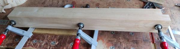
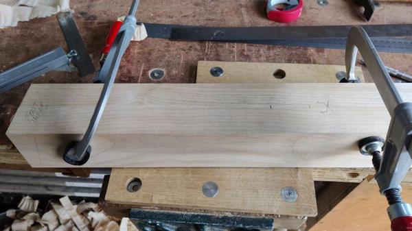
• Hi all and welcome to TheWoodHaven2 brought into the 21st Century, kicking and screaming! We all have Alasdair to thank for the vast bulk of the heavy lifting to get us here, no more so than me because he's taken away a huge burden of responsibility from my shoulders and brought us to this new shiny home, with all your previous content (hopefully) still intact! Please peruse and feed back. There is still plenty to do, like changing the colour scheme, adding the banner graphic, tweaking the odd setting here and there so I have added a new thread in the 'Technical Issues, Bugs and Feature Requests' forum for you to add any issues you find, any missing settings or just anything you'd like to see added/removed from the feature set that Xenforo offers. We will get to everything over the coming weeks so please be patient, but add anything at all to the thread I mention above and we promise to get to them over the next few days/weeks/months. In the meantime, please enjoy!

Mini-Moravian

Supposin’ you screw the board to the sled? Obviously the heads would need to be well countersunk and you would need to sacrifice some timber after screws were removed. I was wondering if a much larger version of the one I made for squaring a small log on the band saw might work where I screwed into the ends which are then cut off.

Yes, I suppose I could now you mention it. Some of the boards are only just long enough so it wouldn't have been viable, but there are definitely some that would have worked like that. I think I'd still need the wedges (and some means of holding them in place, but perhaps tape would do). Of course I'd still need a longer sled than I have.

Anyway, the exercise probably did me good!
 
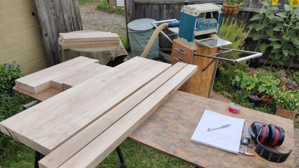
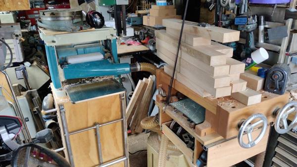
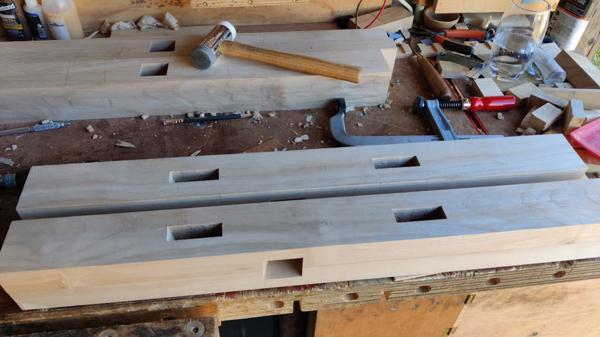
Once I'd cooled down enough to carry on, it was time to get the thicknesser out. For anything but the shortest boards, there isn't space in the workshop for that, so the first thing to do was wheel the trolley (with wings!) out into the garden (with a little bit of assistance from Carolyn as it's flipping heavy - I can do it on my own but it gets a bit precarious at times). I could then feed all the boards through with the planed face down, then when the upper face was clean, flip them over and plane until the hand-planed face was fully smooth (or at least as smooth as a thicknesser will manage).

That all went mostly very well, except that I stupidly put one of the leg halves through the wrong way up on the first go, so the face I'd hand-planed got thicknessed parallel with the wonky face. That one had to go back into the garage to be hand-planed again and then I carefully marked all the reference faces of all the boards to make sure I didn't do it again!

I did the boards in batches (legs first, then cross-pieces, then stretchers, then top pieces). That way I could take the minimum amount of wood of each "set" while making sure all the pieces in a set were the same thickness.

It really didn't take long until they were all done:

2025-07-05-16-thicknesser-set-up-and-all-thicknessed_600.jpg


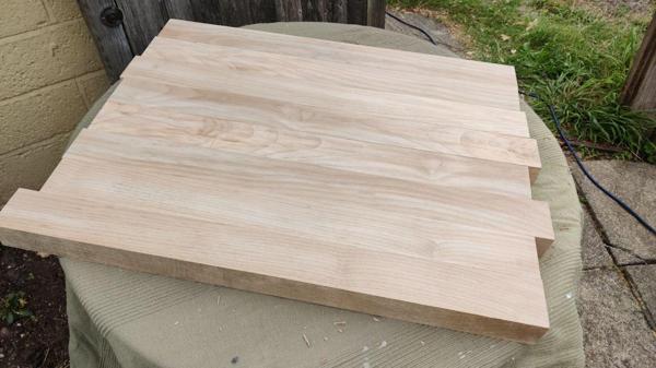
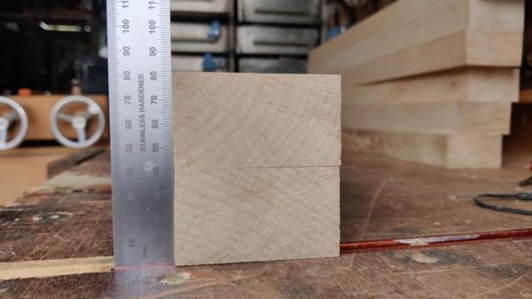
Close-up of the pile of leg halves.

2025-07-05-17-legs-close-up_600.jpg


Once that was all done, I measured all the pieces:

  • Top pieces: 48 × 170 × 1220 mm
  • Stretchers: 40 × 80 × 1400 mm
  • Leg halves: 47 × 70 × 720 mm
  • Upper cross-pieces: 47 × 90 × 400 mm
  • Lower cross-pieces: 47 × 90 × 590 mm

I'm sure most people reading this won't be interested in those dimensions, but it seemed sensible to write them into this post in case I lose the piece of paper they're written on!

The next job will be to throw those dimensions at the CAD model and see what they look like. It seems likely that some of the pieces will need to go through the thicknesser again once I've decided what size I want them to be, but we'll see. Eventually everything will also get hand planed again to get rid of the machine marks, but not until the size is finalised.

I'm really pleased to have got this far today. I thought it would take me a lot longer to get the first faces planed and to be ready for the thicknesser. Depending on how long the CAD playing takes tomorrow, I might get them re-thicknessed and then next weekend I can start thinking about edge-planing and perhaps even starting the joinery (although if the weather forecast stays as it is at the moment, it might be too hot to do anything at all next weekend).
 
Not sure why you didn’t just put your long ruler onto the edge of the board and draw a line along it?
Your putting a bit of leather under to prevent the weight of the planing action deflecting the board reminded me of a naughty trick from when I hand planed a lot of tabletops. That small area that the plane couldn’t reach without a whole lot of planing of the rest of the top can be reached by adding something like your leather under the top where the low point is, amazingly this deflects the top upwards enough to be able to plane it, and yes you’re correct that then the top isn’t level but it’s a tiny amount and it isn’t at all noticeable.
 
Not sure why you didn’t just put your long ruler onto the edge of the board and draw a line along it?

Mainly that I don't have a long enough (1.4 metres) ruler. I could have done it in two sections I guess but the surface gauge thing is how I would do it as a metalworker (of which I have more experience) so I think it just seemed the most obvious way to me.

Your putting a bit of leather under to prevent the weight of the planing action deflecting the board reminded me of a naughty trick from when I hand planed a lot of tabletops. That small area that the plane couldn’t reach without a whole lot of planing of the rest of the top can be reached by adding something like your leather under the top where the low point is, amazingly this deflects the top upwards enough to be able to plane it, and yes you’re correct that then the top isn’t level but it’s a tiny amount and it isn’t at all noticeable.
(y)
 
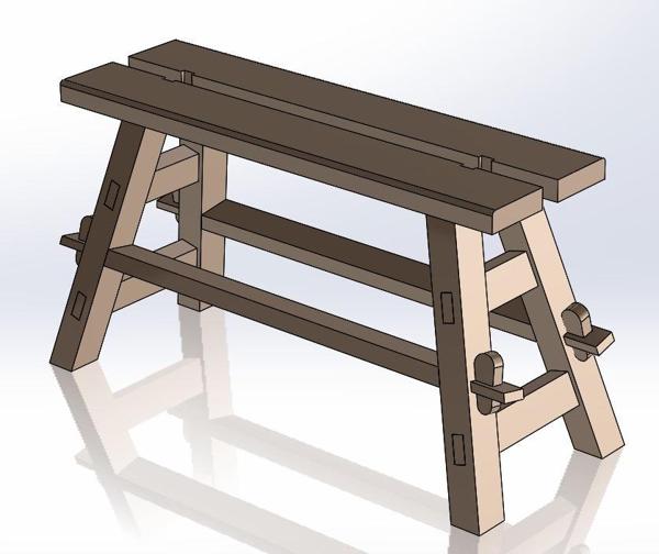
I've been playing around in CAD this morning and I think I'm most of the way there with part dimensions. Most of it is quite straightforward really.

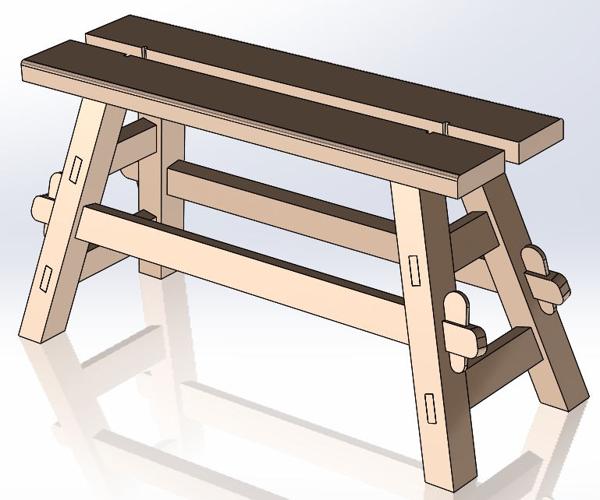
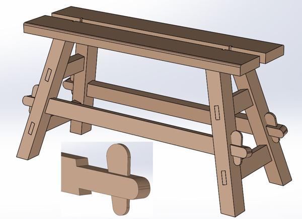
This is what the model looks like at the moment:

2025-07-06-cad-01-updated-model-with-wood-dimensions_600.jpg


I've made the legs 80 × 70 mm. The maximum size I could get out of the pieces I prepared yesterday would be 94 × 70 mm, but that looked a bit excessive to me, so I'll bring the leg halves down to about 40 mm before they get joined together. The top pieces will stay full thickness (48 mm) as there's no good reason I can see to thin them out further. I'll probably drop the short cross pieces down to 40 mm when I do the legs (although the model still shows them as 47 mm).

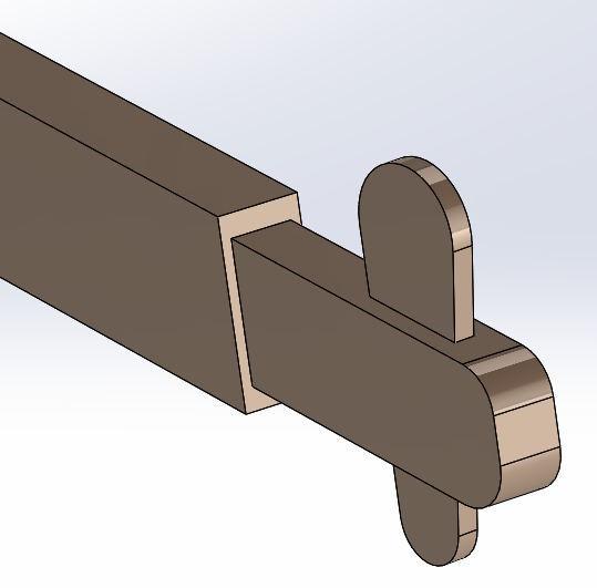
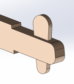
The only things I'm a bit concerned about (and was expecting to be concerned about) are the stretchers. The thickness of the stretchers (40 mm) is less than I'd hoped (as a result of the bowed plank) and that dimension affects the form of the tenon on the end. This is what I've got at the moment (with the wedge in place):

2025-07-06-cad-02-tenon-in-tenon-close-up_600.jpg


The shoulders (on the longer edge) are 5 mm; I'm not sure I'd want to reduce them much more than that. That leaves 30 mm thickness for the tenon, which I've then divided into three such that the wedge is 10 mm and the cheeks are 10 mm. It looks a bit weedy to my eye and I'm a little concerned about the wedge thickness. However, I'm not really sure what to do about it.

I could rotate the stretchers through 90°, which would allow for a chunky 30 mm wedge, albeit with a fairly thin tenon. However, it looks a bit odd and I'm not really sure it's an improvement:

2025-07-06-cad-03-rotated-stretchers_600.jpg


Any thoughts or opinions are as always welcome...
 
That looks absolutely fine to me. The 5 mm shoulder is good too. If you were to dismantle it a lot and the wedges start to suffer you could make some more on your 3d replicator perhaps.
The second version is a no to my eye!
 
That looks absolutely fine to me. The 5 mm shoulder is good too. If you were to dismantle it a lot and the wedges start to suffer you could make some more on your 3d replicator perhaps.

Thanks Ian, that's really useful. I don't think the wedges will be very hard to make (or re-make) so I'm not too worried about them deteriorating. I'd be more concerned if the mortice-in-tenon started having issues.

It did occur to me that I could get rid of the long shoulder and just rely on the shorter one (which is currently 10 mm but could easily be made bigger). That would make the tenon-in-tenon look like this:

1751792195542.png

It would allow for a thicker (drawn as 15 mm) wedge, but obviously reduces the all-round support of the shoulder.

At the moment, my gut is saying to stick with the 5 mm shoulder as shown in the last post, but I thought I'd share that image as well in case anyone thinks it's a better option.

The second version is a no to my eye!

Thanks. It felt like a good idea in my head but as soon as I drew it in CAD it felt like a no to me too.

Overall the only thing I think I would look and double check is perhaps not enough overhang on the bench top, not far out, couple more inches?

When you talk about the overhang, are you meaning the overall width of the top needs to be bigger? Any particular reason?

One of the ways I expect to use this bench is with the tool chest sitting on top and me sitting on the bench with a leg either side. I'll use it like that when I want to sit down and chisel stuff. If I make the bench too wide, then it'll be a bit uncomfortable stretching my legs out to straddle it.

It's currently drawn as 20 mm wider than the tool chest (so 370 mm total width). That's based on reducing the plank width by about 10 mm from the rough-sawn dimension and having a 50 mm gap in the middle. There's no reason why that gap in the middle couldn't increase: I want it wide enough to give clearance for a saw to run down the middle and bigger is definitely better there. Given that the gap can increase and the planks could be 10 mm bigger than drawn, it would be very easy to make the top wider, but as I said I'm concerned about comfort if I do that.

The main reasons I went for 50 mm are:
  1. It gives some nice sturdy top planks without making the top too wide to be comfortable to sit on with legs either side
  2. It's a convenient dimension for the sizes of the wedges, so I can use the stretcher wedges to drive the top pieces apart in order to release the tapered sliding dovetails.
 
No sorry I was thinking the top needed to be a bit longer.
Re the wear and tear on the mortice for the wedge, that could have metal ( brass would be smart?) or plastic inserts at wear points.
 
No sorry I was thinking the top needed to be a bit longer.

Ah I see. Why?

The length of the top can't be changed (without buying more wood), but I could obviously bring the legs further in (& shorten the stretchers).

Re the wear and tear on the mortice for the wedge, that could have metal ( brass would be smart?) or plastic inserts at wear points.

Ooh, that's a nice idea (y)
 
The why, well it’s difficult to tell from the cad, but the top looks to be the same length as the rails with the wedges in? Can’t really say why I would have the top a couple of inches longer, but just in case? Aesthetics?
And yes the under frame could be shortened slightly if needed.
 
The why, well it’s difficult to tell from the cad, but the top looks to be the same length as the rails with the wedges in? Can’t really say why I would have the top a couple of inches longer, but just in case? Aesthetics?
And yes the under frame could be shortened slightly if needed.

The top's slightly shorter than the stretchers at the moment:

1751799221586.png
 
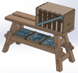
At the risk of spoilers, one of the reasons I've kept the legs as far apart as they are is that I was pondering screwing some little 3D-printed brackets onto the top face of the stretchers. With those in place, it would mean I could do this...

1751801336848.png

... which could be quite handy as long as the brackets hold the drawers relatively securely.

That's the one thing that's stopping me bringing the legs in closer together (and hence having more overhang on the length of the top).

It's not set in stone though. Also, I could still do that, but with the router drawer (which is narrower) being one of the drawers that sit on the shelf:

1751801830585.png

That gives a lot more scope for the stretchers to get shorter (and hence the legs to get closer together).
 
I think that having got this close to a design that would work so sweetly with your tool chest, it would be an eternal source of frustration if you made it so the drawers didn't quite fit.

I expect you will have considered these ideas already, but just in case:

- You could gain a bit more length for the drawers by lowering the horizontal rails a bit.
- You could gain a little bit more space by cutting a rebate along the inside top edge of each rail. (This could also reduce the risk of knocking a drawer onto the floor.)(And you'd have a nice challenge of making a square rebate that's not parallel to the sides of the rail, but I'm sure you'll work out a method to cut that. There are some interesting angles there already!)

And as for the tenon/shoulders/wedge decision, I would go for your second, barefaced tenon option as simpler and stronger.
 
I think that having got this close to a design that would work so sweetly with your tool chest, it would be an eternal source of frustration if you made it so the drawers didn't quite fit.

Yes, I agree!

I expect you will have considered these ideas already, but just in case:

- You could gain a bit more length for the drawers by lowering the horizontal rails a bit.

I definitely thought of that first time round (when I had the original idea of putting the drawers there), but I hadn't considered revisiting it to help get the legs closer in. That's worth having a look at.

- You could gain a little bit more space by cutting a rebate along the inside top edge of each rail. (This could also reduce the risk of knocking a drawer onto the floor.)(And you'd have a nice challenge of making a square rebate that's not parallel to the sides of the rail, but I'm sure you'll work out a method to cut that. There are some interesting angles there already!)

Thankfully most of the angles are single (rather than compound) so it's not as bad as it looks I think. I had originally thought about cutting a rebate, but it felt rather challenging and a 3D-printed bracket sounded a lot easier! I might change my mind and be brave when I get that far, but I'm a long way off at the momente

And as for the tenon/shoulders/wedge decision, I would go for your second, barefaced tenon option as simpler and stronger.

Thanks. It would certainly be a heck of a lot easier so if you think it isn't going to lose too much strength from the lack of side shoulder then I'll go with that.
 
I started the morning (after playing with CAD a bit) by using the thicknesser to bring the legs and the cross pieces down to 40 mm thickness. I did that in the garage, which isn't quite as ergonomic as doing it in the garden, but it does save trying to manoeuvre the thicknesser trolley over some rather rough ground en route to the garden. This is what the set-up looks like in the garage:

2025-07-06-01-rather-cosy-in-the-garage_600.jpg


While thicknessing, I stand on that little bit of clear ground you can see to the right of the thicknesser trolley. I put all the planks on the bandsaw table and then feed them in with one hand, catch them with the other and put them on the portable workbench. It works, but it isn't ideal.

With all those pieces reduced in size, I could stack a couple of leg halves up to get a sense of scale:

2025-07-06-02-getting-a-sense-of-the-leg-size_600.jpg


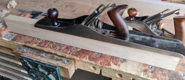
It was then time to deal with the machine marks from the thicknesser. For now, I've just done one face of each board:

2025-07-06-03-planing-leg-face_600.jpg


... and one edge:

2025-07-06-05-edge-planing_600.jpg


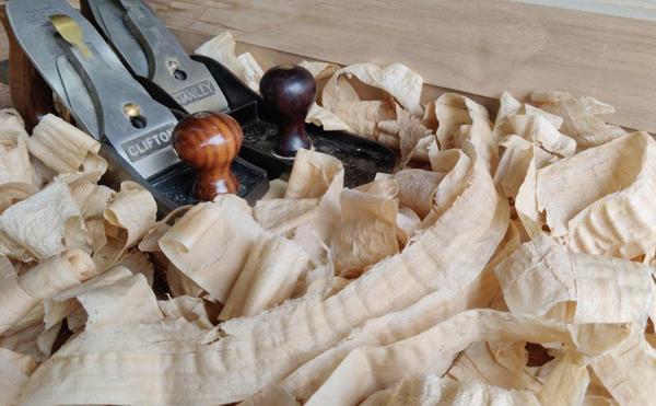
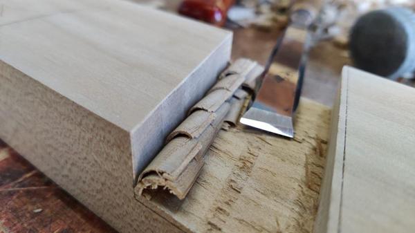
With the heat (and the fact that Sycamore takes a bit more effort to plane than the Sweet Chestnut I've been using recently), I needed to take a bit of a break after each pair of legs, so I used one of those rest periods to get a photo of some plane shavings because, well, why not?

2025-07-06-04-taking-a-break_600.jpg


With all the legs planed on one face (which will become the inside of the leg) and one edge (which will become the inside edge), I could pair them up. I then wanted to get on and do a bit more work on one leg. I've tended to work on a single part when doing something relatively new: do one part as far as I can, then do all the others at the same time. That way I'm less likely to mess all the parts up in one go!

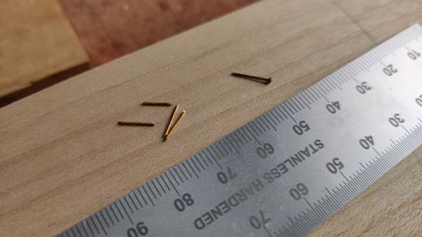
Having decided which one goes with which, I got some small brass pins and chopped the heads off:

2025-07-06-06-nails-with-heads-cut-off_600.jpg


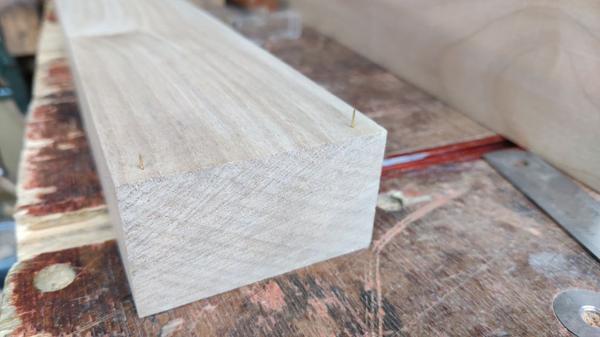
I then tapped two into each end of one of the leg halves (very near the end: the bits of wood they're in will get cut off when the legs are cut to length):

2025-07-06-07-nails-in-end-of-board_600.jpg


The halves for that leg then got clamped together and I took a quick pass with a smooth planing to make sure the (pre-planed) edges were flush (the opposite edge is still quite rough at this point):

2025-07-06-08-clamped-together_600.jpg


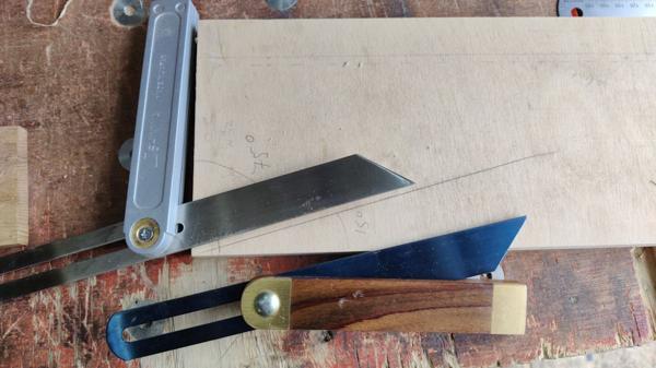
I dug out a bit of plywood with a 90° corner and marked a line on it at 15° to the long edge. I then used that to set up a pair of sliding bevels, one at 75° and one at 15°. I'm not sure that I need the 15° one yet, but I figured it was a sensible thing to do while I was setting the other on up.

2025-07-06-09-setting-up-sliding-bevels_600.jpg


The CAD model has changed a little (although you'd have to look carefully to spot it!) from the last time I shared it:

2025-07-06-cad-latest-model-with-inset-barefaced-tenon_600.jpg


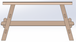
The main differences are that I've moved the stretchers slightly lower and I've changed the stretcher tenons to be bare-faced (as you can see in the inset image). Given the lack of a face shoulder, I also increased the size of the edge shoulders to 15 mm. With those changes made, the CAD model could be used to work out where the mortice needs to go in the leg.

The next job was to decide which end of the leg was the foot and mark the bottom end angle (in roughly the right place, but not worrying too much about precision at this point). I could then mark two positions: one 265 mm up from the heel and one 45 mm further up from there.

2025-07-06-10-marked-mortice-location_600.jpg


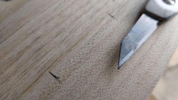
Those two positions got marked across the join line with a knife:

2025-07-06-11-close-up-of-mortice-knife-marks_600.jpg


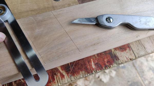
The sliding bevel (set to 75°) could be used to mark the shoulders of what will be a mortice:

2025-07-06-12-transfer-marks-across-inside_600.jpg


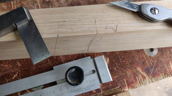
A square and an edge distance gauge thing marked the depth of the mortice (20 mm in each half to match the 40 mm thick stretcher):

2025-07-06-13-marking-down-edges_600.jpg


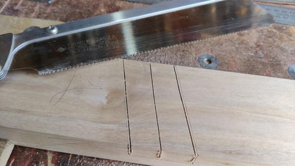
It was then a fairly simple process of sawing...

2025-07-06-14-sawing_600.jpg


... chiselling...

2025-07-06-15-chiselling_600.jpg


... and then two of my favourite woodworking jobs: chopping shoulders...

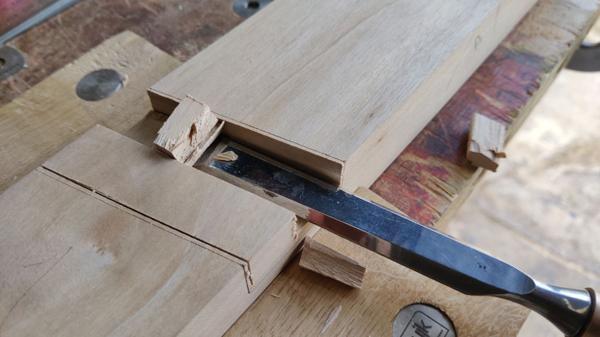
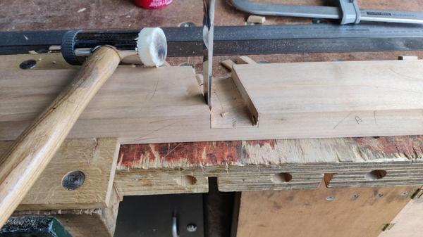
2025-07-06-16-chopping_600.jpg


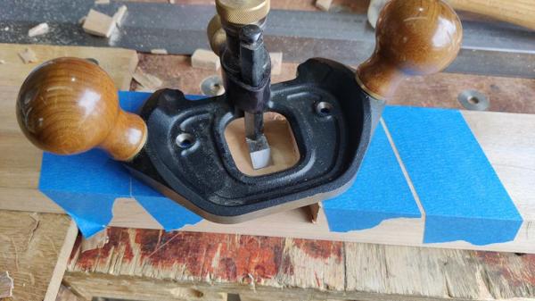
... and router planing (with the depth stop set for a consistent depth on each half):

2025-07-06-17-routering_600.jpg


The masking tape is there just in case any wood chips get underneath the router plane base: they'll tend to tear the tape (which will be obvious) and are less likely to damage the glue face.

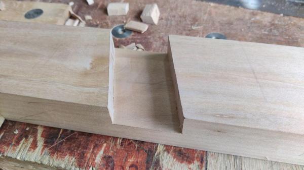
One half done:

2025-07-06-18-one-half-done_600.jpg


After lining the brass pins up with their corresponding holes, I could push the two leg halves together and I was very pleased to see the mortice sides lining up nicely:

2025-07-06-19-they-line-up_600.jpg


The size is also about right:

2025-07-06-20-size-is-right_600.jpg


The stretchers are currently a shade over 40 mm and the hole is a shade under, which felt right to me. Once I've got all the legs glued together, I can plane the stretcher faces slightly to get a nice fit (probably very slightly undersize to allow for expansion of the stretcher).

I could probably glue that leg together now, but I don't think there's a rush really so I'll probably do all four at the same time once all the stretcher mortices have been cut.
 
It’s all very neat and clean work up to now Al.
Now the panel pin thing, it’s normal to hammer the pins in and then nip the heads and most of the length off with a pair of pincers which touch the wood- sounds daft but the cutting edge is ground back a little which leaves a tiny very spiky spike, it is this that’s used as a locator, same spikes that have been on the bottom of my sharpening stone box for the last 50y, just press the box down onto the sharpening bench and it stops it moving. The other thing is with long shanks left it’s not so easy to line up the two halves before pressing them together.
Be interesting to see if I’m alone doing it this way.
 
It’s all very neat and clean work up to now Al.
Now the panel pin thing, it’s normal to hammer the pins in and then nip the heads and most of the length off with a pair of pincers which touch the wood- sounds daft but the cutting edge is ground back a little which leaves a tiny very spiky spike, it is this that’s used as a locator, same spikes that have been on the bottom of my sharpening stone box for the last 50y, just press the box down onto the sharpening bench and it stops it moving. The other thing is with long shanks left it’s not so easy to line up the two halves before pressing them together.
Be interesting to see if I’m alone doing it this way.
Thanks Ian. I'll try that on the next one.
 
I don't know how long it'll be before the IP blacklist on thewoodhaven2 gets removed & I can post from my laptop again (I really don't want to disable the protection).

In the meantime, if anyone wants to read what I would have posted here yesterday, the same content is here:

Build log page 9
 
Last edited:
Dr Al wrote:
"I'm at that lovely point in a project where I'm cutting joinery (which I enjoy), but as I've only done half of each joint (and hence can't check them), I can assume that they're absolutely perfect!"

I can certainly recognise that stage!
 
I've added woodhaven2's IP address to the "whitelist" of my malware protection software for now: I was getting frustrated at reading the forum on my phone. Hopefully the abuse from the server will get sorted soon and it will come off the blacklist. For now I've put a regular reminder in the diary to check as I always feel a bit edgy about having whitelist entries in protection software.
Anyway, as I can now get on the site via the laptop again, I'll post the two entries that were linked to above...
 
Posted 9/7/2025

I've managed a few hours of garage time spread out over the last couple of evenings: I'm trying to make the most of any time I can bear to be out there as the forecast for the coming weather is for 33°C and I'll be doing what I can to hide from that while dreaming of air conditioning.

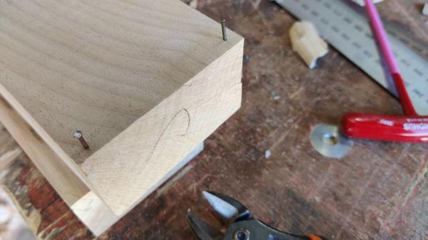
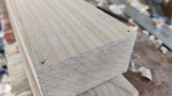
The other three leg mortices proceeded largely the same as the first one. I only changed two things about the process. Firstly, I followed some advice from Ian and ditched the brass pins in favour of some simple 12 mm panel pins, which were banged in...

2025-07-09-01-panel-pins_600.jpg


... then cut off flush-ish with a pair of side cutters:

2025-07-09-02-chopped-off_600.jpg


That leaves plenty of protruding steel to help me line things up (but will probably upset my saw more if I run into them!)

The other minor change is that I started using a 12 mm chisel for roughing out the bottom of the pocket (pre router plane). The only reason for that was to help extend time-between-sharpening of the 16 mm one (which is my default choice if there isn't a reason to use a smaller or bigger one) I'm using for the shoulder lines.

The Sycamore does leave a lovely finish when you chop the end grain:

2025-07-09-03-lovely-chopped-finish_600.jpg


Anyway, the last three marked up and two of those chopped out yesterday and the last one finished today:

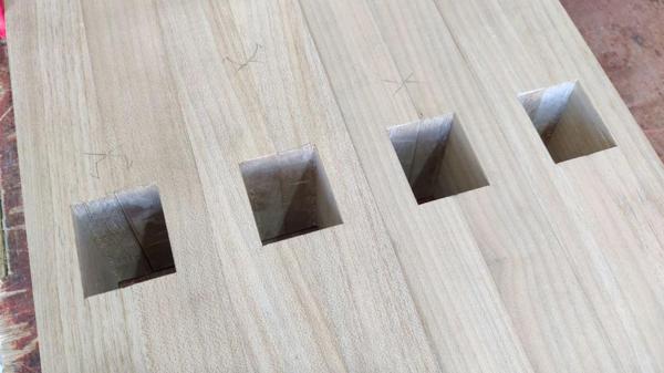
2025-07-09-04-four-mortices-done_600.jpg


I'm at that lovely point in a project where I'm cutting joinery (which I enjoy), but as I've only done half of each joint (and hence can't check them), I can assume that they're absolutely perfect!

If the heat is still bearable tomorrow evening I think I'll glue the leg halves together. After that, the next job is probably to sort out the unplaned face (the opposite side to that in the photo above) and pass a smoothing plane over the (thicknessed but yet to be planed) side faces. That all sounds like hard work if it's as hot as predicted, but I might manage a little in the weekend mornings.

I then need to get started on the big to-be-wedged mortices that will house the cross piece tenons. The original plan had been to do those at the same 15° that the legs are splayed (to vertical) on the long axis, but I've decided to change the side-to-side splay to be 8° (to vertical again, so 16° included angle). That'll reduce the stability a little, but hopefully it'll still be fine.
 
Posted 10/7/2025

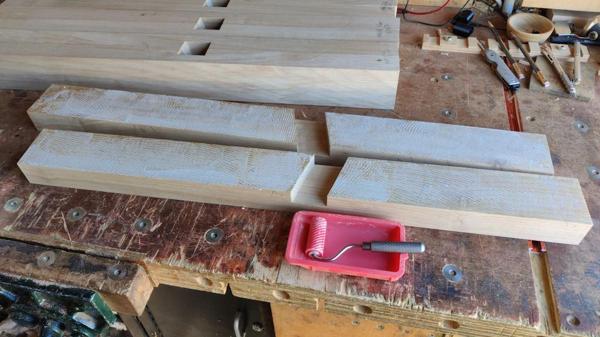
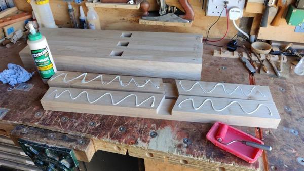
I decided to brave the heat and get the legs glued together this evening. I started by daubing on some glue:

2025-07-10-01-glue-daubed-on_600.jpg


That got spread out with a silicone roller:

2025-07-10-02-rollered-around_600.jpg


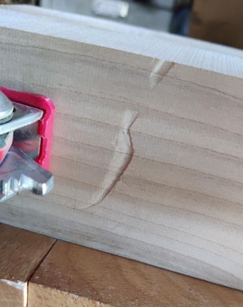
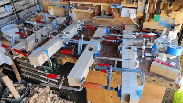
It was then a case of applying lots of clamps to squeeze it all together. The first one didn't go great: the brass pins weren't that good for keeping it in line, so I ended up using some extra temporary clamps to pull things into alignment. Then, after it was all done and the leg had been moved out of the way, two of the clamps slipped (I think I'd used some clamping pads that were a bit too small) and made a couple of deep indentations in the face:

2025-07-10-03-nasty-gash_600.jpg


Hopefully those will come out with a bit of steam iron attention when it's cool enough to contemplate such a thing, but the legs will be planed quite a bit more before they're finished, so worst-case they just end a little thinner.

The rest of the legs went together better with no clamp-jumping. There was still a bit of persuasion required to get them in-line: the steel panel pins didn't see to have that much effect on holding things true. Nevertheless, it's done as well as it's ever going to be now so we'll see what they look like when the clamps come off.

2025-07-10-04-lots-of-clamps_600.jpg
 
After work yesterday, it was far too hot (33°C) to even contemplate going out to the workshop so I just spent the afternoon hiding from the sun and trying to find the coolest place I could. The heat also meant that it was very late by the time I managed to get to sleep, so this morning was a slow start and it was already getting pretty hot.

Nevertheless, I couldn't face the idea of spending the whole day hiding from the sun and getting bored out of my skull so I set up a fan in the workshop and made sure I had plenty of cold fizzy water and a spray bottle full of cold water to "spritz" over myself regularly. I then started with a job that has to be pretty low on the list of good things to do on an unbearably hot day: steaming out the dents I showed in the last post.

This is what it looked like after a few goes with a hot iron and a damp cloth:

2025-07-12-01-steam-iron_600.jpg


This is what it looked like after planing:

2025-07-12-02-after-planing_600.jpg


You can still feel the dent if you run your hand over it and it is still visible, but it's looking a lot better and I'm sure the leg will get a few smoothing plane passes before it's done so I think it's good enough for now.

The next job was a lot of planing to get the legs all somewhere near square (and square to the mortices). That was very hot work.

2025-07-12-03-hot-weather-for-planing_600.jpg


The joints aren't great. Some (like the one in the photo above) are absolutely fine. The worst one is that one that had the brass pins for alignment. The joint line is quite visible on that one:

2025-07-12-04-some-gappy-joints_600.jpg


A couple of the mortice halves ended up very slightly misaligned, but that was easily dealt with using my trusty 16 mm chisel:

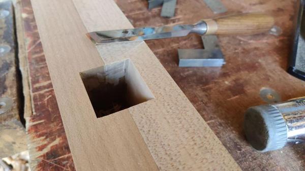
2025-07-12-05-some-misalignment-needing-tweaking_600.jpg


After all that planing in this heat, I needed a break, so I thought I'd come in and write this post. I'm seriously considering setting a 4am alarm for tomorrow and just accepting I'll be knackered for a lot of the day (at least that might mean I get to sleep more easily on Sunday night ready for work on Monday!). I'm not the best at mornings, but it would mean the temperature would be a bit more bearable for doing workshop stuff. Of course, I'd have to pick the jobs quite carefully: the next job is probably to chop the deep mortices for the cross pieces and I don't think I'd be very popular with the neighbours if I spent the early hours of the morning whacking mortice chisels with a mallet!
 
My 'shop is pretty well insulated so even with the door and windows open plus a fan pushing air around, it's more that flesh and blood ('specially mine) can stand, so until the current warm spell is dun n'dusted, it's off limits - Rob
 
I do feel obliged to point out that my little playroom may be crowded and too low ceilinged for Al to be jealous of, but being in the basement, it's the coolest room in the house. I don't want to do anything heavy but I might just retreat there for a while regardless :)

But that sounds smug, so I won't say it. Instead I'll express pleasure at how well you've recovered from those ghastly looking dents.

Even though you're not making a piece of drawing room furniture, I can see that you want it to be as good as possible, so I am pleased for you and admire your stamina.
 
I do feel obliged to point out that my little playroom may be crowded and too low ceilinged for Al to be jealous of, but being in the basement, it's the coolest room in the house. I don't want to do anything heavy but I might just retreat there for a while regardless :)

But that sounds smug, so I won't say it. Instead I'll express pleasure at how well you've recovered from those ghastly looking dents.

Thanks Andy. It was a bit of a relief to see them (mostly) disappear.

Even though you're not making a piece of drawing room furniture, I can see that you want it to be as good as possible, so I am pleased for you and admire your stamina.

Thanks again. I do get frustrated when the weather gets this hot. I'm not a great one for sitting around doing nothing. I don't mind an hour or to to read a book or watch a film but beyond that I start going stir crazy.

I've got two big fans running in the garage and I'm regularly spraying myself with water and that does seem to help a little. It's definitely not as enjoyable as woodwork can be though.

I doesn't help that I have a (self-imposed) deadline on this project and there are only five mostly-free weekends left after this one (and on two of those we'll be out for one of the days). That doesn't give a lot of time and there's a lot still to do.
 
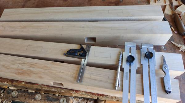
I'm having to do things in relatively short stints, but before lunch I marked up all the mortices for the short cross-pieces. I started by using my two edge-distance gauge things and a square to mark (with knife and pencil) the locations of the mortices on the inside faces:

2025-07-12-06-marked-mortices-on-inner-faces_600.jpg


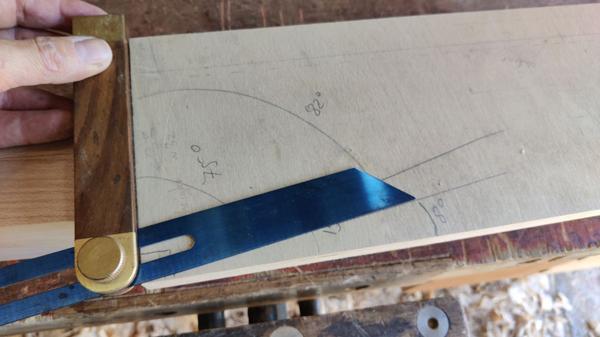
I got one of my sliding bevels and set it up for 82° as I've decided on an 8° splay for the legs:

2025-07-12-07-setting-up-bevel-for-8-degrees_600.jpg


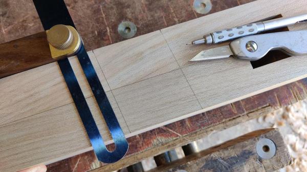
I could then use it to transfer the mortice edges around the face (with a knife mark on the corners and a pencil line across the face to help avoid mistakes later):

2025-07-12-08-marking-round-face_600.jpg


After a quick sanity check to make sure that each pair had mirrored angles...

2025-07-12-09-sanity-check_600.jpg


... I could mark the outer edge as well:

2025-07-12-10-marking-outer-edge_600.jpg


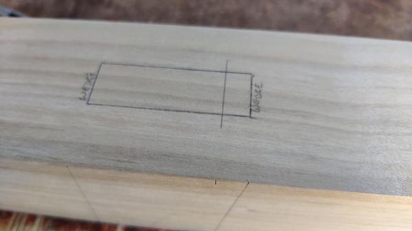
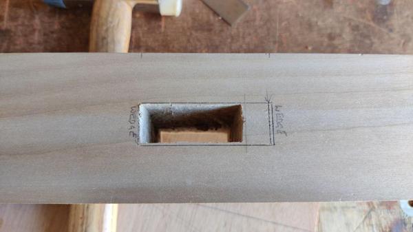
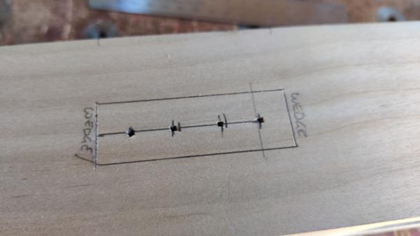
The "wedge" writing is showing me clearly which face will have the mortice opened up so that the tenon can be wedged. The area around where the writing is will go, but I'll cut the mortice as if it isn't being wedged initially and then expand it later.

The pencil line about a fifth of the way from the right-hand edge is there to show me how much of the mortice could be cut straight down (i.e. ignoring the bevel angle). I thought that might be helpful as I could chop out the central bit square and then sort out the angled sides afterwards.

I haven't decided yet how I'm going to approach these enormous mortices. They're 20 × 60 mm and 80 mm deep so they're by far the biggest mortices I've ever tried to cut (if you don't count the other ones in these legs that I cut as a pair of half-laps). It's quite tempting to drill out a lot of the waste, but I am conscious that when I've tried that before it has made the subsequent chiselling a bit more awkward.
 
Last edited:
I've very little experience of anything on that scale but I would bore most of the wood out and chisel away the rest.
 
2025-07-12-10-marking-outer-edge_600.jpg


The "wedge" writing is showing me clearly which face will have the mortice opened up so that the tenon can be wedged. The area around where the writing is will go, but I'll cut the mortice as if it isn't being wedged initially and then expand it later.

The pencil line about a fifth of the way from the right-hand edge is there to show me how much of the mortice could be cut straight down (i.e. ignoring the bevel angle). I thought that might be helpful as I could chop out the central bit square and then sort out the angled sides afterwards.

I haven't decided yet how I'm going to approach these enormous mortices. They're 20 × 60 mm and 70 mm deep so they're by far the biggest mortices I've ever tried to cut (if you don't count the other ones in these legs that I cut as a pair of half-laps). It's quite tempting to drill out a lot of the waste, but I am conscious that when I've tried that before it has made the subsequent chiselling a bit more awkward.

If you own a decent sized, accurate router, I'd suggest that you could cut these relatively easily taking four cuts from both sides in light steps. Each cut would be referenced off the sides (assuming dead parallel, which they would be) using the router fence. All you'd then need to do is to clean up the ends with a sharp chisel and maul.

Cutting from both sides is easy and the way I made the mortices on the 'Owl Cabinet' recently completed, although Paduk is significantly harder than Sycamore, so my machining of necessity was pretty slow. Merely a suggestion - Rob
 
Yes I would drill away most of the waste, central line from a marking gauge and a 16 or 18mm Forstner bit using the point in the scored line. As it’s a through mortice I would attack from both sides.
 
I've very little experience of anything on that scale but I would bore most of the wood out and chisel away the rest.

Yes I would drill away most of the waste, central line from a marking gauge and a 16 or 18mm Forstner bit using the point in the scored line. As it’s a through mortice I would attack from both sides.

Thanks both.

If you own a decent sized, accurate router, I'd suggest that you could cut these relatively easily taking four cuts from both sides in light steps. Each cut would be referenced off the sides (assuming dead parallel, which they would be) using the router fence. All you'd then need to do is to clean up the ends with a sharp chisel and maul.

Cutting from both sides is easy and the way I made the mortices on the 'Owl Cabinet' recently completed, although Paduk is significantly harder than Sycamore, so my machining of necessity was pretty slow. Merely a suggestion - Rob

Thanks, but since I sold my table saw, the electric router has been promoted to "least favourite woodwork tool". I see it as a tool of last resort. I'd much rather do it without using screaming monsters that need ear defenders etc.
 
For the first couple of mortices, I decided to try two approaches and see which I preferred (I did these before reading the posts from Ian & Andy!). For the first one, I attacked it with my biggest mortice chisel:

2025-07-12-11-chopping-first-side_600.jpg


I kept going with that until I was about half-way down:

2025-07-12-12-about-half-way_600.jpg


It was quite a bit easier than I expected it to be to be honest. The big chisel went through the Sycamore quite easily and, as I was cutting a pocket that's a lot wider than the chisel, it was quite easy to dig the removed wood out of the pocket. Mostly I did that with the chisel, but the pocket's big enough I can get my finger in there and that was helpful a few times.

Once I'd gone half-way through, I flipped it over and attacked it from the other side until I was all the way through on the straight portion.

2025-07-12-13-through-from-other-side_600.jpg


You may notice in that photo that there are two knife lines on the right-hand side of the mortice. That's because I somehow mis-marked the location of the angle when I was marking up that mortice. The inner mark is the correct one, but the outer one will disappear when I open the hole up for the wedge, so it isn't really a problem.

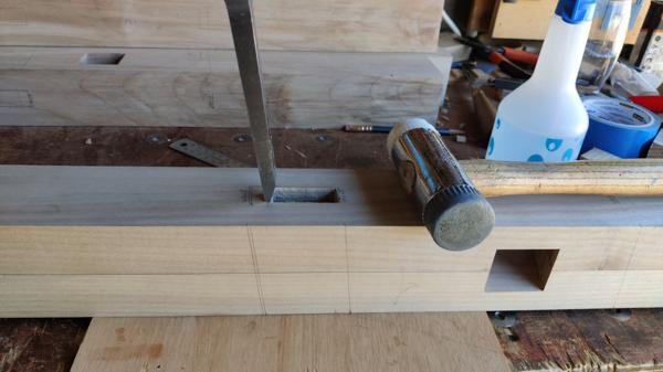
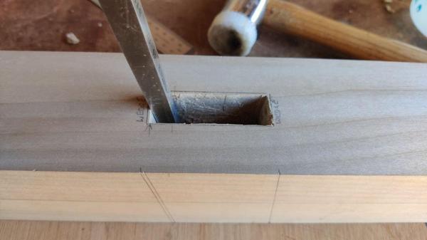
Next, I chopped down the ends, following the angle (from the side pencil mark) by eye.

2025-07-12-14-cutting-angled-bits_600.jpg


This photo makes it look like the angle's completely wrong, but that's just a photo oddity:

2025-07-12-15-cutting-angled-bits-2_600.jpg


In the last two photos, you can see the two parallel angled pencil marks: the mistake and the correct one.

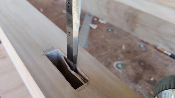
The last thing to do was to use my 18 mm chisel to pare the sides...

2025-07-12-16-paring-sides_600.jpg


... leaving a lovely finish that will never be seen again:

2025-07-12-17-first-mortice-done_600.jpg


For the second mortice, I got a 15 mm drill bit out:

2025-07-12-18-drill-bit_600.jpg


A line of centre marks were added with an awl:

2025-07-12-19-centre-marks_600.jpg


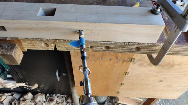
I could then clamp the board to the bench and drill parallel to the pencil marks, using the keyring to make sure I was drilling horizontally:

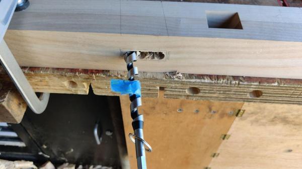
2025-07-12-20-drilling-first-side_600.jpg


After going about half-way through (with the masking tape as reference), I flipped the board round and came in from the other side:

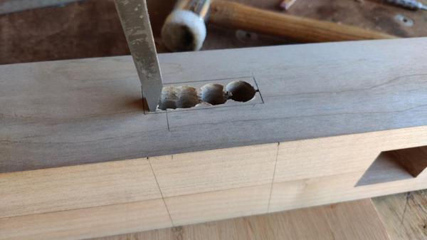
2025-07-12-21-drilling-second-side_600.jpg


The ends got cleaned up with the mortice chisel...

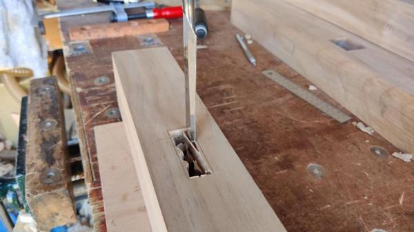
2025-07-12-22-cleaning-up-the-ends_600.jpg


... and then everything else was done with the 18 mm bevel-edge chisel:

2025-07-12-23-back-to-bevel-edge_600.jpg


With that, both of the mortices are done in the first leg:

2025-07-12-24-two-mortices-done_600.jpg


As to which method I prefer... I'm not sure.

I didn't time either of them so I don't know which was quicker (I'd guess the drill, but the tidy-up and paring felt like it took quite a while). I quite enjoyed the mortice chisel and it was good practice so that's something, but then I don't do much hand-drilling, so that's probably good practice too!

I think what I'll probably do is repeat the exercise on the next leg (doing one with the mortice chisel and one with the drill) but with a stopwatch running so I can see which is actually quicker. It's probably better to time the second attempt as there will be less pondering and deciding how to go about things next time.

Having said that I'll time it, I won't necessarily choose the quicker one: if I decide I enjoyed one more than the other, then that one will win regardless of duration.
 
Well, the results are in and they're rather unambiguous. I've done two more mortices, one with the mortice chisel and one with the drill brace, so I'm halfway there now:

2025-07-12-25-two-legs-done_600.jpg


The mortice one took half-an-hour in total, with 18 minutes spent chopping straight through, 7 minutes chopping the angled ends, 2 minutes paring the sides and 1 minute tidying up the ends.

The drilled one took 21 minutes in total, with 8 minutes marking and drilling followed by 13 minutes of chopping, paring and tidying up.

The difference was bigger than I expected. As to which I enjoyed more, it probably was the mortice chisel, but there wasn't much in it. I haven't decided what to do about the remaining sockets; I might well continue with one of each on each leg! If I do manage to get up early tomorrow, then I might do all the drilling of all the mortices (as it's quiet) and then sort out the chopping later on in the day. However, I've also got a metalwork (milling machine) job I want to get on with and that would be ideal as it'll be quite quiet and that end of the garage is far worse in the heat than standing near the door at the woodworking bench.

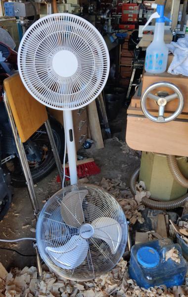
I'm really, really pleased with how today has gone. I'd half-expected to get to the end of the weekend having done nothing more than perhaps undoing the clamps on the glued-up legs. Instead I've managed to plane them all and chop half the remaining mortices and all by the end of Saturday. I've needed regular breaks and I've drank litres and litres of water, but it's been good. I couldn't have done it without the atomiser bottle to squirt water all over myself and the two big fans that have both been pointing at me and running at full power the whole time I've been out there:

2025-07-12-26-two-big-fans_600.jpg
 
Well, the results are in and they're rather unambiguous. I've done two more mortices, one with the mortice chisel and one with the drill brace, so I'm halfway there now:

2025-07-12-25-two-legs-done_600.jpg


The mortice one took half-an-hour in total, with 18 minutes spent chopping straight through, 7 minutes chopping the angled ends, 2 minutes paring the sides and 1 minute tidying up the ends.

The drilled one took 21 minutes in total, with 8 minutes marking and drilling followed by 13 minutes of chopping, paring and tidying up.

The difference was bigger than I expected. As to which I enjoyed more, it probably was the mortice chisel, but there wasn't much in it. I haven't decided what to do about the remaining sockets; I might well continue with one of each on each leg! If I do manage to get up early tomorrow, then I might do all the drilling of all the mortices (as it's quiet) and then sort out the chopping later on in the day. However, I've also got a metalwork (milling machine) job I want to get on with and that would be ideal as it'll be quite quiet and that end of the garage is far worse in the heat than standing near the door at the woodworking bench.

I'm really, really pleased with how today has gone. I'd half-expected to get to the end of the weekend having done nothing more than perhaps undoing the clamps on the glued-up legs. Instead I've managed to plane them all and chop half the remaining mortices and all by the end of Saturday. I've needed regular breaks and I've drank litres and litres of water, but it's been good. I couldn't have done it without the atomiser bottle to squirt water all over myself and the two big fans that have both been pointing at me and running at full power the whole time I've been out there:

2025-07-12-26-two-big-fans_600.jpg
Good quantitative study! Also nothing worse than having sweat running into your eyes.
 
Good quantitative study! Also nothing worse than having sweat running into your eyes.

Yeah, that's not a nice feeling, is it?!

It's amazing what a difference the little atomiser bottle makes though. Without it the fans just feel like they're moving hot air around but with a spray on the arms & neck you get a lovely cool breeze.
 
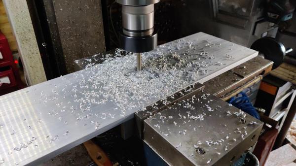
I made it into the workshop at 4.30am and it was a lovely temperature. After a bit of rearrangement of bandsaws and clutter, I set up a recently acquired bit of 10 mm thick aluminium plate in the milling vice and attacked it with drills, taps and an end mill:

2025-07-13-01-early-morning-milling_600.jpg


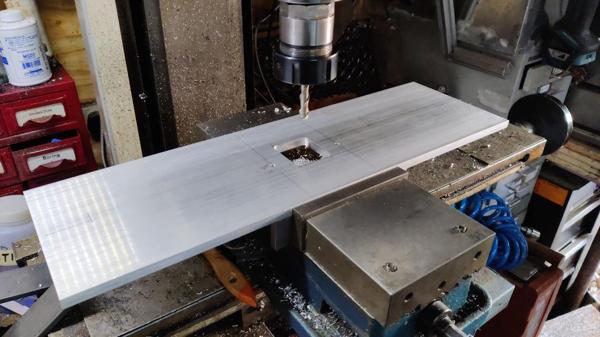
After tidying up the swarf:

2025-07-13-02-after-sweeping_600.jpg


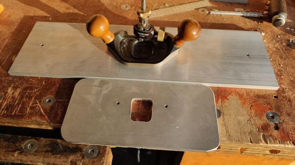
It's a new, thicker & larger version of my router plane base; here it is next to the old one:

2025-07-13-03-new-base-needs-handles_600.jpg


It still needs the corners rounding off and at some point I'll make some handles to attach to those 6 mm (and countersunk from underneath) holes near the ends, but it's usable as it is. When I was doing the big angled bridle joints on the garden table, I found that, while the smaller aluminium plate helped a lot, it wasn't big enough for getting at the extremes of the joints. As this bench is going to have some fairly hefty tenons, it seemed a sensible time to upgrade the base plate.

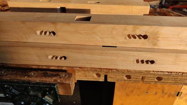
With that done, it was 5.30am and still too early to be making much noise so I got the brace out and drilled through all the mortices:

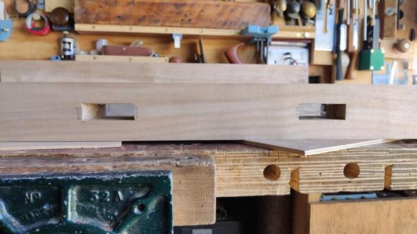
2025-07-13-04-drilled-holes_600.jpg


The sun was coming into the garage by that point (which only happens in the very early morning in the weeks around the summer solstice). That and the fact it was still too early on a Sunday morning for noisy hammering made me decide that it was time for coffee and breakfast! It was nice to be able to sit in the garden (which is still in the shade) for breakfast: by the time I'm usually up and about at the weekend, the sun is already beating down on the garden and I retreat indoors.
 
Back
Top