• Hi all and welcome to TheWoodHaven2 brought into the 21st Century, kicking and screaming! We all have Alasdair to thank for the vast bulk of the heavy lifting to get us here, no more so than me because he's taken away a huge burden of responsibility from my shoulders and brought us to this new shiny home, with all your previous content (hopefully) still intact! Please peruse and feed back. There is still plenty to do, like changing the colour scheme, adding the banner graphic, tweaking the odd setting here and there so I have added a new thread in the 'Technical Issues, Bugs and Feature Requests' forum for you to add any issues you find, any missing settings or just anything you'd like to see added/removed from the feature set that Xenforo offers. We will get to everything over the coming weeks so please be patient, but add anything at all to the thread I mention above and we promise to get to them over the next few days/weeks/months. In the meantime, please enjoy!

Post a photo of the last thing you made...

Nicely done Doug, could you remind me about the post savers pls? Was it shrunk coke bottles?

Those scalloped ends look difficult to get right Rob, I can think of a few ways to do them but none are easy or foolproof.
Ian
 
Cabinetman":36kja238 said:
Nicely done Doug, could you remind me about the post savers pls? Was it shrunk coke bottles?

Ian


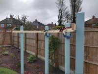
These are the post savers Ian
https://www.ebay.co.uk/itm/144051604929 ... iUQAvD_BwE
There’s a 30 second video showing their installation, quick & easy. Most posts rot off at the level of the ground or top of the concrete if concreted in so these prolong the posts life.
 
Cabinetman":2de47dhb said:
Those scalloped ends look difficult to get right Rob, I can think of a few ways to do them but none are easy or foolproof.
Ian
Hand planed across the grain with a convex soled plane to form the depression, then scraped and finally sanded - Rob
 
Doug":398holkt said:
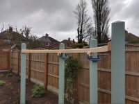
......Next up will be laminated curved pine rails attached to the posts near the top....

I look forward to seeing that. Did you make the formwork to the same radius as the circle of the posts, or a tad smaller to allow for springback? And did you have enough clamps? ;) :lol: :lol: Boatbuilders tend to use epoxy for big laminations. What did you use?
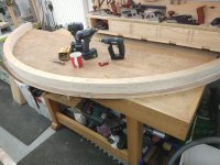
 
I used the 3/4” plywood template I’d set the posts out with as a base for the template for clamping the laminations.
When I cut the base I also cut several 2” wide strips of ply to the same radius. I simply used a marking knife to scribe a line 1” back off the curved edge of the base & fixed the strips to this line

CFAC9F3B-E17B-4A4E-9FEB-A426317BD92B.jpeg

If you look carefully you can see saw cuts in the back of the curved strips about half the depth of the timber this allowed me to adjust the strips to the new radius of the scribed line.
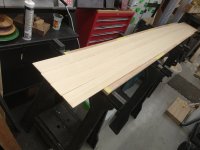
The timber I used for the laminations is 70 x 5mm five in total 3m long,here they are waiting to have glue applied to them.

EA3A0BCC-87E1-442A-A1FD-1CCE42973585.jpeg

The glue I’m using is Aerolite up 4145 urea resin which as this is going to be painted with Superdec I figured would be good enough plus I’ve already got it.
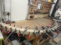
The laminations clamped in the jig, plenty of clamps ;)

1B93B05B-7782-4CB8-AD9A-FA522C775E30.jpeg

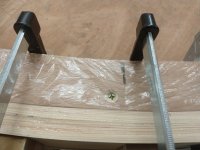
Cling film was used to stop the laminations sticking to the jig, this photo also shows the slot that allowed me to reduce the radius slightly of the curved strips to allow for spring back & also the slightly smaller radius of the inside of the curve.

D904617E-0C46-499A-A7FC-9B4627F3FDD2.jpeg
 
No hints yet from me, but what I thought was an interesting story, we were chatting over a cup of coffee in the office and the owner said when he was about my son's age (25) he made his "dining and everything" table 10 feet long out of Santos Rosewood. I've never used it but it is extremely heavy and dense like ebony but with figured grain like a pretty rosewood. He hand planed it (wide planks) (he was fit then he said) but you couldn't use a wooden plane because the very hard ebony like wood would destroy the plane mouth.
 
Nice, Doug.

There's something about laminations done well which really gladdens my heart. No idea why. A solid continuous former is something of a luxury.
 
Cabinetman":3d9ay3l3 said:
Nicely done Doug, I do like laminated forms, and that is going to look really classy when it’s done.
Ian

Mike G":3d9ay3l3 said:
Nice, Doug.

There's something about laminations done well which really gladdens my heart. No idea why. A solid continuous former is something of a luxury.

Thanks both, it’s a satisfying process, I want to put a chamfer on the top of the rail to help shed water which will be an interesting challenge


AJB Temple":3d9ay3l3 said:
No hints yet from me, but what I thought was an interesting story, we were chatting over a cup of coffee in the office and the owner said when he was about my son's age (25) he made his "dining and everything" table 10 feet long out of Santos Rosewood. I've never used it but it is extremely heavy and dense like ebony but with figured grain like a pretty rosewood.
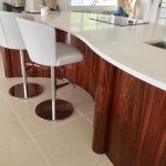
This is Santos Rosewood Adrian, not my work well the pillars are I turned those before they were veneered but it is a most striking timber.
B6AA9D34-1BFC-4031-9B48-C8841DDF46D4.jpeg
 
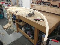
Progress, this was the curve straight out of the jig pleased to say it fitted a treat.

1942404F-3D17-4DAD-A99E-5BED9918A65A.jpeg

After cleaning up the edges it was time to add the chamfer this was done with a Stanley No20 compass plane freshly sharpened for the task

800DE69A-5732-4D31-BEAA-8F35424865A6.jpeg

This is me completing the planing task, where’s the grey haired old man emoji :lol:

https://www.instagram.com/reel/CpP8CmUj ... MyMTA2M2Y=

Finally trimmed to length & test fitted

3B582D10-C693-4496-A533-72AFCFD41FBB.jpeg

Rinse & repeat for the other side & it will be time to get the paint out
 
Great stuff Doug, and you've got that compass plane working nicely.
 
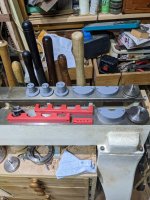
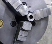
I printed a few storage aids for lathe stuff
PXL_20221203_193603193.jpg
Chuck/face plate mounts and something to keep the inserts for the O'Donnell jaws to hand instead of them lurking at the bottom of a draw.

If anyone would like a chuck mount, let me know and I can print you some.
 
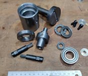
Today & yesterday I made these bits (apart from the bearings and screws, unsurprisingly):

bits.jpg

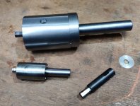
I then put them together to make this (the big one, with its little brother that I made from a kit a while ago):

assembled.jpg

I then tried it out and made this...

first_test.jpg

... 8 mm AF, 15 mm deep hexagonal hole in a bit of 16 mm stainless steel bar.

The design was very closely based on the one from the Hemingway Kit that I'd previously made. I basically just doubled most of the dimensions and then tweaked it for 12 mm silver steel broaches and to suit standard size bearings (as you can't get bearings in exactly double the size of the ones in the Hemingway kit).

The Hemingway kit one will do up to 6 mm AF and up to 7 mm deep, but I want to be able to cut a 14‑ish millimetre deep, 8 mm AF hole for an upcoming project and I thought it would be fun to see if I could scale up the Hemingway design.
 
I have no idea what on earth you are talking about good doctor. What is this language you speak?
Whatever it is and whatever it does it looks well made to me.
 
Andyp":3pl4ee3q said:
........What is this language you speak?.....

I think it's from "Old Man and the Sea".

Well, that's the best I could do, anyway.
 
Thank you. As they say, every day is a school day. I had never ever wondered how hexagonal holes were made. Now I know and will never forget.
 
Cabinetman":1ntv3opj said:
Again mystified, but I’m sure it's very clever, could you describe in layman’s terms what a broach is and how it cuts none square holes please?
To give a good explanation would involve me fully understanding it, which I don't, but I'll have a go.

The hexagonal cutter is tilted off the lathe axis (by about 1°). It gets pushed into a hole (pre-drilled to the AF dimension of the hex) and as it contacts the workpiece it starts spinning with the work-piece.

Because of the 1° angle, each flat of the hex cutter moves along the axis slightly as the cutter & workpiece rotate. This nibbles away at the corners, pushing the excess material down into the hole.

That's the best description I can come up with. I'm sure there are slow-mo animations around that would explain it better
 
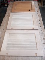
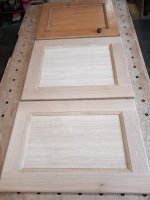
Quick infill job (not quick to do) 2 Oak Kitchen cupboard doors to match existing, for an insurance water damage job:

door 1.jpg door 2.jpg

Got to try and colour match now.
 
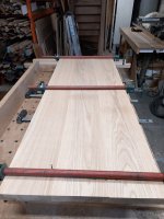
Another infill job, short length of Oak worktop:

worktop.jpg

Not glued up yet, too cold, 6 degrees in shop today, (I have now swung the middle board round).
 
Dr.Al":1g0bt70l said:
Cabinetman":1g0bt70l said:
Again mystified, but I’m sure it's very clever, could you describe in layman’s terms what a broach is and how it cuts none square holes please?
To give a good explanation would involve me fully understanding it, which I don't, but I'll have a go.

The hexagonal cutter is tilted off the lathe axis (by about 1°). It gets pushed into a hole (pre-drilled to the AF dimension of the hex) and as it contacts the workpiece it starts spinning with the work-piece.

Because of the 1° angle, each flat of the hex cutter moves along the axis slightly as the cutter & workpiece rotate. This nibbles away at the corners, pushing the excess material down into the hole.

That's the best description I can come up with. I'm sure there are slow-mo animations around that would explain it better

here you go folks.

https://www.youtube.com/watch?v=GWyHJVOxKK4

best explaination of a rotary broach I've seen.
 
Thanks Dave
Took some getting my head around it but I learned something. :eusa-clap:
 
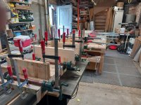
Nothing exiting, but as the weather warmed I got on to a glue up, never enough clamps!

clamping.jpg

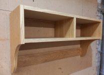
And while hanging around for that lot to cure, knocked up a coat rack shelf, things like these I make to go for local charity raffles (needs some hooks)

Coat rack shelf.jpg
 
Got asked to fit a hand rail for a nice old lad who I fitted a kitchen for last year, he’s a bit unsteady on his feet & wanted a rail to match his existing one but on the opposite side of the stairs.
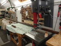
I couldn’t find anything commercially available to match so ended up making one only problem being it was 3.7m long which as the photos will show was a bit of a challenge in my workshop :? :lol:

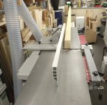
Surface planing up wasn’t too bad I just had to move the planer towards the centre of the shop.

CEF4CA3E-5D4A-4C0C-9F60-0CBF5AF3ABA3.jpeg

The thicknessing proved to be fun I ended up having to open the cupboard at the end of the workshop to let the wood pass into it, Instagram video of that here :lol:
https://www.instagram.com/reel/Cp0w6YAr ... NmNGQ3MDY=

Then the spindle moulder was moved to the centre of the shop luckily all of the machines are on casters & the spindle is higher than the worktop at the bottom of the workshop so this was the easiest bit of the machining.

3573093A-4363-4C39-B4AB-68604CA51D23.jpeg

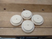
After a good sanding I turned up some some pattresses not only do I find it makes fitting handrails easier but it also spreads the load & stops the metal brackets digging into the plaster.

121FBFCB-EE9E-43C7-A618-DA64C1721051.jpeg

I’m hoping to get this fitted tomorrow so first thing I gave it a coat of Rubio monocoat oil


656B1476-1B39-42C3-83E0-EC997DC774A2.jpeg
 
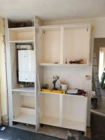
Probably one of the worst situations I have had to overcome in a long time, 600 wide * 600 deep bought in pantry unit to go around boiler, the wall to the right has been drylined & skimmed by a complete numpty, out vertically by 1" and with a belly in the middle, had to cut everything down to 440 deep to fit into the space and cut round pipe city & then scribe all the wall meeting faces to get it even close to looking neat, still got to go back and tidy it up, and finish the rest of the kitchen + a few internal doors to hang, its away and took me nearly 5 hours to get home on Friday... :cry:

boiler.jpg
 
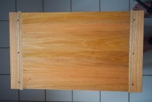
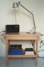
Before Christmas I started work on a bedside table, made a bit of progress then the festive season itself came and I ended up doing an hour here and an hour there. The loss of continuity was not good: I got out of my rhythm a couple of times and did daft things like mitring a tenon on the wrong edge or cutting a mortice on the wrong side, I had to make some components again from scratch. Lessons learned.

The top and shelf are of elm and the frame is of beech.

This was also my first attempt at breadboard ends. The four little white things are an attempt at decorative plugs. They're rubbish but the table is for me and frankly I didn't care at that stage. I know how to do them for the future though.

All in all, I'm quite pleased with it and it has definitely tidied up the space to the side of my bed.

Table III.jpg
 

Attachments

  • Table I.jpg
    Table I.jpg
    91.7 KB · Views: 74,005
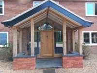
Always nice to go back to see a previous job, for extra work, made all this with the help of some friends, last year:

porch.jpg

Oak post are starting to weather up, but the door still looks like new.
 
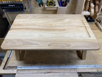
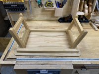
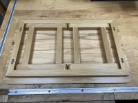
I made this table for my daughter as she likes to work sitting in bed. It’s made from odds and ends of beech I had in the garage which it gives it some “character”. There is also some character on the insides of the legs, but that was an unintentional feature from the manufacturing process!

252C530F-307B-430E-85EF-67F4EB4E7E0B.jpeg

B21716C5-8678-47FE-80D9-CE3F8ADE5535.jpeg

EB15B8B8-6E03-4FB0-93A5-E588FE06D2A4.jpeg

I have just finished it with several coats of Rustins danish oil which is very easy to use and seems to give reasonable finish.
 
HDJ, I feel that pain!

Andy, hour here, hour there. It's not ideal but you came through, good looking results too.

HDJ, impressive!

WW, that's a nicely done lap desk.


Sent from my Pixel 4a using Tapatalk
 
HOJ":13pthuzq said:
Always nice to go back to see a previous job, for extra work, made all this with the help of some friends, last year:......

That's nice Paul. A modern variation of the traditional. Is there a steel shoe penetrating the stone cap of the plinth to take each post foot?
 
Interesting design Paul. Looks like it was an economical use of timber and the design has embraced that.
 
Mike G":3q6u07w2 said:
Is there a steel shoe penetrating the stone cap of the plinth to take each post foot?

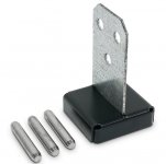
Mike, we have used the Simpson post bases in the past, such as these:
post base.jpg
They need a slot cut in the post end, most people cut a slot right through, which I don't like, we have a jig which bolts on to a chainsaw bar and uses a plunge action makes a nice neat job, sort of a mortice, any way, in this case we have SS threaded rods, drilled through the slate and into the full fill cavity, resin bonded in, then put up into the post base, again resin bonded & bedded on CT1 silicone to stop water drawing up the end grain (engineer on board & BC sign off)

AJB Temple":3q6u07w2 said:
economical use of timber
Adrian, the design had various iterations with the usual "Oak frame features" but on scale looked far to busy, there was also a consideration to close in with glass but decided against.
 
Back
Top