• Hi all and welcome to TheWoodHaven2 brought into the 21st Century, kicking and screaming! We all have Alasdair to thank for the vast bulk of the heavy lifting to get us here, no more so than me because he's taken away a huge burden of responsibility from my shoulders and brought us to this new shiny home, with all your previous content (hopefully) still intact! Please peruse and feed back. There is still plenty to do, like changing the colour scheme, adding the banner graphic, tweaking the odd setting here and there so I have added a new thread in the 'Technical Issues, Bugs and Feature Requests' forum for you to add any issues you find, any missing settings or just anything you'd like to see added/removed from the feature set that Xenforo offers. We will get to everything over the coming weeks so please be patient, but add anything at all to the thread I mention above and we promise to get to them over the next few days/weeks/months. In the meantime, please enjoy!

Heat Treatment Oven

You are probably aware of this but you need special cable called "compensating cable" to connect thermocouples. If you use plain copper you risk introducing significant measurement errors.

I'll explain why if anyone is interested.

Thanks. I was aware you needed special cable (I didn't know it was called "compensating cable"). The stuff I bought was just called "K-type thermocouple cable" - green and white stuff - is that the same thing?

Feel free to explain why as although I have a very vague idea of it all, I don't think I know it well enough to explain it to anyone else! My vague way of explaining it would be that a thermocouple is basically two dissimilar metals in contact, so if you use copper then you effectively introduce another thermocouple in-line and that screws up any chance of meaningful measurement. That's about as far as my understanding goes though.

Very impressive :cool:
{he who does not have a cooking clue as to what it means :(}

I was thinking to maybe follow along with our own build till the diagrams got all complex. :) No chance!

I was trying my best to explain stuff as simply as possible... I guess I failed :(
 
I was trying my best to explain stuff as simply as possible... I guess I failed :(
I look at the simplest circuit diagrams and struggle, Al - absolutely my problem, not yours. You can take a horse to water (etc.)!
 
Re compensating cable - yes cable marked type K is either compensating cable or actual thermocouple alloy in cable form.

Regarding why it's important, you are quite right, a thermocouple is two dissimilar metals in electrical contact which generate a minute electrical signal roughly proportional to temperature (it's non linear). However, there are two other thermocouples formed where the thermocouple leads join the usually copper conductors of the electrical measuring circuit and these also generate electrical signals that vary with temperature, these are called the cold junction. So... in order to measure accurately, you have to know the temperature of the cold junction and compensate for it.

Electronic measuring instruments measure the temperature of the connectors at the back of the housing and compensate for it. Easy ! BUT, that supposes that the thermocouple is connected directly to the instrument. If the thermocouple is remote, then there will be connecting leads and if these are copper wire, then the cold junction is effectively where the copper wire joins the thermocouple and measurement at the back of the instrument is no help. Hence the need to use either the actual thermocouple alloys in the connecting leads (expensive), or more usually, a cable called "compensating cable" made with alloys that have the same thermoelectric properties but are much cheaper to produce (they only have to withstand ambient temperatures). Any plugs and sockets or terminal blocks used to connect the thermocouple must also comply or spurious thermocouples may be created somewhere in the connecting circuit. I see you have the correct connectors, often forgotten.

One little piece of advice : the thermo electric signal is minute - around 0.04mV/°C. Associate the connecting cable with interference sources such as thyristor controlled heaters and you you give the measuring instrument a headache. Keep the cable runs well spaced and especially dont run them in the same duct or cable harness which looks nice and tidy but is the worst thing you can do.

Cheers and bon courage
 
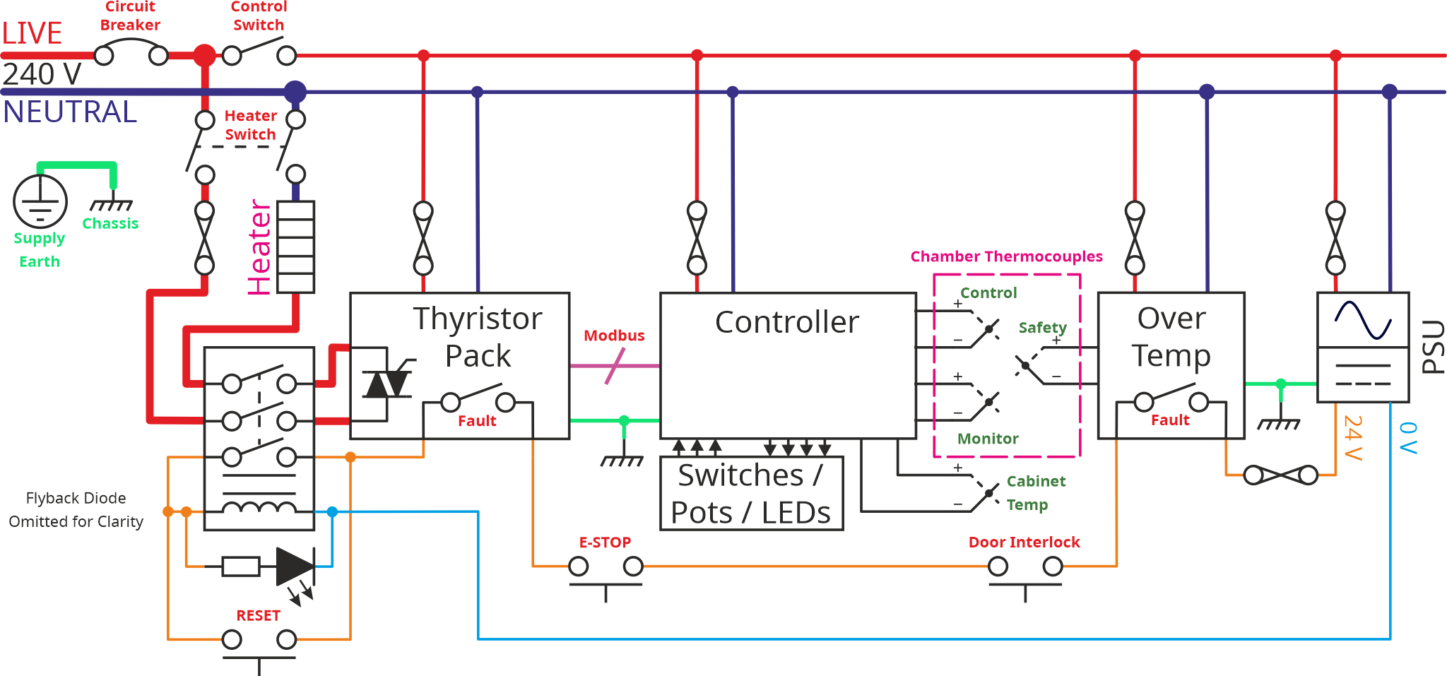
In the last post, I talked about a simpler version of the control cabinet schematic. Let's go back to the more complicated version that has become possible thanks to my generous benefactor!

ControlCabinetSchematic-AlternativeLayout_2024-12-19.png


The control part of this schematic is certainly more complex, but there aren't that many components involved. Starting on the right (and ignoring the power supply that I've already discussed), there's a simple over temperature monitor. This over temperature monitor (an Omron E5C2) has a simple dial on the front allowing you to set a threshold temperature of anything up to 1200°C. If the temperature goes above that threshold, it opens a switch (in the safety circuit) which will cause the contactor to open and hence the power will be disconnected. That's used as a safety device in case of any faults in the other parts of the system.

To the left of that over temperature device, there are a handful of thermocouples. One is used for the over temperature trip, one is connected to the controller to control the chamber temperature. The other two are there purely because the fancy "Eurotherm Nanodac" controller I'm using has lots of input channels, so I thought it would be interesting to try logging temperature in a couple of different places and seeing how it varies.

Next to the left is the Nanodac controller. This is a very fancy device with a big screen and lots of input/output connections. I'll be discussing the controller more in due course, but for now it can be thought of as the same as the simple PID controller I discussed before: it reads the temperature, then tries to drive the heater coil (via the thyristor pack) to get the temperature to the right level.

There are some switches, lights and pots (potentiometers: variable resistors in the form of a rotating knob that can be used to adjust something). Exactly what they'll be used for is yet to be determined.

The thyristor pack is the thing that controls the actual current through the heater. It's a very fancy one (called a Eurotherm EPack). I doubt I'll use many of its features, but the ability to run at a reduced current is definitely of interest.

The controller and the thyristor pack "talk to each other" via a Modbus TCP interface. I've never used Modbus TCP before, but I have used its serial equivalent, Modbus RTU. It's essentially a way for control equipment to send commands to other control equipment over an ethernet cable. From the point of view of the user (i.e. me), it's very simple: you plug the two devices together and then tell one of them what address to write to in the other; Eurotherm have sorted all hard work of making them talk.

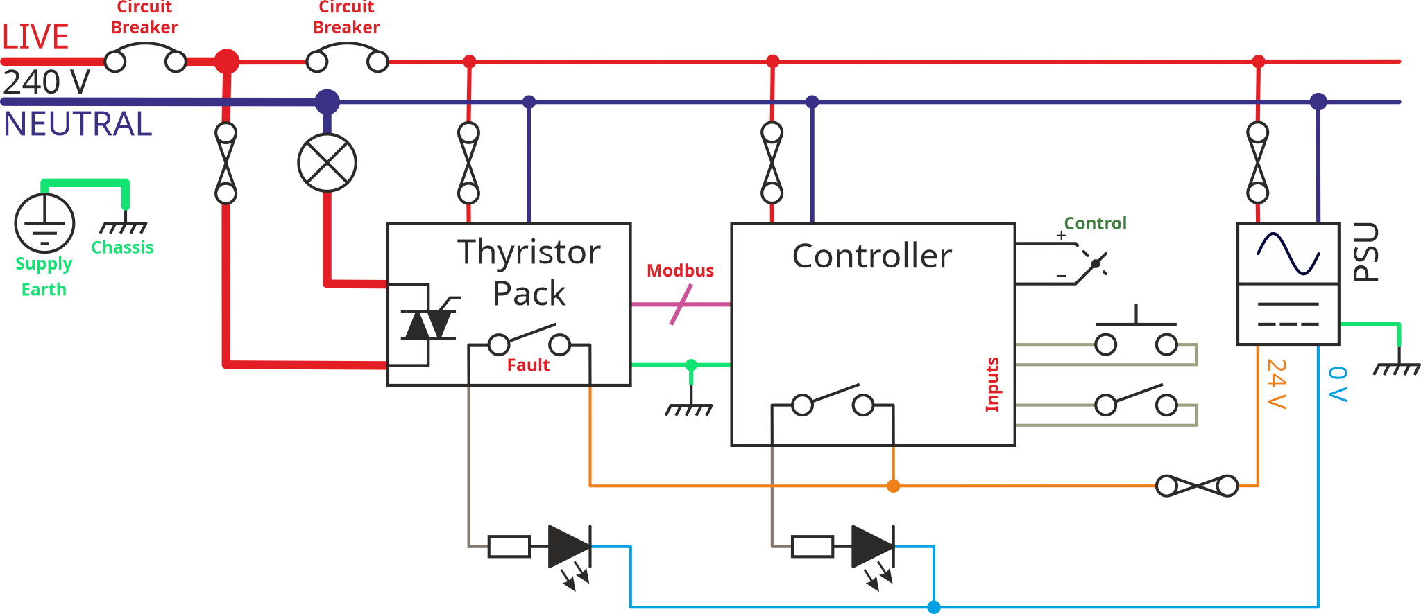
Over the Christmas break we'd arranged five nights in Lyme Regis with various family members congregating on two cottages in that beautiful town. I was fairly sure there would be a fair amount of "down-time" during the week, so I wanted to use that time to do some investigation into the fancy control gear. That thought led to yet another wiring diagram:

LightBulbTestSchematic-2024-12-21.png


This one is again very similar to previous versions, but most of it has been removed. The controller still talks Modbus to the thyristor pack, but the thyristor pack is now just driving a light bulb (shown as a circle with a cross through it). The fault output from the thyristor goes to an LED, as does one of the outputs from the controller. There are a couple of switches and a thermocouple going to controller inputs.

I set the 3D-printer going making a few mounting frames and then spent an inordinate amount of time wiring it up (for such a simple schematic you'd think it would be a quick job!)

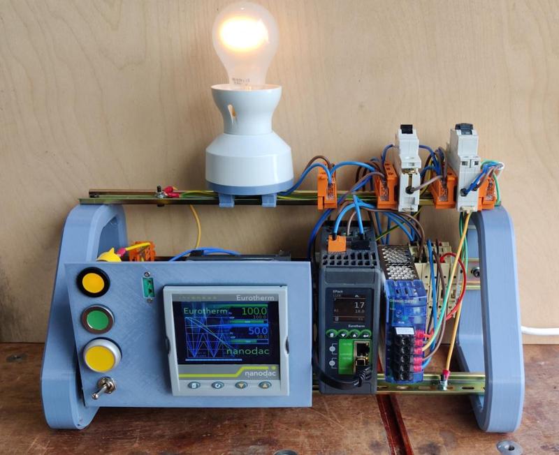
This is what it looked like when finished (the controller and thyristor pack both had configurations pre-installed by my generous benefactor as he'd tested them both using a similar set-up):

lightbulbtestframe-01_800.jpg


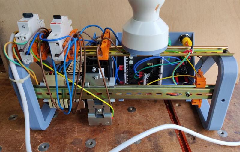
It looks like more of a rats-nest on the back:

lightbulbtestframe-02_800.jpg


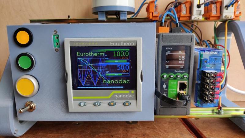
This close-up shot shows that big display on the fancy controller (when the photo was taken it was still in the process of booting up, which takes a little while):

lightbulbtestframe-03_800.jpg


To the left of the controller are a pair of panel-mounted LEDs (one yellow, one green), a yellow push-button and a toggle switch. There's also a socket into which a thermocouple can be plugged. To the right of the controller are the thyristor pack and a power supply.

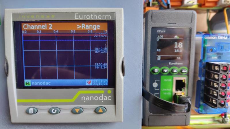
This photo shows what the controller looks like after it has booted up. It has several different options for what's shown on the screen; this was just what came up by default.

lightbulbtestframe-04_800.jpg


Over the course of the time in Lyme Regis, I managed (after getting over quite a few hurdles) to get the controller and thyristor pack at least partly tamed. The first thing I did was a very simple configuration that turned the green LED on and off according to the position of the toggle switch. Not exactly earth-shattering, but getting there required gaining quite a bit of understanding of the Eurotherm iTools software that is used to configure both devices.

After that, I made another simple configuration that set the output power (i.e. the brightness of the bulb) to a level proportional to the temperature of a thermocouple plugged into the socket. With that configuration, I could grab hold of the end of the thermocouple (thereby heating it) and the light would get brighter. Releasing the thermocouple would cause the light to dim.

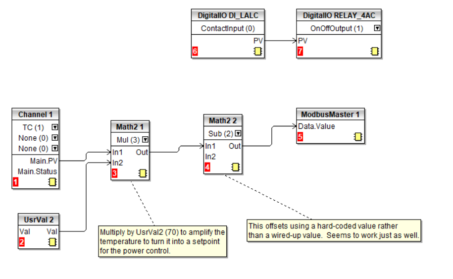
This is what those configurations looked like in iTools for the Nanodac controller (there's much more to it but I thought I'd share an overview):

2024-12-26-itools-wiring-for-switch-to-led-and-temp-to-brightness.png


The top half of that circuit just connects one of the inputs to one of the outputs. With the way I wired it up, that made the switch state affect the LED state: flipping the switch made the LED turn on or off.

The bottom half takes the measurement from the thermocouple (wired into Channel 1) and does some simple maths on it (multiplies it by 70 and then subtracts 1400) and then writes it (via Modbus) to the thyristor pack. The numbers used in the maths blocks were chosen fairly arbitrarily, but they result in a temperature range of 20°C to 35°C mapping to an output value of 0 to 1050. That lined up with what seemed to be the expected range of values from fully off to fully on for the thyristor pack. I'm still learning how the thyristor pack works so I don't think I can fully explain that bit yet!

That's it for now. I think that setting up the controller and thyristor pack is going to end up being the most time-consuming part of this project, but I'm quite enjoying playing with it and learning how it all works (and my generous benefactor has continued to be helpful by providing lots of support!) so I don't mind that at all. All being well, I'll be able to make the controller do some extra interesting things (beyond "simply" controlling the oven temperature).

I'm back home now and I'd like to start making some progress on the physical build of the chamber and the control cabinet, so the next post (or several) will probably be back to my normal style of build write-up.
 
I had a fairly slow start today but I've made quite a bit of progress nonetheless. The first job was to have a go at winding the heating element into a coil. On the youtube videos I've watched, they've generally done this by the very simple method of drilling two holes in a piece of wood (one tangential to the other) and using a cordless drill to turn a piece of steel bar onto which the element is wound.

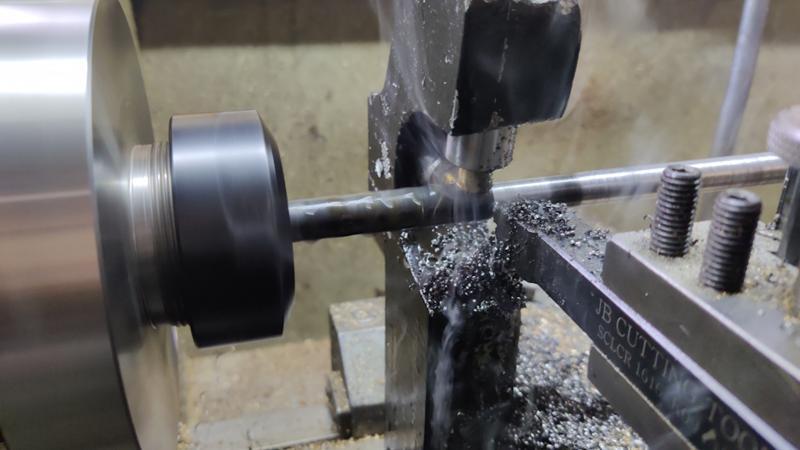
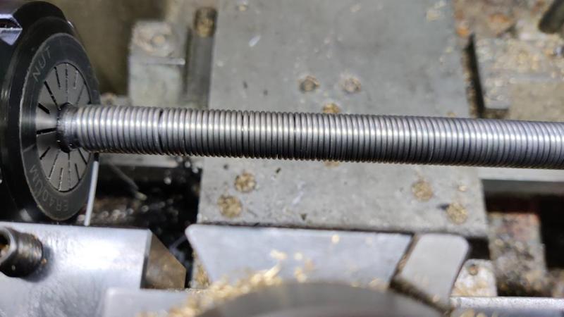
That method looks very fast and effective, but when do I ever choose fast and effective?! I thought it would be nice to do it under a little more control by turning the elements on the lathe. I was absolutely convinced I had some long lengths of 10 mm EN1A steel bar in stock, but after spending half-an-hour searching for them I gave up and got some 12 mm mild steel (I think it's S275 steel). I needed a length as long as possible and I didn't want it to be quite as big as 12 mm, so I drilled a centre hole in the end and then extended it as far out of the lathe chuck as I could (using a collet chuck as it's a bit shorter than my three-jaw chuck).

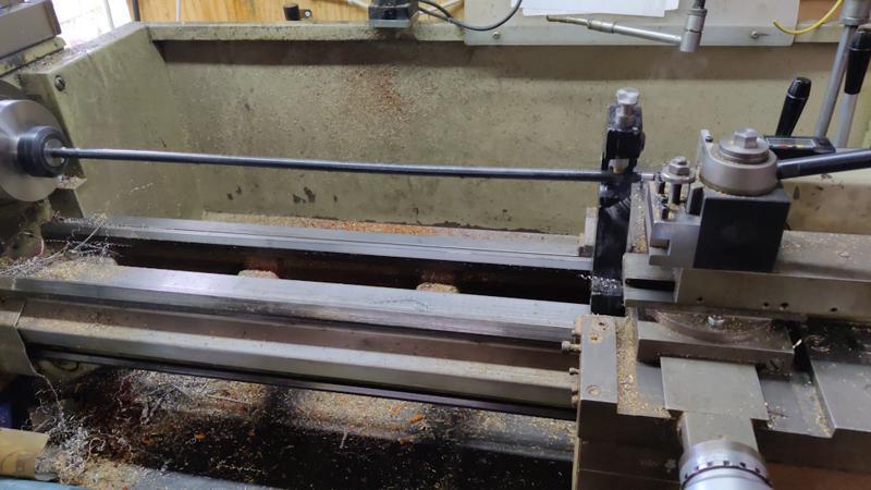
This was probably only the second or third time I'd used the travelling steady on my lathe but for a bar this length (and this far off straight: it wobbled all over the place when just supported at each end!), it was essential.

2024-12-29-01-travelling-steady-rough-turning_800.jpg


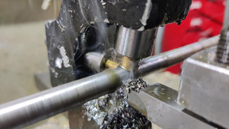
I started with a rough cut using a carbide insert tool following behind the steady. Close-up "action shot":

2024-12-29-02-close-up-of-rough-cut_800.jpg


The smoke you can see is coming from the cutting oil that I applied liberally during the pass. The carbide tool left a pretty awful finish on this horrible steel, so I did a second pass using a high-speed steel tool, this time with the steady following behind (and hence riding on the finished surface):

2024-12-29-03-smoothing-cut-with-hss-leading-steady_800.jpg


The finish was still far from perfect (I'm sure it would have been better if I had started with a bar that was somewhere near straight), but it'll serve the purpose.

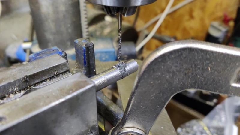
I used the pillar drill to cross drill the end of the bar with a 2 mm hole (which will hold onto the end of the element while it is wound):

2024-12-29-04-cross-drilling-2mm_800.jpg


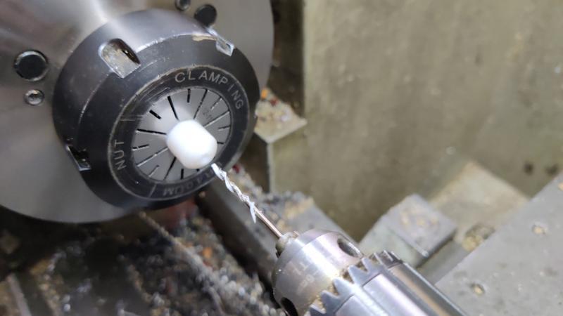
To feed the element smoothly, I found a bit of plastic in the drawer and turned it down to 12 mm diameter. From how easily it cut and gave a nice finish, I think it's probably acetal. Once turned down, I drilled as deep as I could go from one end with a 1.6 mm drill bit:

2024-12-29-05-drilling-1_6mm_800.jpg


Then flipped the part round and used a (much longer) 6 mm drill bit to go deep enough to meet the end of the 1.6 mm hole:

2024-12-29-06-drilling-6mm_800.jpg


The acetal part could then be held in a tool holder and used to smoothly feed the 1.4 mm diameter wire:

2024-12-29-07-feeding-wire_800.jpg


On the first go, I set the lathe up for a 1.4 mm pitch thread (so that the carriage moved 1.4 mm per turn, which should end up with the wire tightly bunched). Unfortunately, it ended up with a few lumps here and there:

2024-12-29-08-lumpy_800.jpg


I suspect that the wire is slightly over 1.4 mm diameter and hence every now and again it needed to self-correct slightly by layering up. For the second go, I changed the lathe to run on 1.5 mm pitch and it was much better:

2024-12-29-09-change-pitch_800.jpg


In this case, the "corrections" for diameter/pitch mismatch were just a very small gap now and then:

2024-12-29-10-close-up_800.jpg


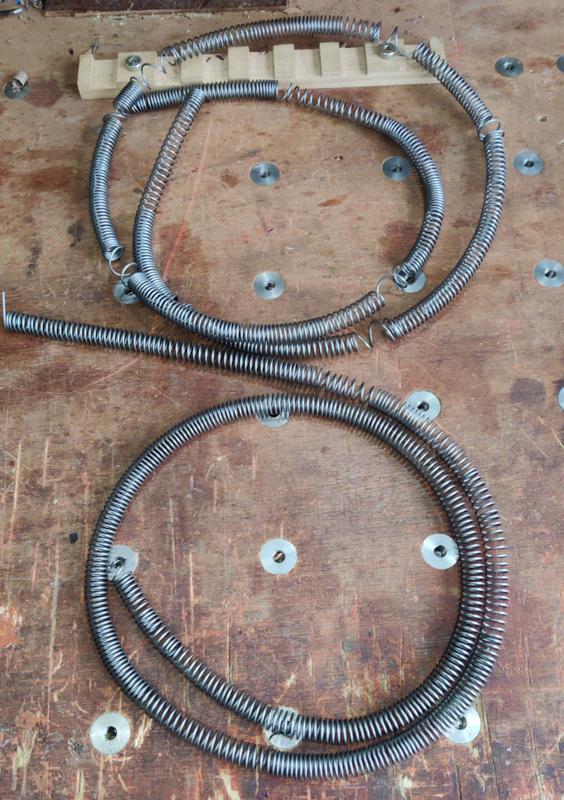
Here are the two coils next to one another (after stretching them a little by hand to separate the coils):

2024-12-29-11-comparing-coils_800.jpg


To sort out the lumpy bits of the first coil, I placed it back on the mandrel (held in the bench vice) and manipulated it with pliers and fingers until it was looking a lot neater:

2024-12-29-12-reworking-wonky-coil_800.jpg


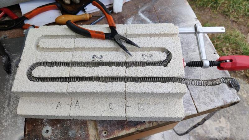
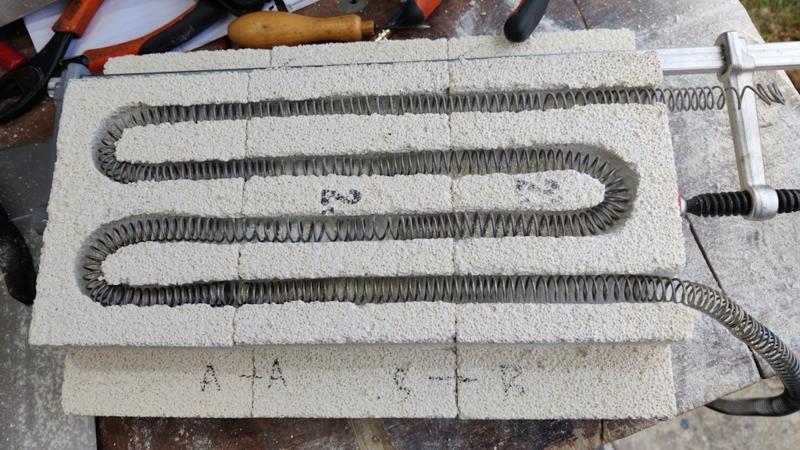
I could then do some investigation into coil sizing and position. The first coil ended up as 16 Ω; the second as 15 Ω. I've been designing the oven around a total resistance of 25 Ω or more (to suit the maximum continuous current rating of a UK three-pin plug). It's not the end of the world if it ends up more than that (as I can run it of a 16 A or 32 A plug if required as I have a suitable socket in the garage), but it'd be nice to run it off a normal plug if possible. With the two in series, the resistance will be 31 Ω; that would be fine as the current would be lower than with 25 Ω.

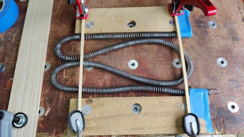
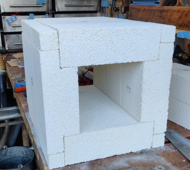
For 31 Ω I would use the two coils I've made, one in each side wall of the chamber. The size of the inside wall of the cavity with the initial brick layout is about 230 mm × 150 mm. To see what that would look like, I placed a couple of planing stops with their edges a bit under 150 mm apart. I used a pencil mark to show where the 230 mm dimension was and had a go at wrapping one of the coils back and forth in that space:

2024-12-29-13-wrapping-for-small-cavity_800.jpg


That seemed a bit dense to me: I'm not convinced I could lay that out and "mill" the slots for the the coils without the bricks breaking (as there wouldn't be much material left between the coils). If I go with this size cavity, I think I'll have to have heating elements in the side walls and the "ceiling" - that'll mean I could use coils half this length (and hence 8 Ω each) and the total would be 24 Ω, which would be close enough.

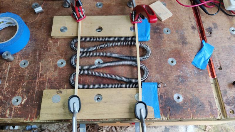
The alternative is to increase the depth of the cavity to 330 mm (by having three rows of bricks). To try that out, I clamped a piece of wood at the right distance as an end stop and had another go at the layout:

2024-12-29-14-wrapping-for-larger-cavity_800.jpg


That looks a lot more comfortable to me, so I think I'll go with that one. The disadvantage is that, if I try to use this chamber for casting (with the chamber lying on its back), the crucible will need to sit on top of something (perhaps an off-cut of fire brick?) to raise it up high enough to be able to grab hold of it. I think I can live with that.
 
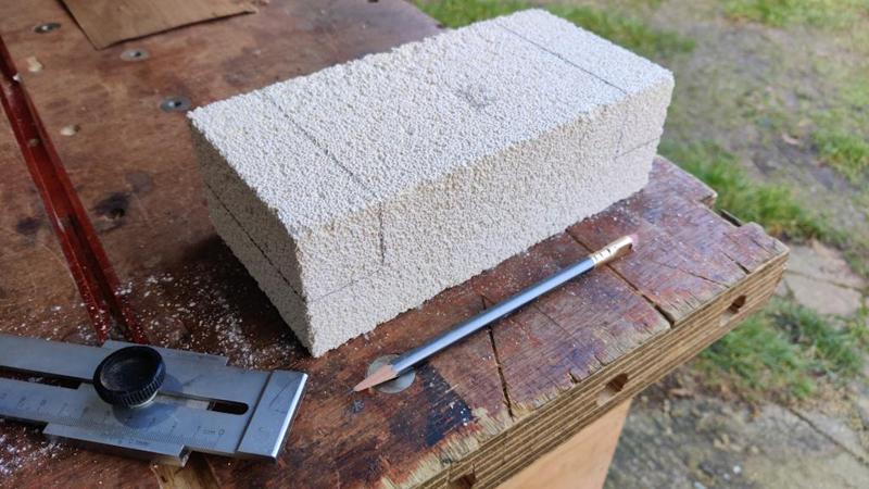
With the layout decided, I could get on with preparing some of the bricks. I started by using my edge distance gauge thing (one of my most frequently used tools) and a pencil to mark the bits that needed to be removed:

2024-12-29-15-marking-brick_800.jpg


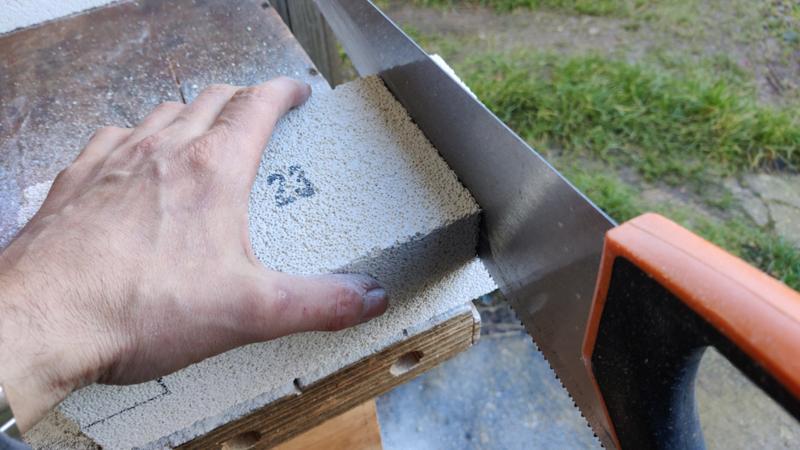
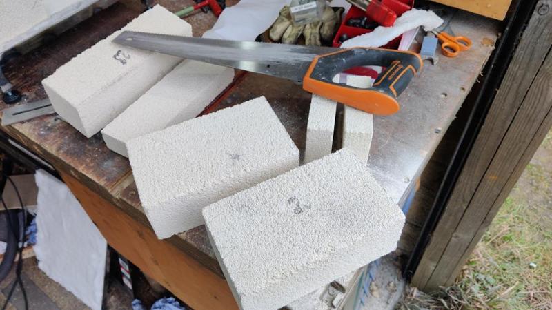
To cut the bricks, I used an old hard-point handsaw. It was phenomenally easy to cut (and to cut relatively straight): the handsaw powered through the brick with very little effort. On the first one, I clamped the brick down to the bench, but for the rest I just held it on the bench by hand. The friction between the brick and the bench is high and the force being applied by the saw is low, so it was very easy to do this without the brick slipping:

2024-12-29-16-sawing-brick_800.jpg


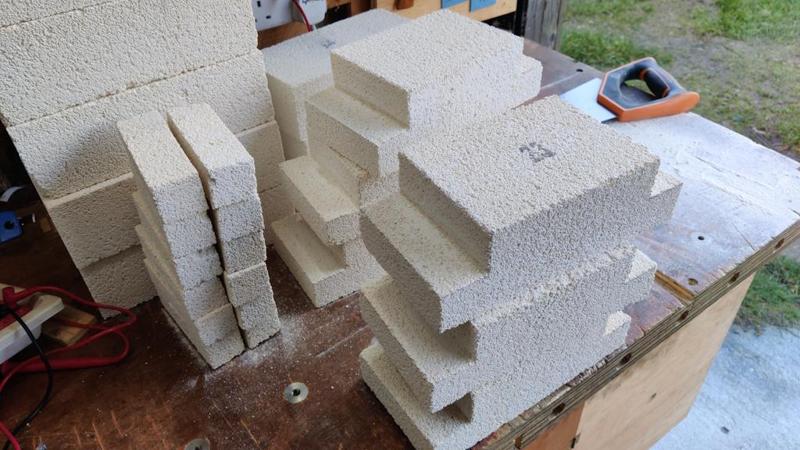
After lots of pencil sharpening and a bit of very quick sawing, I ended up with a pile of bricks that looked like this:

2024-12-29-17-lots-of-bricks_800.jpg


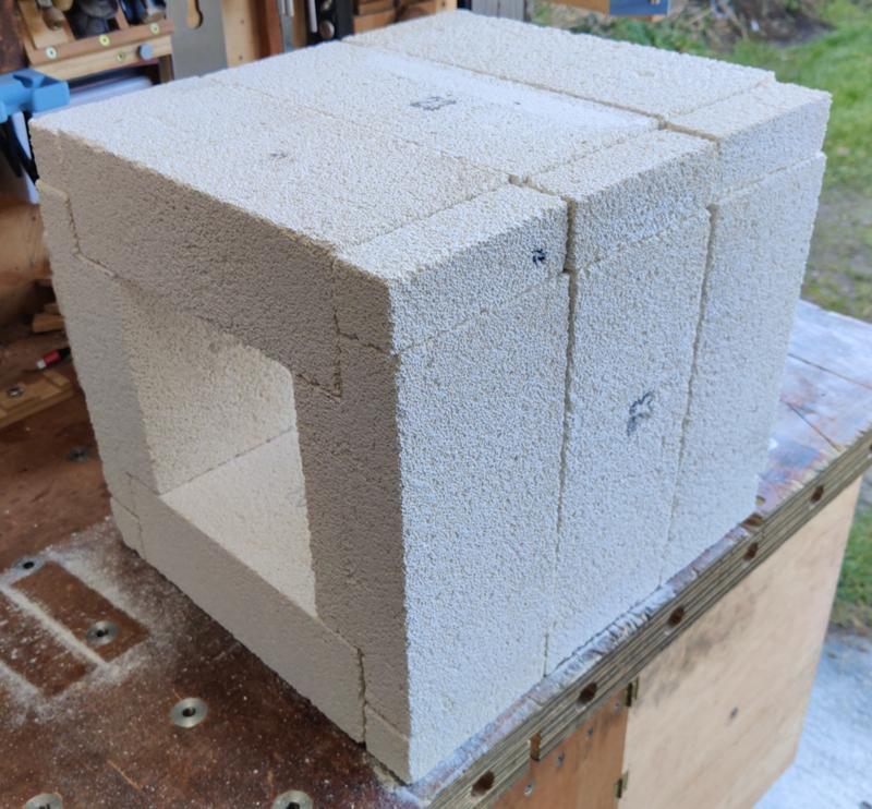
That was enough for a test assembly of the cavity:

2024-12-29-18-test-assembly_800.jpg


2024-12-29-19-test-assembly-2_800.jpg


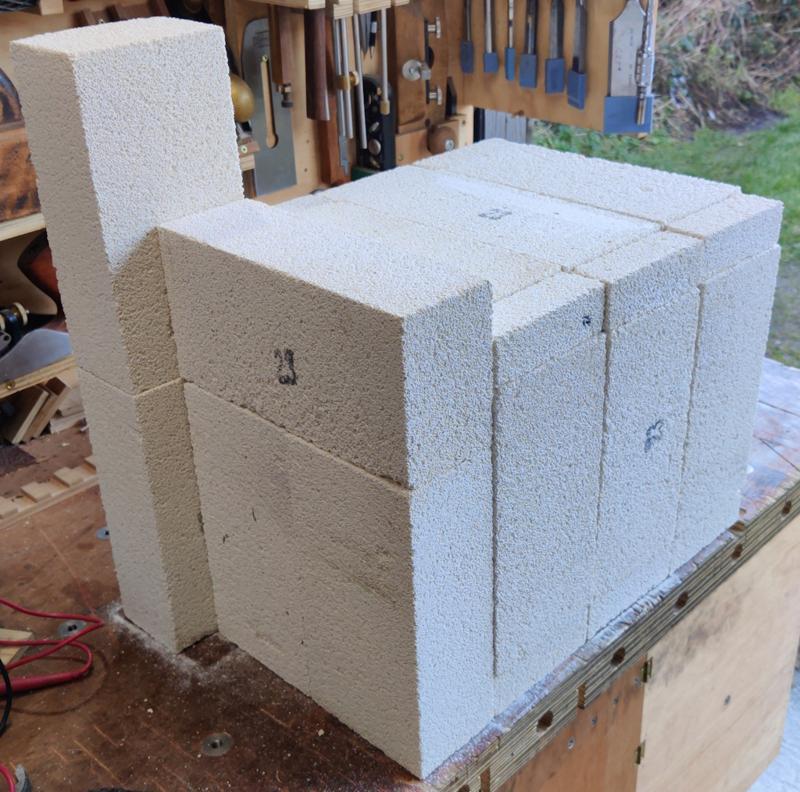
I also placed a few bricks on the end to help decide what to do for the door and the rear of the chamber:

2024-12-29-20-placed-end-bricks_800.jpg


They (obviously) won't look like that in the end; I haven't decided yet whether to just cut them off where they are at the moment or move the bottom bricks up a bit (so they're centred vertically). I'll probably go with the latter. Centred vertically will reduce the opportunities for heat escape, but has the disadvantage of using more cut bricks (as there will be a thin one top and bottom rather than just a thin one at the top).

The next job will be to start preparing the steel frame that will hold the bricks together. That'll involve a lot of angle grinder work to remove the mill scale on all the 20 mm × 20 mm × 3 mm angle iron I've got; I've got a bit of a headache at the moment so I can't face the noise (even with ear defenders on) of the grinder so I'll have a go at that tomorrow.
 
Al, I like your persistence with the lathe. If you didn't use it for something like this, when else would you have a low-risk chance to try out the travelling steady on a long thin workpiece like that?!

Re tomorrow's job, I think I remember a post about soaking hot rolled steel in acid to get rid of mill scale. I'll see if I can find it.

Edit - it was Richard T back in 2013
 
Al, I like your persistence with the lathe. If you didn't use it for something like this, when else would you have a low-risk chance to try out the travelling steady on a long thin workpiece like that?!

Re tomorrow's job, I think I remember a post about soaking hot rolled steel in acid to get rid of mill scale. I'll see if I can find it.

Edit - it was Richard T back in 2013
Thanks Andy. That's something I've done in the past (with citric acid). It does work well (although it needs a bit of a further brush to get rid of the last few bits). The disadvantage is that for long lengths you need to provide a long bath (or cut them down to size while still oily and scaly) and keep the "bath" warm for quite a while. In the summer, that's easy: a bit of guttering plugged at both ends and leave it in the sun. This time of year it's a bit more awkward and either way it takes quite a while for good results.

There's a picture of a sunny day gutter in the build log I wrote about making my bar clamps: https://www.cgtk.co.uk/woodwork/handtools/barclamps/blog/page5 - I still found the thicker mill scale needed a bit of attention once they came out of the citric acid, but it was definitely easier.

As it's a lot colder this time round, I think I'll just use a "non-woven preparation wheel" which is designed for the purpose and they work very well. Definitely a lot more effort than citric acid, but far, far easier and more pleasant than a flap disc or grinding wheel.


The disadvantage is that you need a variable speed grinder as they don't work well when run at full speed. The only variable speed grinder I've got is a battery one which goes through batteries like they're going out of fashion and is also a lot heavier than my mains powered one, but it works and it doesn't take too long with those preparation wheels.
 
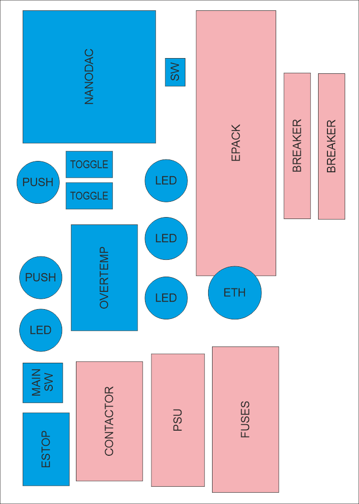
Before preparing the angle iron, I wanted to get an idea of roughly the right size for the control cabinet. The size isn't really critical (it's not going to be integrated into the chamber, so will be moved independently and hence if it's a bit oversize that's fine).

For this sort of job, I sometimes find that a simple drawing package (in this case CorelDRAW 2019) is the easiest option for playing with layouts (rather than using a fancy CAD package). I drew boxes representing the biggest dimension of each part (which won't be the same as the panel cut-out size) and played around with the layout until I found something that looked okay. I could then draw a box around it and see how big the front panel needed to be.

CabinetLayoutSketch.png


In that sketch, the things shaded blue will be mounted to the front of the cabinet (the cabinet door) and the things shaded pink will be mounted to the rear of the cabinet. By increasing the depth of the cabinet I could have overlapped them a lot more, but this layout gives me lots of spare space in case there's anything important I've forgotten.

I've tried to keep all the push buttons (including the emergency stop button) near the edge of the door (so they're closer to the strong angle iron rather than floating on the relatively thin sheet steel that will form the central portion). I've also tried to lay it all out relatively logically so power comes in on the right and the connections to the chamber are on the left. Thermocouple connections are on the left-hand side of the Nanodac controller, so these will be fairly close to where they come in through the side panel (but with enough slack in the cables to allow for the fact that the door will be hinged).

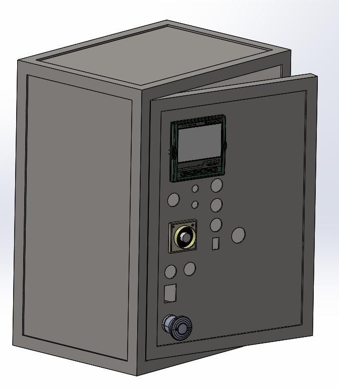
With the rough layout complete, I could quickly knock up a model of the cabinet in SolidWorks:

2024-12-31-01-cabinet-model_800.jpg


There are a lot of empty holes in that model as I don't have CAD models for the push buttons, LEDs, toggle switches and rocker switches I'll be using, but I do have datasheets for them, so the hole sizes should be correct. I haven't got as far as modelling the holes for thermocouple inputs, power output to the chamber, power input from the wall socket or any of the stuff that sits on the back panel, but the locations of those won't be so critical compared to the door components, so I might just figure them out as I go rather than trying to do a CAD model.

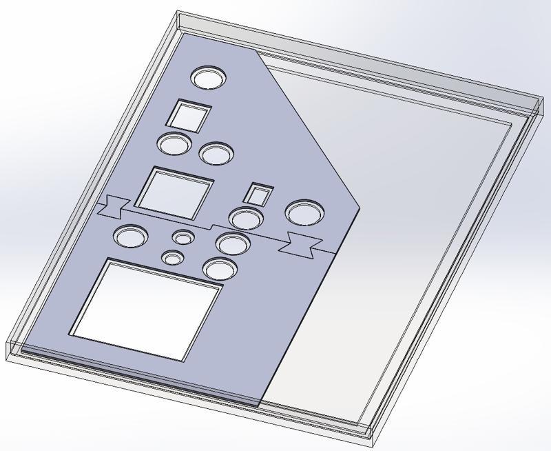
With the CAD model complete (ish), I could use the door model to create a new part (in an assembly context so I could refer to the door geometry):

2024-12-31-02-cabinet-template_800.jpg


This part is quite simple in that it's a 2 mm thick plate with holes that are 3 mm offset from the ones in the door. That part can be 3D-printed (in pieces, hence the butterfly joints, to allow for the limited size of the bed of my 3D printer).

With dimensions worked out, I could get on preparing the 20 mm × 20 mm × 3 mm angle iron. In the past (e.g. see here) I've used citric acid to remove the mill scale, but it takes quite a while even in warm weather and in December is likely to take even longer. I was too impatient for that so I just used an angle grinder. I started using a "non-woven preparation wheel", which works very well, but needs a variable speed angle grinder to run it relatively slowly. My only variable speed grinder is a cordless one and it's a lot heavier than my mains one, so after preparing the first length I switched to using a 40 grit flap disc in the mains grinder instead.

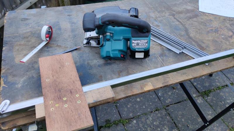
I'm sure anyone doing this professionally (where time is a bit more critical) would just clean up in the area around the welds (rather than cleaning all the mill scale off), but I find it much nicer to work with the fully cleaned steel so I got rid of all the scale. I then used my wonderful metal cutting circular saw with a simple cross-cutting jig (which had its fence cut to length using the saw so the end of the fence can be used to align it with a mark) to cut the angle down to length for the various parts.

2024-12-31-03-cutting-angle-to-length_800.jpg


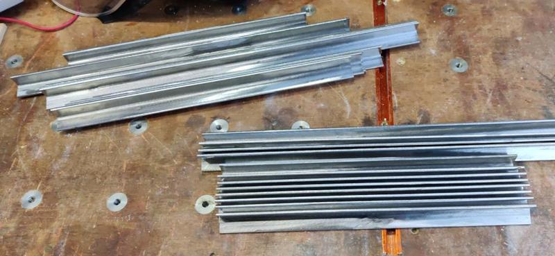
Believe it or not, this is about 9 metres of angle iron (comprising all the pieces for the chamber body frame and the pieces for the front, back and door of the control cabinet):

2024-12-31-04-nine-metres_800.jpg


I've got 3 metres left, which I don't think will be quite enough to do the chamber door and the cabinet sides, but I've got various bits of flat bar and some wider angle so I'm sure I'll be able to figure something out.

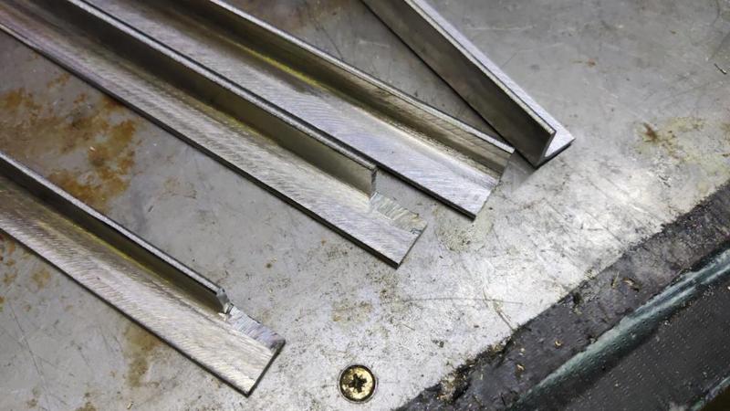
To make the angles into frames, I cut a little bit out of the corners:

2024-12-31-05-corner-cutouts_800.jpg


After a bit of a clean up of those corner cut-outs, I assembled the control cabinet frames, first tacking one point on one corner:

2024-12-31-06-tacking-first-corner_800.jpg


Then doing the same point on the other three corners:

2024-12-31-07-tacked-first-frame_800.jpg


After checking that the frame was square, I tacked together the other two frames for the control cabinet and could then check that the door frame fits inside the outer frame:

2024-12-31-08-door-fits-inside_800.jpg


Each frame then got a couple of extra tack welds in each corner and then I checked for square again:

2024-12-31-09-two-more-tacks_800.jpg


Finally, I could weld three seams together, which should be enough I think:

2024-12-31-10-welding-edges_800.jpg


The door no longer fits in the aperture because of how the weld beads stick up, but that'll get sorted when I grind the beads back.

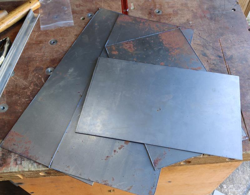
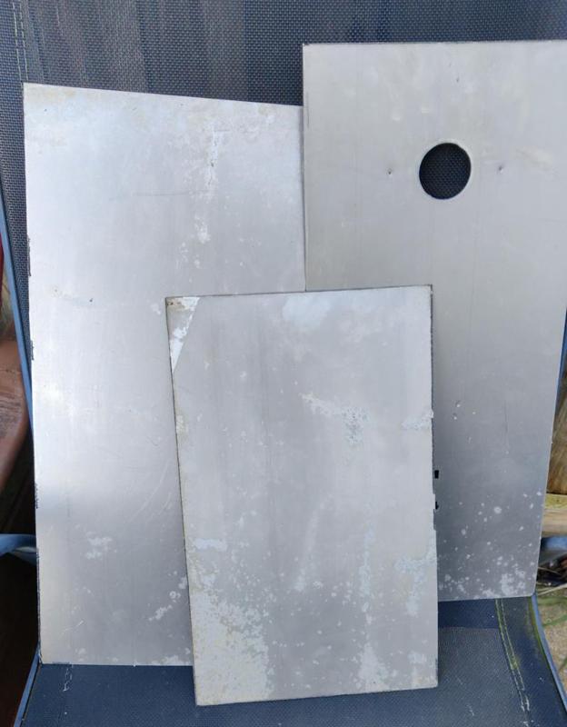
For the inserts inside the door, I've got a couple of sheets of 1.2 mm thick steel that has been sitting in my shed. Unfortunately, the steel has suffered a bit from the less-than-ideal storage conditions and is rather rusty. One piece was mostly covered in plastic and seems a lot better, but I thought I'd start with the rusty one and see how it goes. Hopefully the rust can be cleaned up with a wire brush or flap disc; I'll probably have to paint the cabinet before final assembly to protect it for when its in storage (I hate painting).

To cut the sheet up, I used one of the frames to support the sheet as it hung over the end of my bench and then used a piece of angle iron as a straight edge. I could then use the plasma cutter to split off the door insert:

2024-12-31-11-straight-cut-rusty-steel_800.jpg


I tend to use my metal-cutting circular saw for straight cuts like this as it's fast and leaves a nice finish, but the plasma cutter is quieter and I was planning to use it for some curved and internal cuts so I figured I could use it for the straight cuts too. It left a reasonably nice finish (and only took a couple of seconds to do the 300 mm long cut):

2024-12-31-12-clean-cut_800.jpg


The rusty panel fits inside the door with a few millimetres of gap all the way round. Once it's fully prepared (with the rust sorted out and the holes for the control gear cut in it), the plan is to put a few short welds around the perimeter to hold it in place.

2024-12-31-13-fits-in-door_800.jpg


The nice thing about using this rusty bit of steel is that it means I've got more available for practice. If I make a mess of anything on the first go, I won't mind chucking this piece away and cutting some more out. If it takes more than about three goes to get it right, I'll have to break into the supply of non-rusty steel and that'll make everything easier later!

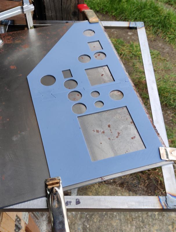
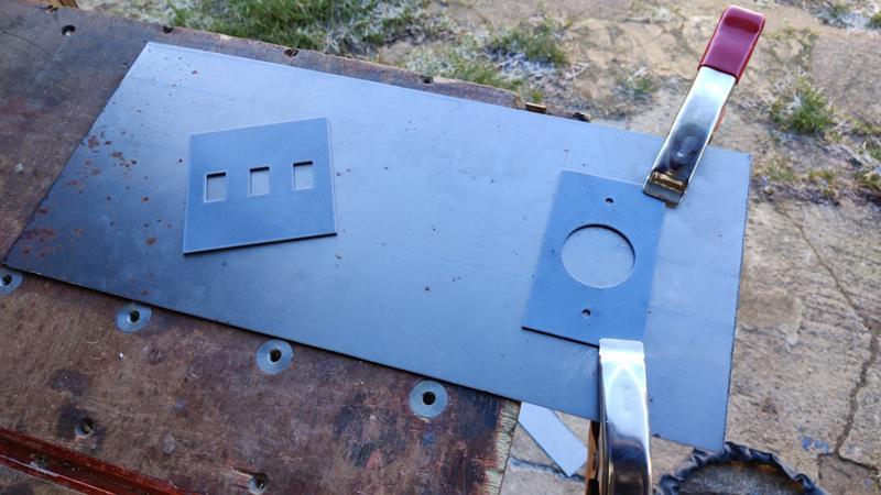
That plasma cutting template that I showed earlier had finished printing (it took about 8 hours in total) and I held it in place with a couple of clamps, using one of the frames to support the steel again so it could hang off the edge of the bench:

2024-12-31-14-laying-printed-template-in-place_800.jpg


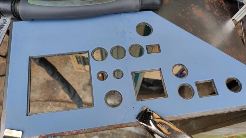
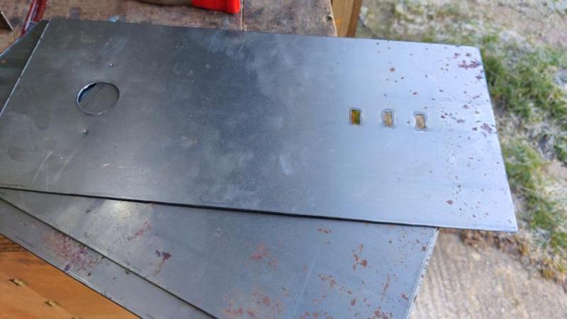
About a minute later, all the holes were cut out - the plasma cutter really is fast!

2024-12-31-15-plasma-cut_800.jpg


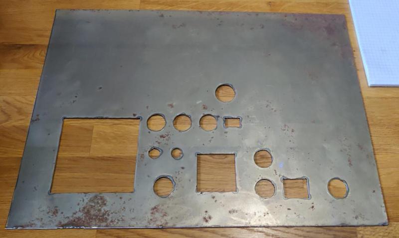
Some of the holes (especially the smaller ones for the toggle switches) are a bit shabby, but all things considered I was very happy with the finish:

2024-12-31-16-ready-for-test-fit_800.jpg


I did a test fit of a few of the things that go in those holes and most were just too big to go in easily. Most would have gone in with a bit of persuasion I think, but I don't want to do that. I'm happy with that fit as I can tweak it with hand files; it won't take much filing to get them to the right size and it'll allow me to deal with some of the shabbier bits of the cut.
 
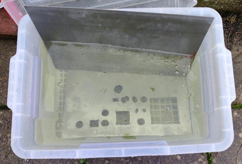
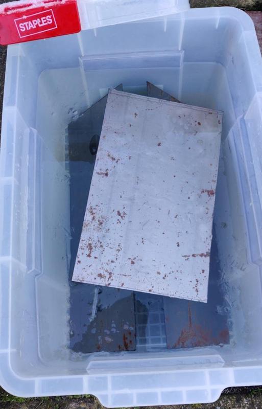
I've lost my mojo a bit at the moment and I'm not managing to do much each day. Not sure why; these things happen now and again. Anyway I am managing the odd bit. The sheets I prepared yesterday went into a citric acid bath last night in the optimistic hope that it would help with the rust and save a bit of wire brush work:

2025-01-01-01-citric-acid-bath_800.jpg


They've been in there for about 18 hours so far without much happening, but I'm not that surprised as it's relatively cold outside and that definitely affects how well the acid works. If there isn't much progress in the next day or so I'll probably give up and just deal with it with a wire brush.

What I did manage to do today was make a tiny bit more progress with the control cabinet frame. I drilled some 11 mm holes in the ends of the two outer frames:

2025-01-01-02-drilling-11mm-holes_800.jpg


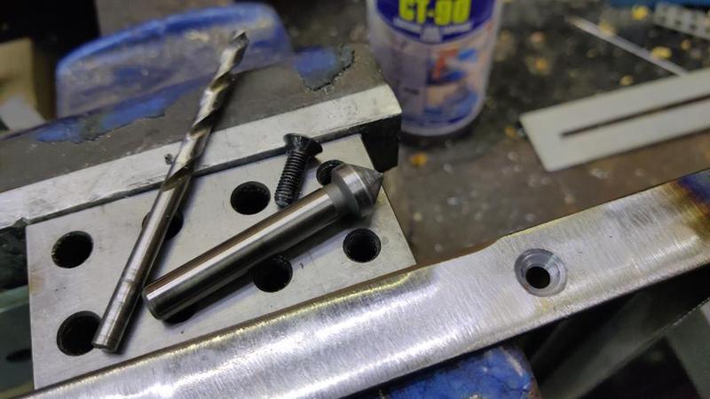
The frames are two big for the pillar drill so I used a cordless drill instead. I also drilled the first couple of what will end up being quite a few countersunk holes for earth studs so that I can make sure every bit of metalwork is properly earthed:

2025-01-01-03-drilling-earth-holes_800.jpg


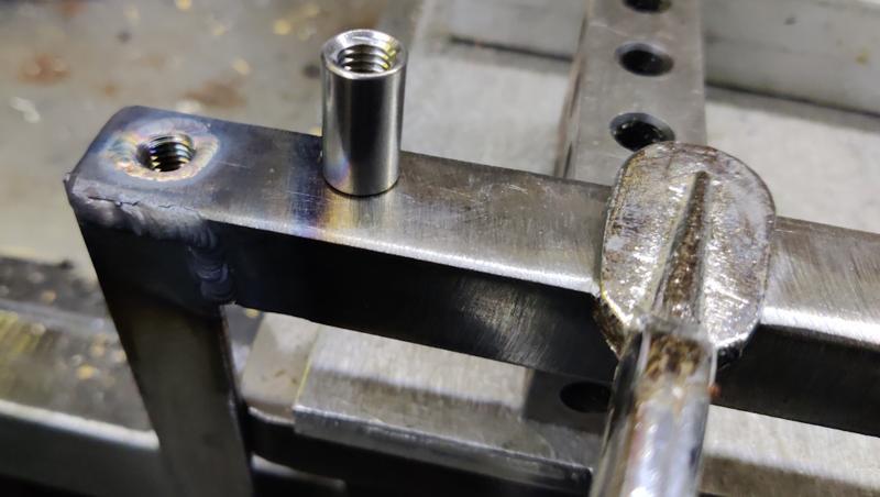
The 11 mm holes were for some M8 weld nuts (sold as cylindrical coupling nuts), which are a tight fit (needing gentle mallet-based persuasion) in the 11 mm holes. They get whacked into place and then welded the lazy way autogenously (i.e. without filler) in place.

2025-01-01-04-welding-weld-nuts_800.jpg


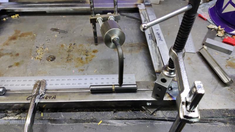
I decided I'd then have a go at my first bullet hinge. I'd never used these before and I was quite concerned that the inevitable movement that happens during welding would result in the two hinges having misaligned axes and hence the door not hinging properly.

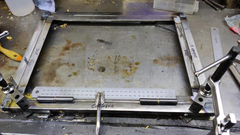
To try to align the hinges, I clamped the frame and the door in place with some feeler gauge stock giving a gap all the way round (even at the top and bottom and a bit wider at the opening edge vs the hinge edge). I then clamped a steel rule to the door at what seemed like the right distance from the edge to try to get the hinges aligned and parallel with the edge.

2025-01-01-05-aligning-bullet-hinges_800.jpg


I couldn't think of a good way of clamping the hinges in place (partly because I'd clamped the door frame in place too far from the edge of my bench to give a good choice of clamps) so I just used a Welder's Third Hand to keep it in place...

2025-01-01-06-third-hand_800.jpg


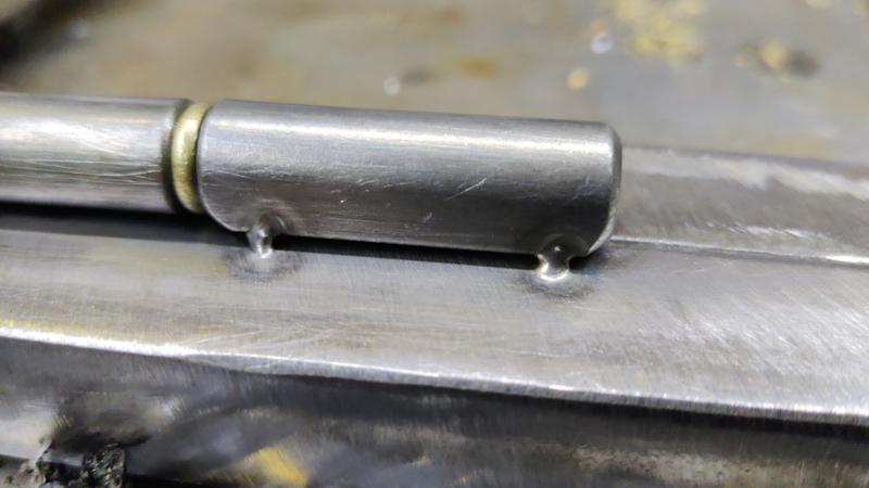
... while applying a couple of tack welds to each piece:

2025-01-01-07-tack-welds_800.jpg


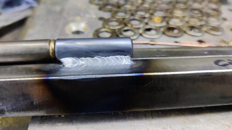
After releasing all the clamps, a quick check showed that the hinges still worked as expected so I welded all the way along each joint:

2025-01-01-08-full-weld_800.jpg


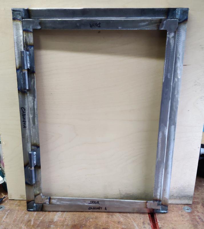
Once I'd had some lunch and let it cool down, I could try it out and it works... not perfectly, but much better than I expected.

2025-01-01-09-door-assembly_800.jpg


The loose bullet hinges slide apart extremely easily. In theory, it should be similarly easy to lift the door off the hinges but they're much too stiff for that now (due, presumably, to slight misalignment). However, a few taps with a mallet separates them, which I think is good enough.

The door opens easily (and closes again!) but doesn't fully close naturally. If you lean it back so the door swings shut the door will stop with this much of a gap:

2025-01-01-10-not-fully-closed_800.jpg


Light pressure overcomes that last bit of springiness and the door can be shut, so with a latch of some sort (I haven't even started to think about that yet!) it should shut fine:

2025-01-01-11-pushed-shut_800.jpg


The maximum amount you can open the door is, as you'd expect, the point where the two bits of angle iron hit each other:

2025-01-01-12-maximum-open-extent_800.jpg


Overall I'm really pleased with that as my first attempt to weld a hinge in place. It would be nice to know what I should do differently to get the hinges to align perfectly (for easier removal of the door), but they work remarkably well as hinges given the fact they can't be perfectly aligned (or else it would be easy to remove the door).
 
Well you get a lot done for a man who's lost his mojo. Nice work.
 
Looks good.
This is work that I can understand having welded frames and gates years ago.

Thanks. I do quite enjoy welding (but definitely not all the grinding / cutting that leads up to it!). I still find it frankly astonishing that I can hold something the size of a fat marker pen in my hand and use it to melt steel and then push that molten steel around.

Well you get a lot done for a man who's lost his mojo. Nice work.

Thanks Adrian. Those welding jobs were probably only a couple of hours work total (including all the drilling, clamping etc). I've had a slightly more productive morning this morning, so perhaps things are improving a little. We shall see.
 
Thanks. I do quite enjoy welding (but definitely not all the grinding / cutting that leads up to it!). I still find it frankly astonishing that I can hold something the size of a fat marker pen in my hand and use it to melt steel and then push that molten steel around.

I would spend a good 20 minutes on scrap before drawing a good bead and no bird-crap.
 
I would spend a good 20 minutes on scrap before drawing a good bead and no bird-crap.

If I try arc (stick) welding, it takes me a lot longer than that, but I'm not too bad with TIG (especially with a foot pedal, which gives a lot more control). One day I'd like to get a MIG welder (just because it's so much faster), but I do like the cleanliness of TIG: it's nice to not have to worry about spatter etc so I can do it in a small area of the workshop rather than having to clear lots of space.
 
On inspecting the steel sheets (in their citric acid bath) this morning, they still looked slightly rusty, but I pulled them out and gave them a quick wipe with a tissue and the rust came off really easily. At this point, you have to work fast as it's astonishing how quickly they'll start to tarnish once they're out of the acid bath.

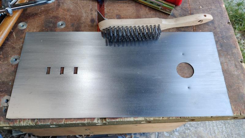
I wiped them over with some paper towel and then attacked them with a wire brush. I could have oiled them but I knew I was going to weld them almost immediately so I would have had to clean the oil off again very soon. The wire brush was quite a good work-out for the start of the day anyway considering how much the temperature had dropped overnight.

2025-01-02-01-wire-brushed_800.jpg


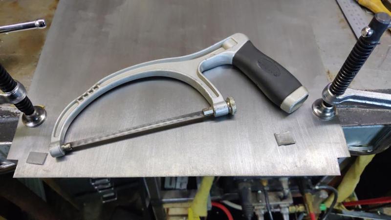
The insert for the back of the control cabinet needed a couple of little cut-outs (because of the weld nuts that I fitted yesterday). I cut out the pockets with a junior hacksaw (as it has finer teeth than my big hacksaw and hence is better for cutting thin sheet). I probably wrecked the blade in the process as it took my an embarrassing amount of time to remember that it was set up (as they usually are) to cut on the push stroke and I've been doing a lot of work with Japanese woodwork pull saws recently! Nevertheless, it did the job quite quickly:

2025-01-02-02-junior-hacksaw_800.jpg


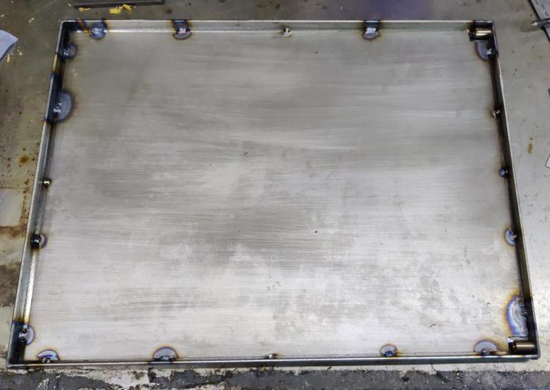
I could then place the sheet into the back panel and do a few tack welds all the way round. I'd been doing quite well at welding yesterday but, while it went fine on these joints, I dipped the tungsten in the weld pool quite a few times today, making me glad I had quite a lot of them ready ground so I could quickly swap them out after each mistake. Anyway, it got done:

2025-01-02-03-tack-welded-back_800.jpg


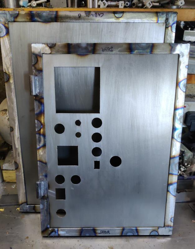
As did the door insert, which had a somewhat higher density of tacks along the left-hand edge as that's where all the controls are and hence it'll see a bit more force from push buttons being pressed:

2025-01-02-04-front-sheet-fitted_800.jpg


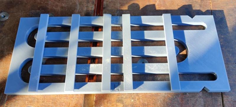
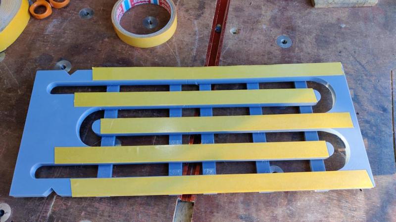
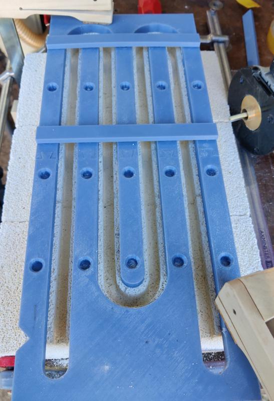
Overnight, I'd 3D-printed a guide (with a 17 mm wide slot) to help with preparing the blocks for the heating element:

2025-01-02-05-printed-guide_800.jpg


The plan with this is to have the heating element captive (by having an undercut slot). I'm not especially confident of how that will work as the fire bricks are incredibly brittle and it wouldn't take much for the retaining lip to break.

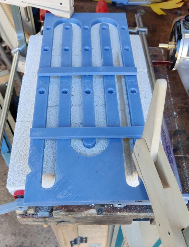
To hold the guide in place, I expected (correctly as it turned out) to need to use clamps and such-like. The little cross-pieces you can see fitted to the guide are there to hold the fingers in place while routing grooves in other areas (but they obviously need to be removed when the router is in that area). In a fit of optimism, I decided to try some double-sided tape just on the off-chance it would stick to the fire bricks:

2025-01-02-06-optimistic-tape_800.jpg


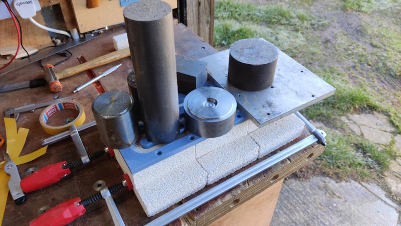
After removing the backing paper, I placed the frame on the bricks and covered it in heavy bits of steel to hold it in place.

2025-01-02-07-weights_800.jpg


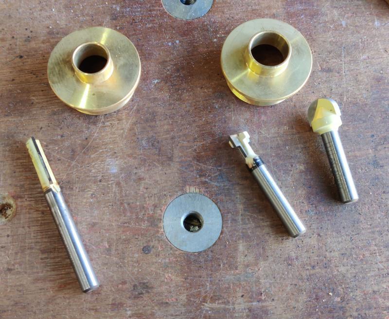
Once it had been left for 10 minutes or so, I removed the weights. It took the lightest of touches to remove the guide from the bricks, so the tape didn't work. Not a great surprise, but it was worth a try. These are the router bits and guide bushes I intended to use:

2025-01-02-08-router-bits_800.jpg


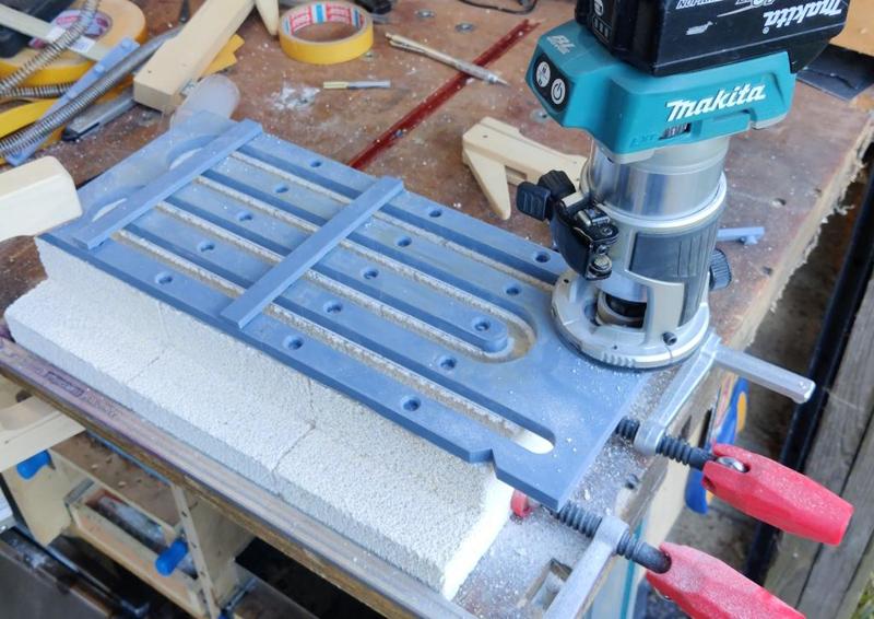
In the end I didn't bother with the little key-hole cutter (which was only intended to be used for a light undercut to deal with the area where the cove (?) bit didn't cut). The 6.35 mm (1/4") straight bit was used with a 14 mm guide bush, which hence allowed it to move 3 mm in the 17 mm wide slot, producing a 9.35 mm wide opening. The cove bit is 12.7 mm (1/2") diameter and is used with a 16 mm guide bush, producing a 13.7 mm opening. In practise of course, none of those dimensions will be anywhere near that precise, but that was the aim. For reference, the element coil is a little over 13 mm diameter.

Routing out the groove was a bit of a plod as I had to keep moving clamps and cross-bars. For the first pass (with the straight cutter), I fitted the vacuum attachment to the little trim router, which worked remarkably well at catching most of the dust produced (I still had the respirator on just in case). This photo shows how it looked part-way through routing the slot...

2025-01-02-09-part-way-routed_800.jpg


... and this one shows the straight slot finished:

2025-01-02-10-slot-routed_800.jpg


For the work with the cove bit, I got rid of the vacuum attachment (but kept the respirator on). That was partly because there would be less dust produced in this step, but mostly because I couldn't remove the router from the slot when I was moving the cross-bars around and the vacuum hose would have been a bit unwieldy (with it attached, I couldn't have just left the router sitting in place while moving the bars around as the weight of the vacuum hose would have pulled the cutter straight through the fire brick).

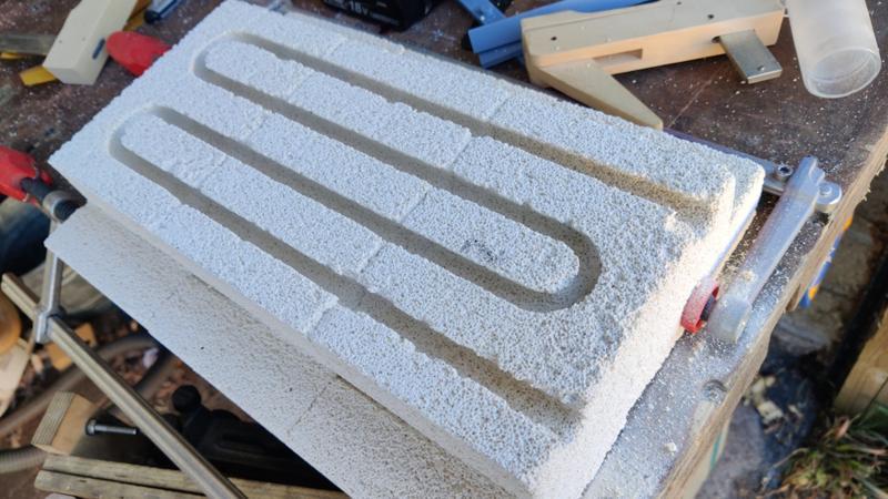
Anyway, it didn't take that long to go all the way around the groove. There were quite a few little breaks, resulting in a rather shabby edge, but it worked better than I thought it would (I didn't have very high hopes for this process!)

2025-01-02-11-fully-routed_800.jpg


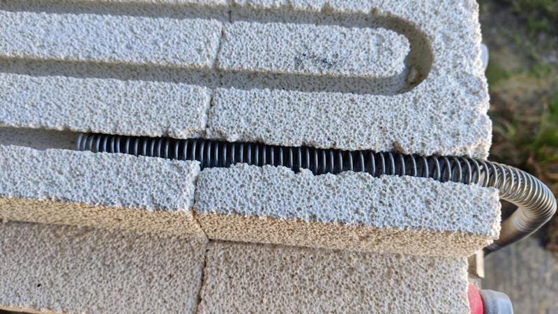
I haven't tried feeding the wire all the way round yet (as it still needs stretching out a little more), but I did a quick test fit and it went in relatively easily:

2025-01-02-12-test-fit_800.jpg
 
Fascinating.
I can imagine that there must have been some interesting dust coming off those blocks while routing.
 
Must have been very nerve racking cutting the channels ! What type of welder do you use? I must not have been paying attention.
Did you do a test run on spare bricks to figure out what rpm for the cutter and the feed rate?
 
Fascinating.
I can imagine that there must have been some interesting dust coming off those blocks while routing.
I'm sure it wasn't something you'd want to breathe in (hence the respirator). The vacuum on the little trim router worked really well on the first pass though (surprising given the guide bush limiting the air/dust path).

Must have been very nerve racking cutting the channels ! What type of welder do you use? I must not have been paying attention.

As you've already spotted: TIG. I only have TIG and stick/arc welders but I like the fume & spatter free nature of TIG.

Did you do a test run on spare bricks to figure out what rpm for the cutter and the feed rate?

No. I ran the cutter at the minimum speed the router would do (mainly so it was less of screaming monster!) and just fed it gradually without thinking about it too much.

I've got plenty of spare bricks and the preparation I'd done by this point (cutting the rebates in the corners) only took a couple of minutes (if that), so I worked on the premise that if this slot failed I'd grab some more bricks & try again.
 
I started the afternoon with a repeat of the last job of the morning: routing out the slots in a second set of bricks (after cutting the rebate in one as I'd dropped one of the set and it had got damaged):

2025-01-02-13-rinse-and-repeat_800.jpg


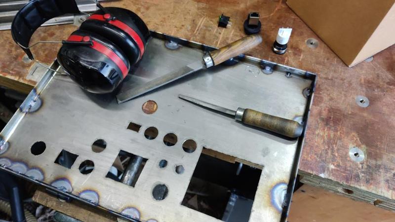
With the grooves finished I was very happy to be able to put all the routing paraphernalia away and get on with another job. It was perhaps a little unusual that I didn't need ear defenders for the electric router (as it was running on its lowest speed setting and cutting something relatively soft) but I did need ear defenders for the hand tool job that followed it: hand filing the openings in the door to get a good fit for the various things that will go in.

2025-01-02-14-noisy-filing_800.jpg


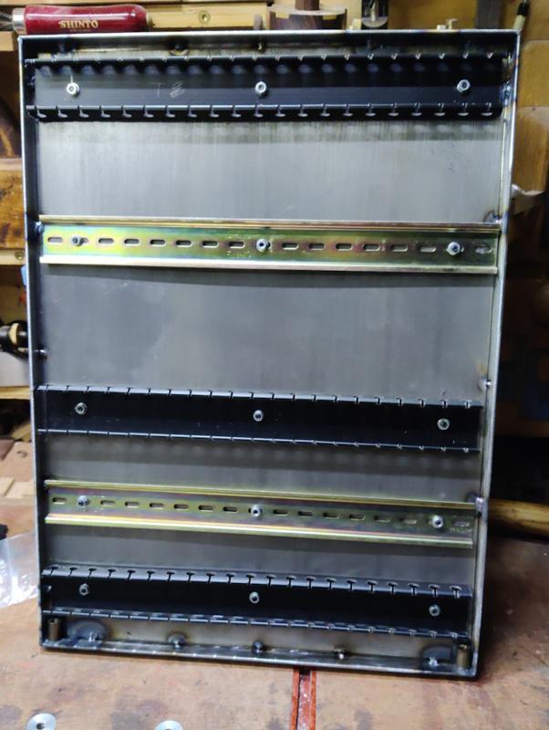
With the holes suitably fettled I moved onto the back panel and laid out the trunking and DIN rail to suit the various bits that were going to be fitted there:

2025-01-02-16-rear-panel-layout_800.jpg


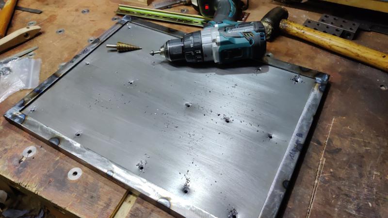
I could then drill the holes in the back of the panel. My original plan had been to drill these with a 4 mm step drill and then countersink them for M4 countersunk screws. I did that...

2025-01-02-17-drilling-holes_800.jpg


... but (as I should have realised) the metal was too thin for a good countersink so once I'd deburred the inside surface, I ended up with an oversize hole with not much countersink left. To resolve that, I fitted the various bits and pieces using cap screws and penny washers on the outside and with nuts and normal washers on the inside. In a surprising rebuff to Murphy, I had exactly the right number of M4 penny washers for the job!

2025-01-02-18-fitting-din-rail-and-trunking_800.jpg


Finally, I could retreat to the relative warmth of the dining room and fit all the various bits and bobs into the door panel and get an idea of what it will look like:

2025-01-02-15-door-test-fit_800.jpg


Now that I can fit stuff to the front and back of the cabinet, I can work out the required depth and cut the last four bits of cabinet angle iron to length. Hopefully tomorrow I'll get the cabinet frame welded together and start preparing the sheets for the sides, top and bottom.
 
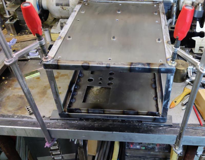
The first job this morning was welding the control cabinet frame together. I cut four 180 mm lengths of angle iron and tacked them to the door frame. I then clamped the top frame on and tack welded that in place:

2025-01-03-01-welding-frame-together-1_800.jpg


After checking how square it was (not entirely, but close enough: I rarely manage perfectly square welded constructions when there are this many joints involved), I could finish the various welds off. This was a lot more awkward than previous welds due to the size of the object. This orientation in particular involved standing up to weld, which isn't the end of the world, but is definitely more difficult than doing it seated:

2025-01-03-02-welding-frame-together-2_800.jpg


This orientation wasn't too bad:

2025-01-03-03-welding-frame-together-3_800.jpg


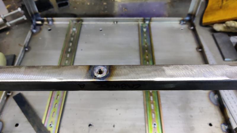
While I had the gas on and the welder powered, I drilled a 10 mm hole in the cabinet frame and set an M6 weld nut into the hole:

2025-01-03-04-m6-latch-nut_800.jpg


That'll be used for the door latch.

The last big job to sort out on the control cabinet (if you ignore the huge job that'll be wiring it all up!) was to cut out the sheets for the sides, top and bottom. Most of these came out of the same sheet of rusty 1.2 mm sheet, but I didn't have quite enough (without breaking into a new piece) and the bottom of the cabinet won't need much strength, so I just used an off-cut of (not rusty this time!) 0.8 mm sheet:

2025-01-03-05-panel-sheets_800.jpg


The 3D printer had again been active this morning preparing a couple of extra templates for plasma cutting:

2025-01-03-06-more-templates_800.jpg


The cutter quickly roughed out the holes (note that I just marked the positions of the two smallest holes as I figured they'd be easier to drill):

2025-01-03-07-plasma-cutting-done_800.jpg


There will still be another hole in the side panel (for the wires from the door interlock), but that's likely to be circular so I'll just drill that as and when I've decided where it needs to go and what type of connector to use (probably a 3-pin DIN connector as I think I have some somewhere).

The rusty pieces then went into the citric acid bath (after I'd broken up the ice on the top layer). Hopefully it'll still work despite being even colder now than it was when I did the first two pieces.

2025-01-03-08-citric-bath_800.jpg


There's not much more I can do with the cabinet until the rust has gone and those panels can be welded in place. I don't want to start wiring it up yet as I'd be worried about welding the panels in with all the wires and plastic parts in place (even ignoring the fact they'd probably get in the way). However, once they're welded in then I can bring the cabinet into the house and wire it up in the warmth! It'll all have to come out again when I paint the cabinet (a job I detest), but that's not going to happen for quite a while yet.
 
I decided to check the citric bath after lunch and, while the sheets still looked rusty, the rust wiped off with a paper towel, so that was a bit of a result. I think I'd been remembering how long it took to remove mill scale with citric acid; that's a lot thicker than this very light dusting of rust. After wiping with a paper towel, this is what the sheets looked like:

2025-01-03-09-wiped-after-citric-bath_800.jpg


As before, they got an aggressive brushing with a wire brush (which was quite welcome exercise to warm up in the 2°C ambient):

2025-01-03-10-brushed_800.jpg


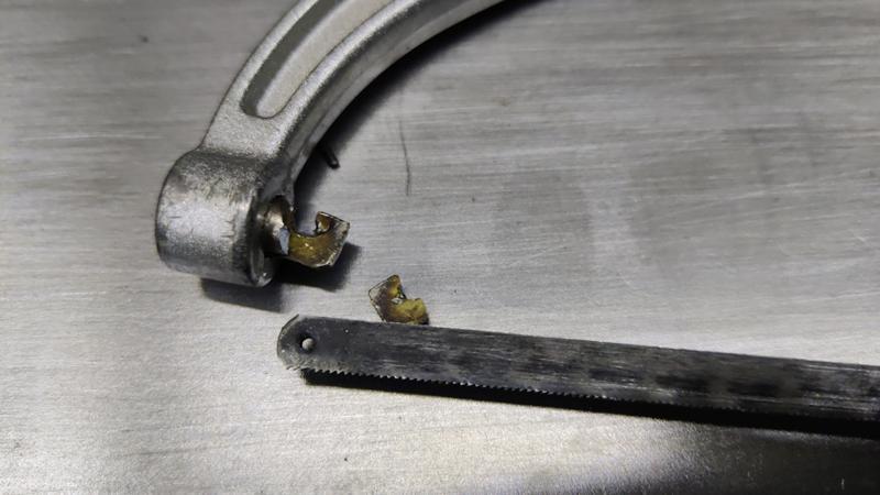
As before, I cut out the corners where necessary, firstly using my junior hacksaw until, sadly, it snapped on the penultimate cut:

2025-01-03-11-broken-hacksaw_800.jpg


I did the last one with the big hacksaw. There was then a lot of tack welding and a lot of cursing. This was probably some of my worst welding ever: I'd left a gap between the sheets so that I could weld them to the angle iron. I should have left a much, much bigger gap as trying to weld them to the angle iron without melting the neighbouring sheet proved to be extremely difficult, especially given that the frame was getting more and more closed up as a result of all the sheets on the sides!

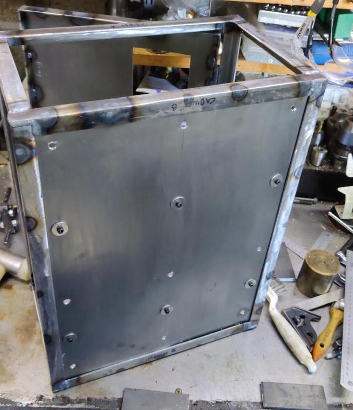
Anyway, I got it done (no photos of the process) and also fitted another M6 weld nut into the door (for the other part of the latch). I don't think there's any more welding to do on the control cabinet now, so I could fit the (cheap and a bit nasty, but they'll do) feet into the threaded holes in the bottom.

2025-01-03-12-all-done-with-feet_800.jpg


There are still some more holes to drill in the two sides, but some of those need a bit of thinking about locations so I'll probably do them after I've done some of the wiring.

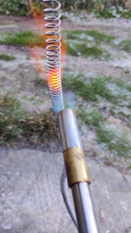
I need to get on with the chamber itself soon, although progress might be a bit slow given how wet the next few days are forecast to be (some of the jobs I have to do need to be done outside really). One thing I did get done today was to stretch out the element coils a bit more. A member of the MIG welding forum had made a couple of comments about the elements that proved very useful. One was that the wire work hardens and benefits from being heated up with a propane torch after coiling to allow it to be manipulated more easily. The other comment was that when it's hot, it sags under its own weight. That gave me a simple idea for how to stretch the coils out: hold the element vertically and apply heat with a propane torch. As it starts to glow red, that bit of element stretches (under the weight of the rest of the coil) and you can control the amount of stretch by withdrawing the propane torch just before it gets to the expansion you want:

2025-01-03-13-stretching-with-heat_800.jpg


That was quick and worked fairly well, although there were a couple of areas where I hadn't stretched the coils at all and, as a result of the turns touching each other, those areas required more heat and the areas either side thus stretched a bit more than I wanted. Being annealed, it was quite easy to push those areas roughly back together: I'm not aiming for perfectly uniform spacing or anything.

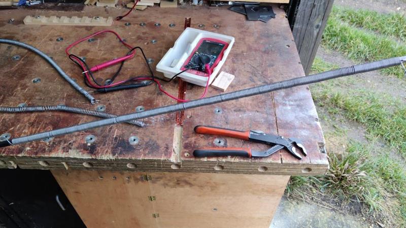
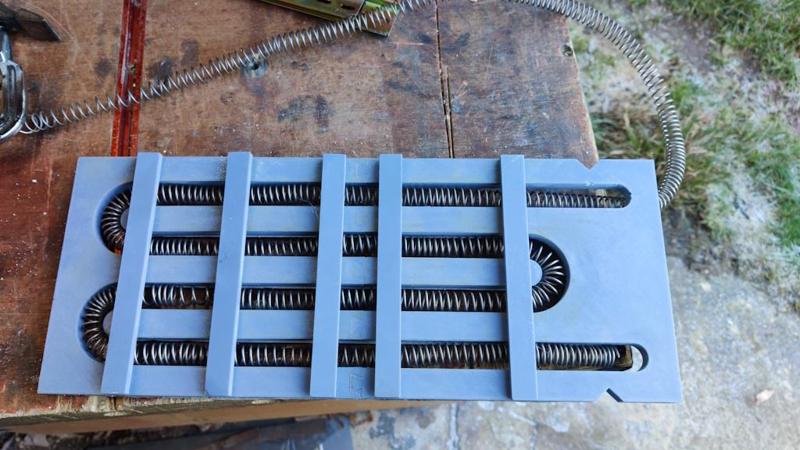
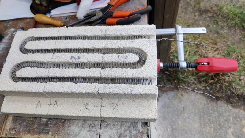
I used the routing template as a convenient way of laying the coils out to measure the resistance I'll end up with:

2025-01-03-14-testing-resistance_800.jpg


According to my cheap and simple multimeter, that gave each element as about 10 Ω, which (when in series) will result in up to 12.5 A flowing through the coil (assuming I don't use the thyristor pack to reduce that). That's slightly higher than I was aiming for, but good enough if I run it off a 16 A plug.

I'll probably bring the (decent, Fluke) multimeter I use at work home sometime during the week so I can double check the resistance using something I trust a bit more.
 
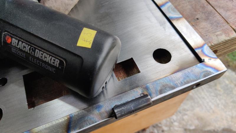
Today was another fairly slow day, but I got a few little jobs done. I'd noticed a bit of scarring on the hinge bodies, so I concluded that the slight roughness in the action was down to the moving bodies rubbing on the (relatively) stationery parts. To sort that out, I used a little bargain basement Black & Decker "power file" (narrow belt sander) to chamfer the edges a bit.

2024-01-04-01-sanding-hinge-relief_800.jpg


In hindsight, it would have been better to do this before fitting the hinges as I couldn't get the power file underneath the (integral) hinge pin on the hinge pieces attached to the body; I gave them a bit of a rub with some 80 grit wet-and-dry but it possibly could have done with a bit more.

I made the decision overnight that I'm going to paint the cabinet before trying to wire it up. To that end I've ordered some metal paint (which will come towards the end of the week hopefully) and I need to make sure the cabinet is ready for painting. The last few minor jobs to do were some extra holes, first for a three-pin DIN socket that I'll use to connect the chamber door interlock:

2024-01-04-02-drilling-din-hole_800.jpg


That hole needed to be 17 mm and I didn't have an appropriate sized drill, so I used a step drill to drill 16 mm and then a deburring tool (something like this but with a 90° blade that cuts on both edges of sheet metal at the same time) to gradually open the hole out until the DIN socket fitted. I could then drill the two 3 mm holes either side for the mounting holes.

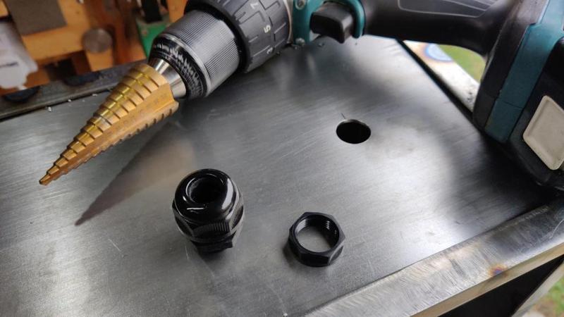
On the right-hand side of the cabinet, I used a step drill to drill a 20 mm hole for the grommet for the incoming power cable and another earthing screw attachment point (not visible in this photo):

2024-01-04-03-drilling-power-in-hole_800.jpg


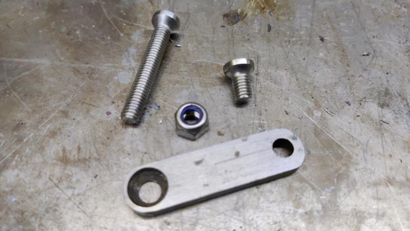
The last job I could think of for the cabinet was to make the door latch. This was made out of whatever bits I could find that looked about the right size. The rotating bit was made from some 12 mm × 5 mm steel, with a 6 mm hole drilled in each end and then both holes countersunk (from opposite sides) with a 10 mm diameter countersink. The countersink was used to drill a deep hole in the steel, so it's effectively counterbored and countersunk. The M6 countersunk screws used with it had their heads turned down to 10 mm (as I didn't want them to poke out the sides of the 12 mm steel). I also turned a simple knob out of 10 mm round bar (not shown in this photo);

2024-01-04-04-latch-pieces_800.jpg


The door part of the latch was just a couple of bits of appropriately sized steel I found. One was drilled and countersunk; the other (the spacer) already had an M10 hole in the middle, which is plenty big enough for the M6 screw to go through.

The moving part of the latch got screwed into the cabinet with a nyloc nut behind the weld nut so I could tighten it and then lock it in place at the point where the latch moved freely. The fixed part of the latch just got tightened directly to the door. This is what it looks like sealed...

2024-01-04-05-latch-sealed_800.jpg


... and open:

2024-01-04-06-latch-open_800.jpg


Fairly simple, but should do the job.

There has been some discussion going on on the MIG-welding forum about the painting process. I quite like the idea of using some sort of filler to fillet the joints between sheet metal and angle iron. On the outside it would clean up the look slightly. On the inside it would hide some of my more awful welds! The obvious option is car body filler but I'm a bit concerned that it might end up needing a lot and it could get quite expensive. An alternative would be exterior decorator's caulk, but I'm not sure how well it would stick to the steel. Any comments welcome...
 
On the chamber itself, I'd reached a point of Analysis Paralysis with lots of possible options (stemming from various discussions on the MIG-welding forum early in the project thread) and a complete inability to make any decisions (hence spending a lot of time focusing on the control cabinet instead).

Today, despite having a terrible night's sleep last night, I decided I just needed to make a decision on how to construct it and just get on with it. Whether the decision is right remains to be seen, but it's what I'm doing anyway.

I've decided to build the frame in a similar way to the cabinet (with sheet metal in the gaps) and with a ceramic fibre blanket lining. If I had mortared the bricks together, I think I would have felt okay with the idea of just wrapping them in a simple steel frame (just on the edges) but I didn't like the idea of the central bricks being unsupported. That meant I either needed to put cross-braces on (which I may still do) or I needed to have the gaps in the frames filled in. In the latter case I figured a ceramic fibre blanket may help a little.

Ideally, I'd use bigger angle iron for the frame (to account for the thickness of the blanket), but I've got lots of nicely cleaned narrow stuff, so I'm going to use that and we'll see what happens.

Anyway, with the decision made, I could start preparing the frame:

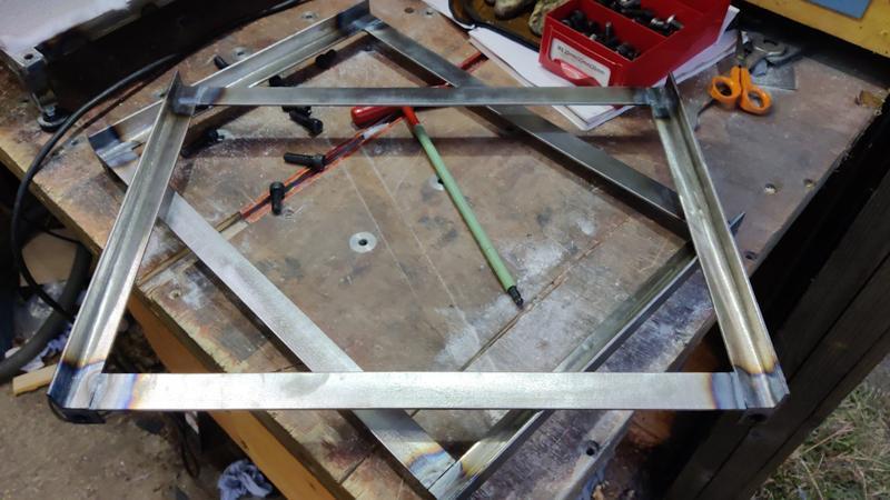
2025-01-05-01-tacking-frame-1_800.jpg


If you look closely at that photo (it's clearer in later ones I think), you'll see there's a bit of a gap where the angle iron pieces meet. That's a result of changing my mind (repeatedly!) about the construction and cutting some of the pieces a bit short (not allowing for the ceramic fibre blanket). The structure will still be plenty strong enough I think and I can always fill in those gaps later if I can be bothered.

I mentioned earlier that I might add a cross-brace. This is roughly what it would look like:

2025-01-05-02-tacked-frame-with-possible-cross-piece_800.jpg


I'll definitely add one of those (out of some wider steel) on the back of the chamber as it'll give me something convenient to attach the thermocouple housings to, but I'm not convinced the top and bottom need it yet. The sides may benefit from something else for reasons I'll get to in due course.

Anyway, I chucked a load of bits of flat bar into the citric acid bath; hopefully if I leave them until next weekend then the mill scale will come off with less effort than was required with the angle iron.

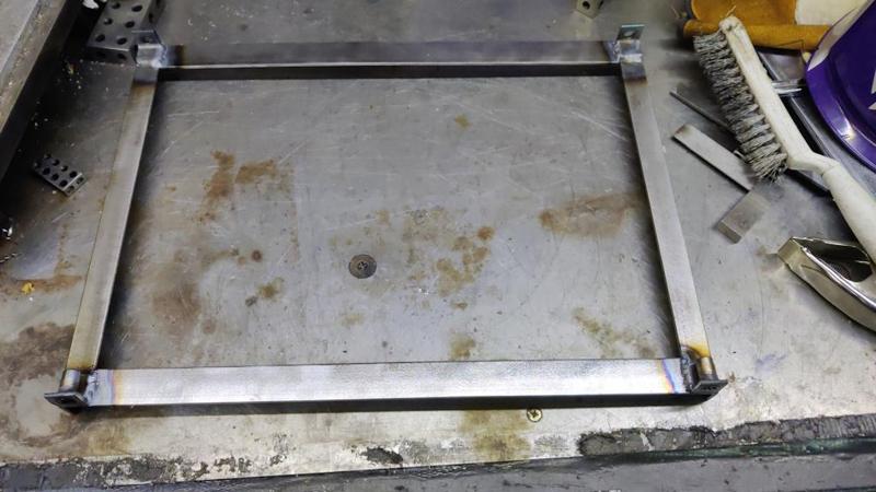
With the frames tacked together and checked for square, I could weld the pieces a bit more rigidly together, just welding along two seams. In this photo you can see that gap I mentioned before:

2025-01-05-03-welded-frame-close-up_800.jpg


It didn't take long at all to get the two frames were welded together:

2025-01-05-04-two-frames-done_800.jpg


To fill in the holes, I used 0.8 mm steel, of which I have plenty (all rust free as well!) Incidentally, sheet metal is one of the reasons why I ditched working in imperial years ago (tapping drill sizes and American numbered/lettered drill sizes being some of the others). Working in metric, I measure a sheet of steel as 0.8 mm and, if I want to order more, I find a (metric) supplier and order 0.8 mm sheet. Working in imperial, I measure the sheet as 0.031" (or if I've got a fancy fractional-reading caliper, 1/32"). So I order 1/32" steel, right? No, you have to go and look up what size that is in SWG or AWG as that's what imperial sheet sizes are typically sold as. When I worked in imperial I found I was constantly having to look stuff up; when I switched to metric that all stopped and I rarely have to consult any data books any more. I've yet to find a down-side to working purely in metric so I can't imagine I'll ever go back.

I plasma cut the sheet steel to size, but this time (unlike the control cabinet) I allowed only a 5 mm overlap with the angle iron. That made it much easier to do the tack welds as I could comfortably start the weld on the 12 mm-ish area of the angle that wasn't covered and then carefully draw the bead back onto the thinner sheet. The first few tacks done:

2025-01-05-05-starting-to-weld-insert_800.jpg


All welded.

2025-01-05-06-welded-insert_800.jpg


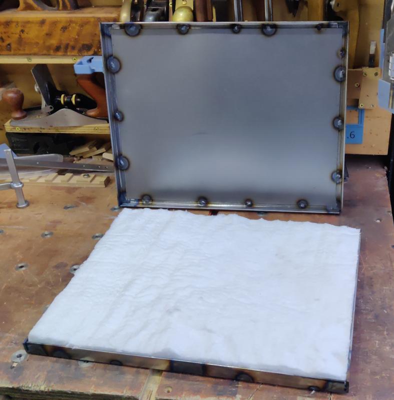
I cut a bit of ceramic fibre blanket to size and shoved it into one of the frames:

2025-01-05-07-ceramic-fibre-blanket_800.jpg


That shows why I said earlier that it probably would have been better to use wider angle iron. Once the bricks are in place pressing down on the blanket, it'll shrink a little and there will be a small overlap of angle iron to bricks, but it'll only be a couple of millimetres I think. Hence the sheet metal is the thing that'll be holding the bricks in place.

I could probably split the ceramic blanket in two (to make it thinner), but I'm going to proceed as-is for now and see what it looks like as the rest of the frame comes together. Back to work tomorrow unfortunately, so there probably won't be a lot of progress until next weekend now.
 
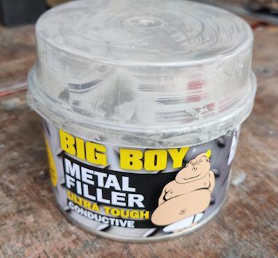
When we last left the control cabinet, I was discussing the idea of filleting the corners with some filler (mainly to cover up some slightly shoddy welding in a couple of places). I bought some of this horrible stuff:

2025-01-17-01-nasty-filler_800.jpg


I say horrible as it's awful to work with. It cures in about five minutes, which is nowhere near long enough for this sort of job. The blurb says its ready for sanding in just 15 minutes, but it would need a heck of a lot less sanding if it cured more slowly and hence allowed you to get it in the right place.

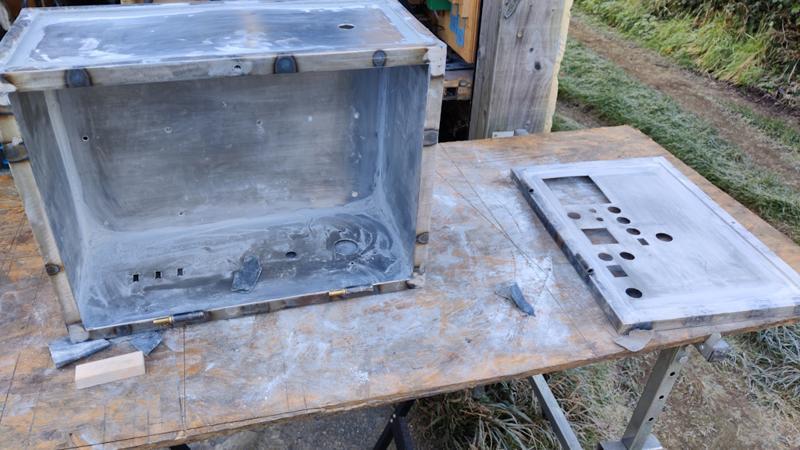
Anyway, I applied it (a sixth of a tub at a time, mixed with 2.5 g of the hardener). It was very hard to get it to go where you wanted without it also going everywhere else, so I then had a fairly long period of sanding and making vast amounts of filler dust.

2025-01-17-02-filled-and-lots-of-sanding-happening_800.jpg


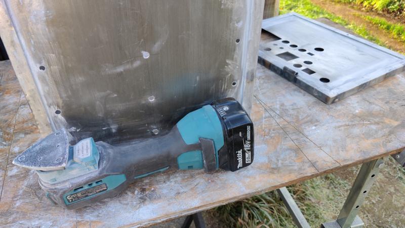
Where I could, I used a sanding plate mounted on an oscillating multi-tool (with a respirator on):

2025-01-17-03-aggressive-sanding_800.jpg


This is the first time I've used a sanding pad on the cordless multi-tool and it's a lot more frustrating to use than on the mains-powered (Fein) one. The Makita one uses a pin to hold the bit/pad in place, but that means you have to peel off the sandpaper to be able to get at the pin if you want to change the orientation of the pad. With the Fein tool, you just pull the lever to release the pad, turn the pad to the new orientation and push it back on again.

Anyway, after a lot of oscillating multi-tool powered sanding, there was then a lot of hand sanding (again while wearing a respirator)...

2025-01-17-04-hand-sanding_800.jpg


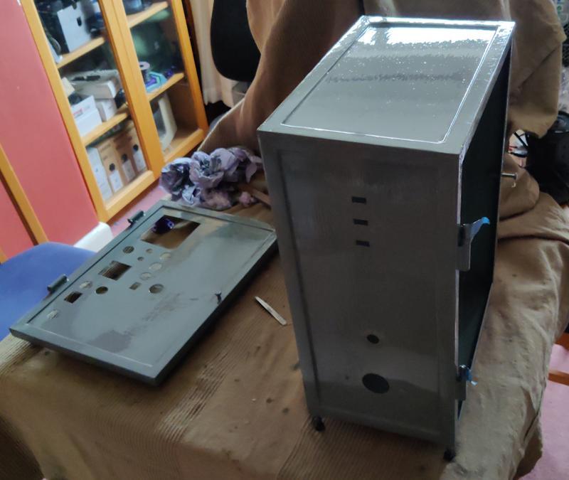
... and then a lot of vacuuming and compressed-air blowing of dust. I then colonised the end of the dining room table (with thick cotton throw thing covering up the table surface and the back of my laptop and monitors) and applied the paint. I used Jenolite Directorust Slate Grey Satin paint; I bought a litre of it and used substantially less than a quarter of the tin.

2025-01-17-05-dining-room-table_800.jpg


I used what I think is a relatively posh brush (Hamilton Perfection Pure Bristle), but, like every other paint brush I've ever used, I spent half the time picking loose bristles out of the paint using a pair of tweezers. After applying two coats with the Hamilton brush, I used a cheap foam paint brush for the bits that needed touching up.

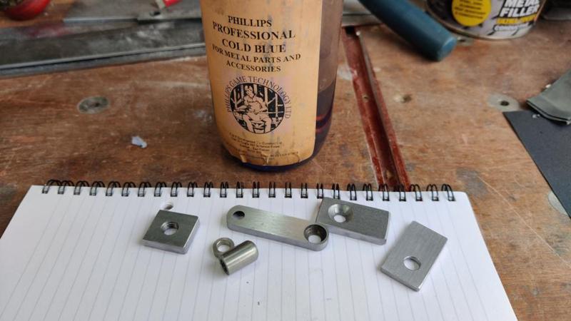
While the paint was drying, I made a couple of extra bits for the latch. I didn't want the moving part of the latch to be rubbing against the paint, so I made a small metal spacer for the fixed parts and a washer for the moving parts. All the latch parts then got a bath in some cold blue to give them a bit of protection:

2025-01-17-06-bluing-latch-parts_800.jpg


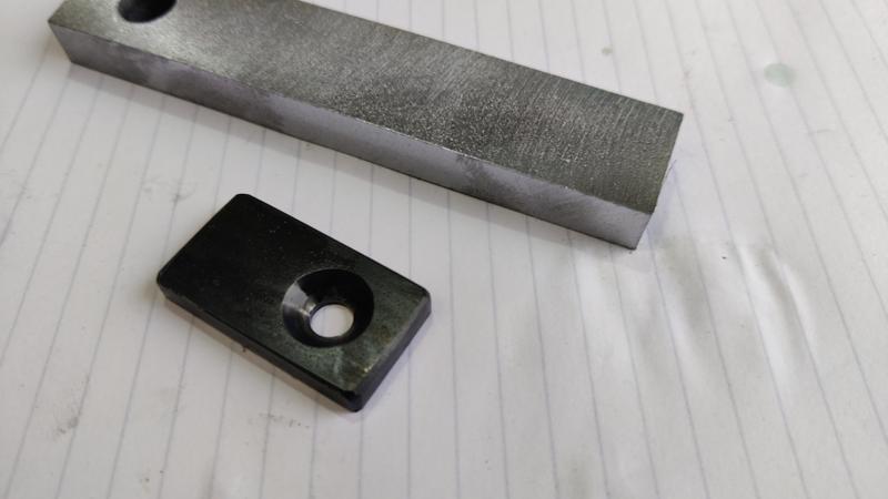
This picture shows one of the blued parts next to a bit of mild steel to show the difference to the colour:

2025-01-17-07-blued-next-to-not_800.jpg


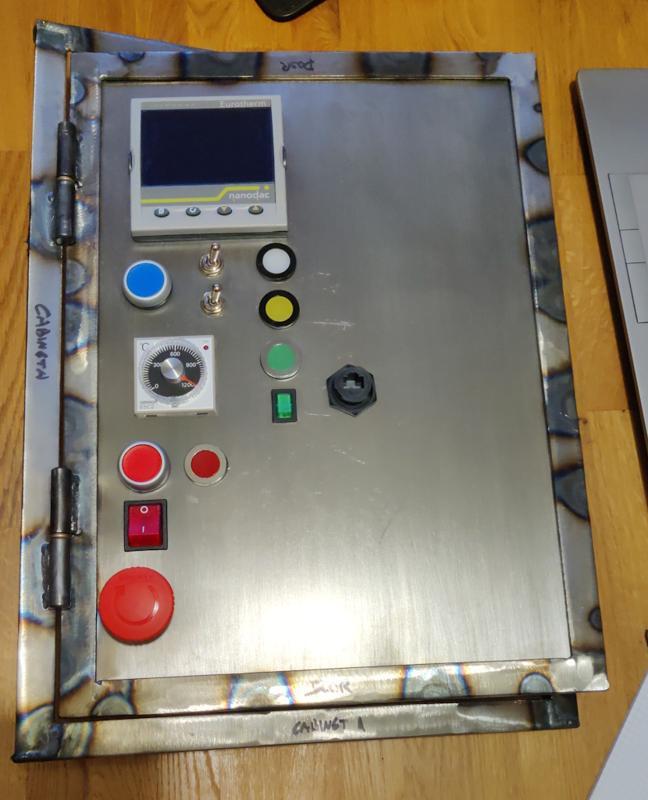
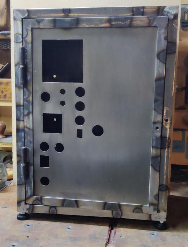
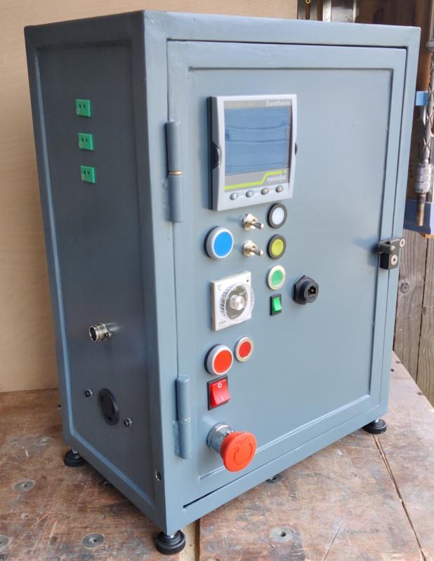
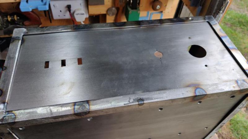
With that done and the paint dry, I could fit the various bits of electrickery into the cabinet and get some photos. The outside of the box:

2025-01-17-08-cabinet-outside_800.jpg


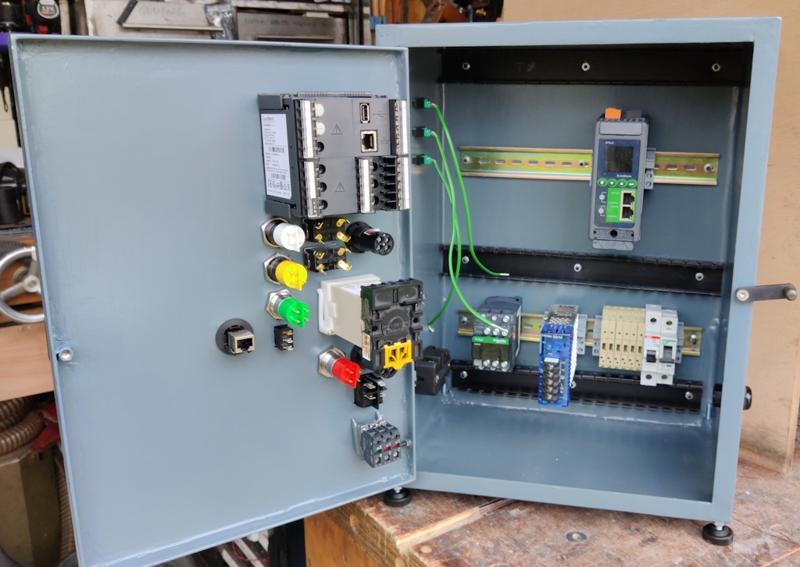
The inside:

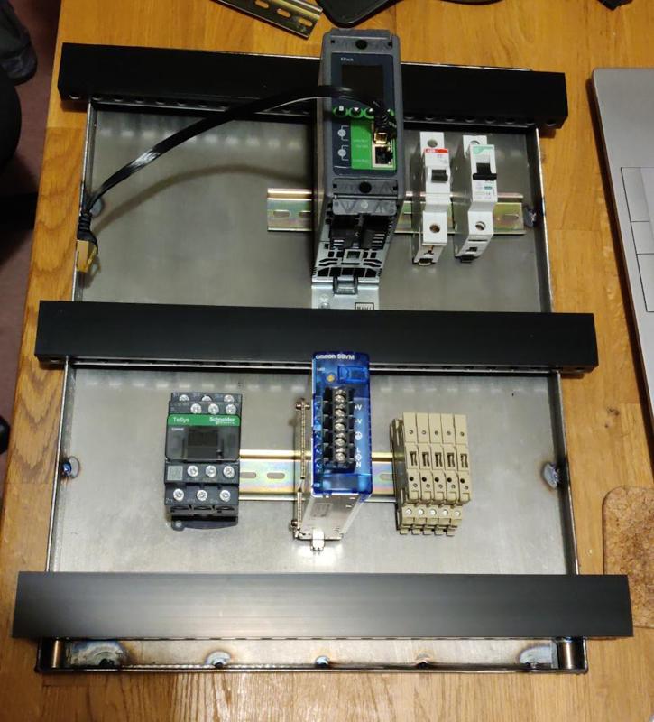
2025-01-17-09-cabinet-open_800.jpg


As you can see, I haven't really started the wiring yet: the only thing I've done so far is attach the thermocouple cable to the three thermocouple sockets as I figured that would be easier before fitting them into the cabinet. Wiring it up will be something I can do gradually while sitting in the warmth of the house!
Overall, I'm really pleased with how the cabinet is looking. I still detest painting (although not as much as I now detest car body filler!), but that's easily the best-looking paint job I've ever done; I'd definitely use the Jenolite paint again. It would have saved several weeks and a lot of work to just buy a simple project box and cut holes in it as required, but there's something quite satisfying about having made it from scratch myself.
 
That looks so much like a professional enclosure... presumably you can buy them ready made in a range of sizes... but where's the fun or skill development in that?!
 
Dr. Al, does your 'cold blue' treatment wear well?
Many years ago I used to use gun metal blue on our rifle barrels and needed to reapply every few years. I'm assuming it is the same as yours.
 
Dr. Al, does your 'cold blue' treatment wear well?
Many years ago I used to use gun metal blue on our rifle barrels and needed to reapply every few years. I'm assuming it is the same as yours.

Honestly, I'm not sure: I rarely use it. Most of the tools I make stay in the workshop (which has a dehumidifier) and rarely see any rust. As a result, I don't tend to bother treating most metal parts and just leave them bare. The only reason I'm painting / bluing stuff for this is that it'll live in a separate "lock-up" (rented garage elsewhere) that has a higher likelihood of damp.


Yours looks like it's a bit further on with the wiring than mine!
 
Al, I came across this a few days ago.


I haven't watched it yet but thought of you!
Thanks Nick. Someone shared that on the MIG-welding forum earlier on in the build. It's not one of the better videos I've seen on the subject to be honest: lots of whinging about how it didn't work because he rushed/bodged various parts of the job.
 
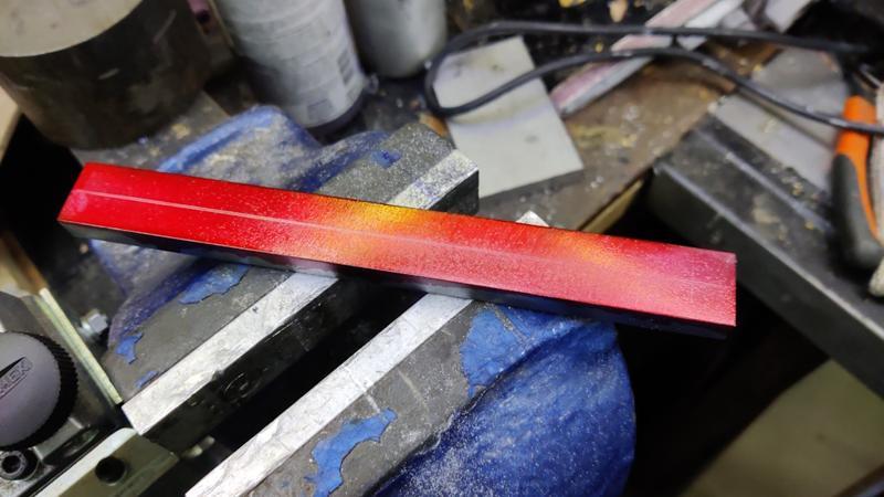
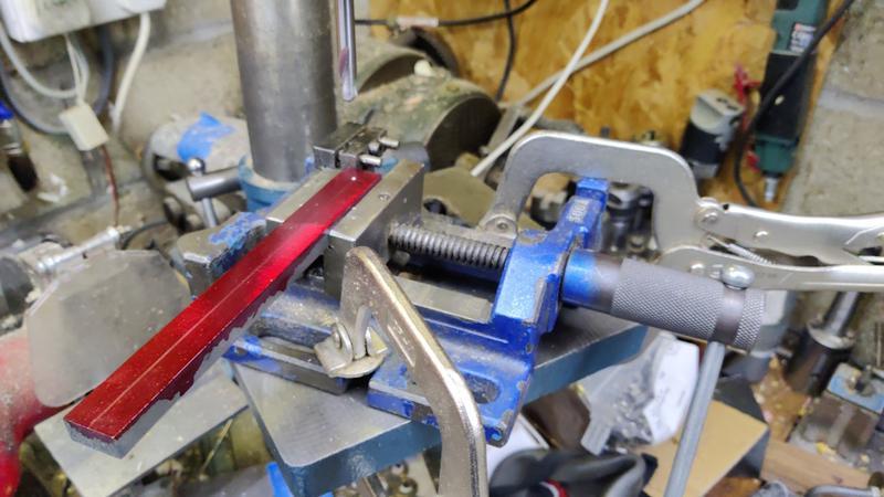
Back to the chamber. I found a bit of 20 mm × 10 mm steel bar in the drawer and marked it up with Dykem red. I then scribed a centre line down the middle:

2025-01-18-01-bracket-bar_800.jpg


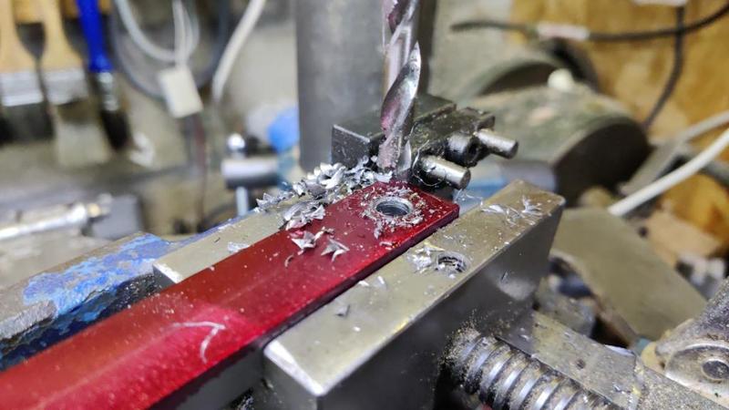
It then went through a repeated sequence of spot drill...

2025-01-18-02-spot-drill-bracket_800.jpg


... drill (6.8 mm) ...

2025-01-18-03-drilled-bracket_800.jpg


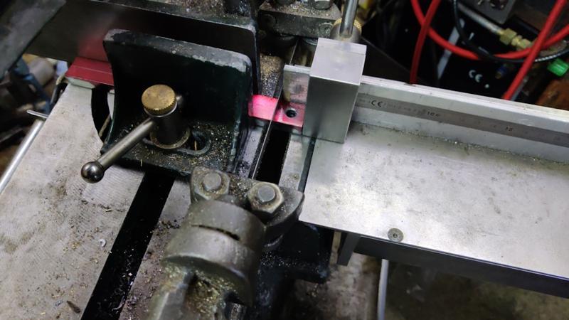
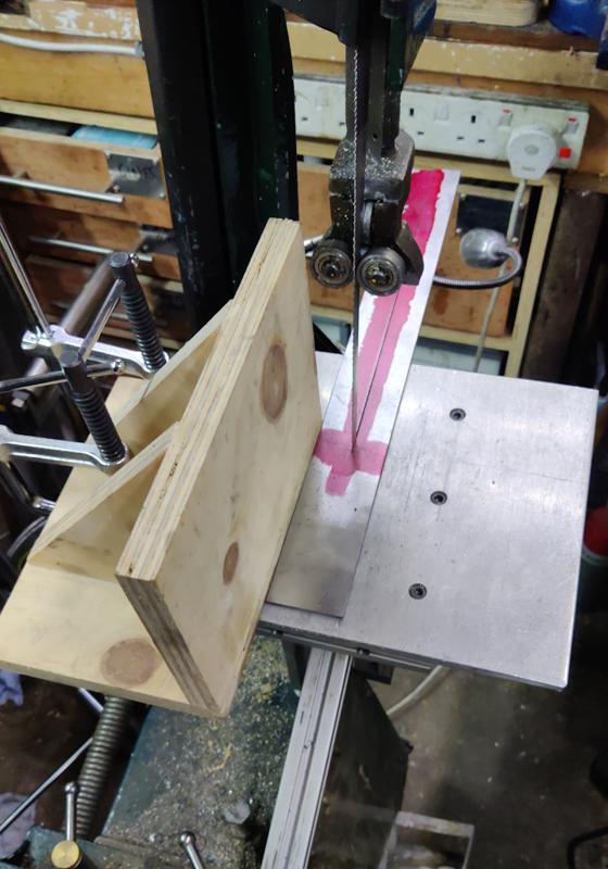
... and bandsaw, using my Bandsaw Cut-Off Table for a consistent length of each piece:

2025-01-18-04-cut-off-table_800.jpg


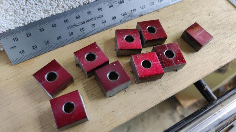
That gave me this pile of little brackets:

2025-01-18-05-not-enough-brackets_800.jpg


In my head that had been enough pieces for all the side joints (I'm going to make the chamber dismantle-able rather than welding it together permanently). I was obvious not running on all cylinders that day as there needed to be 16 of them, not 8, so an alternative plan was needed for the extra bits (I'd used up all of that size of steel bar).

Anyway, I decided to worry about that later and just welded the brackets onto the top and bottom frames of the chamber:

2025-01-18-06-brackets-welded-on_800.jpg


At that point, the holes were still 6.8 mm. The plan was for one frame to have M8 threaded holes and the other to have clearance holes, but I figured it was easier to do that after welding them in place as that way I wouldn't have to worry about which bracket went on which frame.

For the other halves of the joints (which were going to be made from the imaginary 8 other bits of that flat bar), I cut some short lengths of 3 mm × 20 mm angle iron. While I had the bandsaw set up with its cut-off table, I also cut some short lengths of 20 mm square box section and some bits of 20 mm flat bar:

2025-01-18-07-lots-of-bits-of-metal_800.jpg


The box section pieces got tack-welded onto one of the frames, using a handy little spring clamp to hold them in place and some TIG filler wire to lift up one end (as my bandsaw vice has slipped a bit and needs re-adjusting for square cuts!)

2025-01-18-08-magnetic-clamp_800.jpg


That clamp really comes into its own when you're welding something onto an up-right, but it's useful now-and-then for horizontal stuff too.

I then welded some weld nuts ("cylindrical coupling nuts") into four of the angle iron pieces and also into the flat bar pieces. The angle iron pieces with plain holes got welded onto the end of some longer bits of angle iron:

2025-01-18-09-welded-in-nuts-and-plain-brackets_800.jpg


The bits of flat bar with their weld nuts then got tack-welded onto the ends of the upright box section pieces:

2025-01-18-10-welding-foot-screws_800.jpg


With all those pieces tack-welded in place, I could then work around all four sides of either end of each of the box section pieces to firmly attach them to the base frame:

2025-01-18-11-finishing-base-welding_800.jpg


The box section piece provide somewhere for the chamber feet to go:

2025-01-18-12-foot_800.jpg


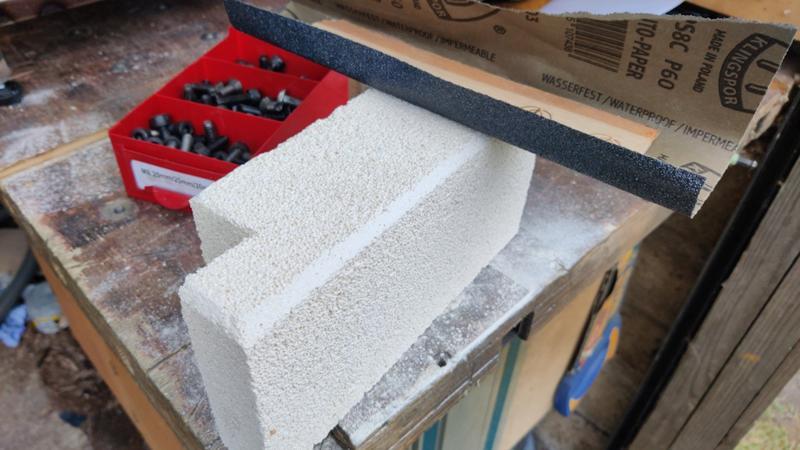
It was then time to start a rough assembly of the chamber pieces so that I could work out whether I'd got the lengths of the angle iron uprights correct. Before doing that, I applied a chamfer to the front-most bricks with some sandpaper wrapped around a bit of wood:

2025-01-18-13-chamfering-edges_800.jpg


That chamber is there to allow the front of the bricks to be flush with the outside of the front bits of angle iron so that the door can close and produce a good brick-to-brick seal.

With the chamfers applied (and the holes in the lower frame tapped M8), I could start assembling the frame:

2025-01-18-14-assembling-frame_800.jpg


It turned out that I'd judged the length of the angle iron uprights just fine, so I welded on the other bits of angle iron (the ones with the weld nuts fitted) and then (after drilling out the holes in the top frame brackets), I could assemble the frame:

2025-01-18-15-assembled-frame_800.jpg


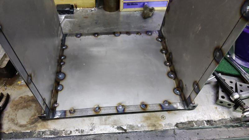
I want to put some sheet across the sides (and probably the back) as well as the top and bottom. To make that sheet easier to fit, I decided to turn the individual uprights into frames. I had some flat bar that I'd de-mill-scaled in citric acid, so I cut the flat bar to length and then welded it between the angle iron pieces to make frames:

2025-01-18-16-welding-flat-bar_800.jpg


This shows the other side of the two frames:

2025-01-18-17-side-frames-welded_800.jpg


They could then be test-fitted:

2025-01-18-18-side-frames-fitted_800.jpg


Tomorrow I'll cut-to-size and weld in some bits of 0.8 mm sheet to fill in the side gaps and then see if it'll still go together once I've put some more ceramic fibre blanket into the sides. I'll then have to figure out what to do about the back:

2025-01-18-19-rear-view_800.jpg


I still haven't completely decided on the brick layout for the back. I also need to decide what to do in the way of joining the angle iron up (e.g. like the flat bar on the sides), whether to add ceramic fibre blanket and steel sheet and also how to mount the thermocouples and heater connections. Hopefully I'll get all that sorted tomorrow and then I've just got the rather daunting job of figuring out the door (especially daunting as I don't think I've got enough 20 mm angle iron to make the door in the same was as the chamber and also I'll have the challenge of getting it hinged in a suitably robust way).
 
A big landmark was achieved today, although I'm not sure I'd say it went well exactly. Nevertheless, we are where we are...

I started by cutting and tack-welding in the side sheets. I didn't take any photos of that process as it's much the same as how I did the sheets on the top and bottom. I decided I wanted to have a frame around the back to give me something to attach the back sheet to, but I didn't have any more of the 25 mm wide flat bar (or at least, I didn't have any with the mill scale removed). I had some spare 50 mm bar though, so I used the home-made vertical saw table for the bandsaw to cut the 50 mm bar in half:

2025-01-19-01-sawing-bar-in-half_800.jpg


The two halves then got welded in place with the frame assembled as that seemed the easiest way to make sure everything stayed in the right place:

2025-01-19-02-welding-in-situ_800.jpg


I'd decided (before thinking about having bars top and bottom) to have a diagonal bar to mount thermocouples on. With hindsight this could have been done in a much more sensible way with a horizontal bar across the middle (it didn't need to be diagonal with the strength from the top and bottom bar and a middle bar wouldn't have got in the way later...)

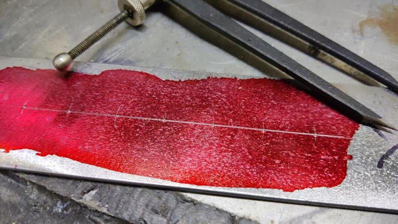
Anyway, with the bar cut to fit the gap, I used some dividers to mark out some points on an 18.5 mm pitch. The central point got ignored, the outer six got centre punched:

2025-01-19-03-dividing-diagonal-bar_800.jpg


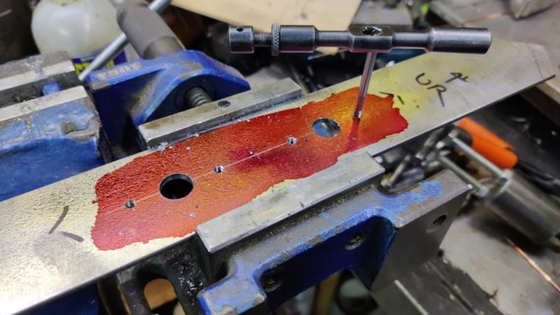
All the holes were spot drilled and drilled 3.2 mm, then two were enlarged in two stages to 13 mm and the rest were tapped M4:

2025-01-19-04-tapping-diagonal-bar_800.jpg


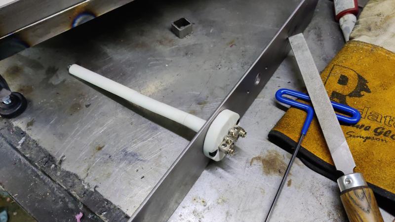
That allowed me to do a test fit of one of the thermocouples:

2025-01-19-05-test-fit-thermocouple_800.jpg


I'm assuming that I can shorten those thermocouples by undoing the screws, removing some of the ceramic insulators, chopping the wire and then reassembling. I'd welcome any comments from anyone who's done that before I bite the bullet!

The diagonal piece got welded in situ as well:

2025-01-19-06-welded-diagonal_800.jpg


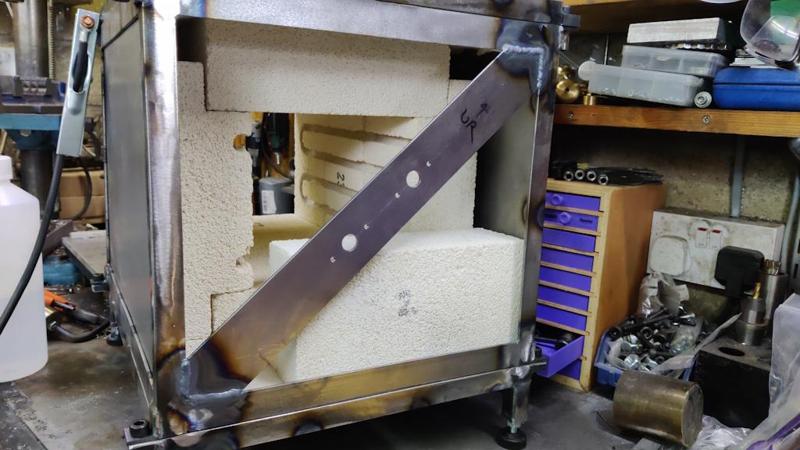
I plasma cut another bit of 0.8 mm steel sheet and tack welded that in place.

2025-01-19-07-back-sheet-welded_800.jpg


That's the last bit of sheet welding I'll need to do on the chamber itself (there's still the door to come later when I figure that out) and I'm really happy with the way the welds went. I won't bother with any filler on the chamber (which is almost certainly a good thing as I don't know how it will cope with the temperature!)

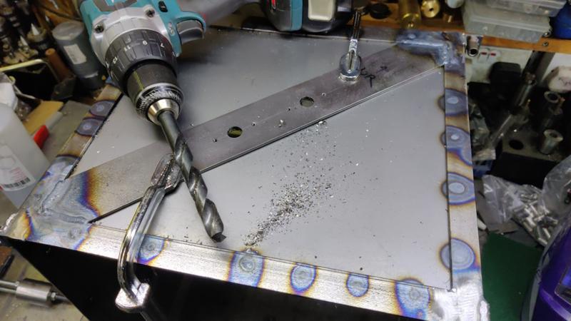
The sheet had obviously covered up the thermocouple holes, so I just used the cordless drill to sort that out, with some clamps to hold the sheet to the diagonal as the sheet is only welded around the edge:

2025-01-19-08-drilling-through-thermocouple-holes_800.jpg


It was then time to start thinking about assembling stuff, but first I had to saw the back bricks to size...

2025-01-19-09-sawing-bricks_800.jpg


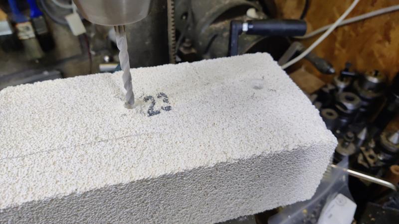
... and then drill some holes for the heating element to come through (I also drilled some shallow larger holes in the other side to house a shroud that you'll see later):

2025-01-19-10-drilling-bricks_800.jpg


The next part was (predictably enough) a bit of a chore that didn't go especially well. I needed to feed the element through the slot in the bricks. For the first side, I clamped the three bricks together and used a pair of needle-nose pliers to feed it gradually through:

2025-01-19-11-feeding-coil-through-first-side_800.jpg


That worked, but (unsurprisingly) there was a lot of break-out on the flimsy bits of brick that are supposed to hold the element in place. With hindsight I suspect it would have been better to just have it as an open slot (rather than trying to keep the element in place with brick shaping) and find an alternative method of fixing it. I may still need to find an alternative method of fixing it, but we'll see what happens when I first bring it up to temperature.

2025-01-19-12-fed-coil-through-first-side_800.jpg


After umming and ah-ing about various options for crimping / otherwise-joining a copper or similar sleeve onto the ends of the wire and concluding that (a) it would be an awkward job and (b) the copper might well just melt once the chamber got up to temperature, I decided to just double the ends of the wires up for the route through the bricks. I heated the ends up (and while I was at it, the rest of the coil) to anneal them, then straightened the ends, annealed them again, doubled them over, annealed them again, cleaned all the oxidation off with some scotchbrite, then twisted them together and squeezed them tight (with a pair of high force pliers) wherever there was contact. Hopefully the fact that they're tight together on the contact points will help keep those areas free of oxidisation and they'll maintain a good electrical contact.

2025-01-19-13-twisted-ends_800.jpg


I could then fit the first set of coils and the rear bricks, using some TIG shrouds to insulate the wire from the metalwork.

2025-01-19-14-in-situ-with-tig-shrouds_800.jpg


For the second element, I decided to start in the middle rather than at one end. I fed the coil into the central section until it stuck out the same amount at both ends:

2025-01-19-15-starting-in-the-middle_800.jpg


Then fed it into the other bricks, this time keeping the bricks separate so that I could grab the element with two hands (one feeding in, one pulling out):

2025-01-19-16-part-way-through_800.jpg


That went together much, much quicker than the first one and there was much less break-out (although there are still a few places where the coil is unsupported, so I'm still considering an alternative fixing method.

2025-01-19-17-second-coil_800.jpg


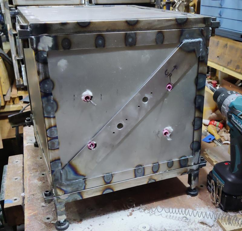
It was then time to make some holes in the side/back frame for the element wires to come out. This is where it would have been much, much better to have a horizontal bar for the thermocouples to mount in as the element wires would just have had to come through sheet metal. As it is, one had to come through sheet metal and the diagonal and one had to come through sheet metal and partially the diagonal. That made for some interesting drilling! I used a step drill in the pillar drill for the two holes that were on the diagonal. I was very lucky that the diagonal was the way round it was as I could just get the pillar drill lined up on those holes, with the handles in the gap to the right. If it had been on the other diagonal I wouldn't have been able to use the pillar drill.

2025-01-19-18-iffy-drilling_800.jpg


The other two holes (just in sheet metal) were drilled with the same step drill, but using a cordless drill.

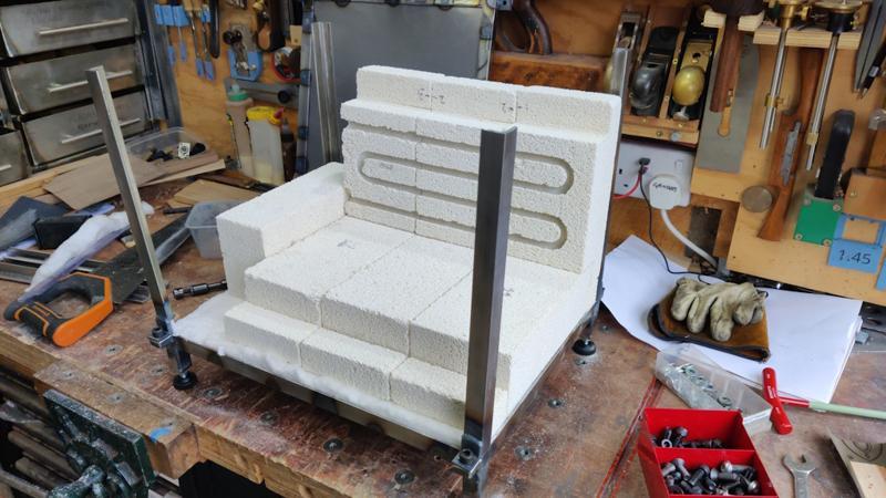
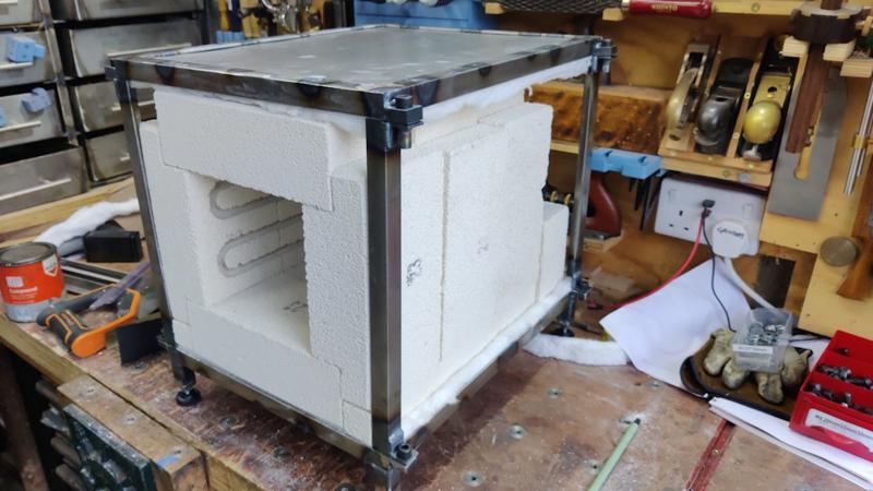
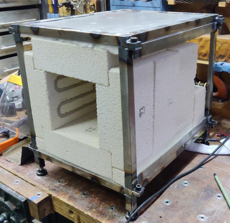
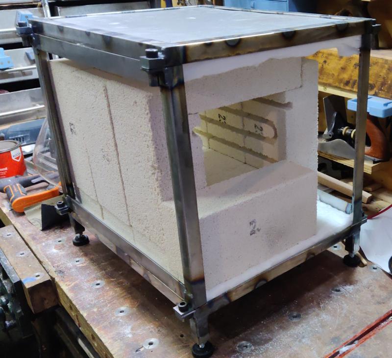
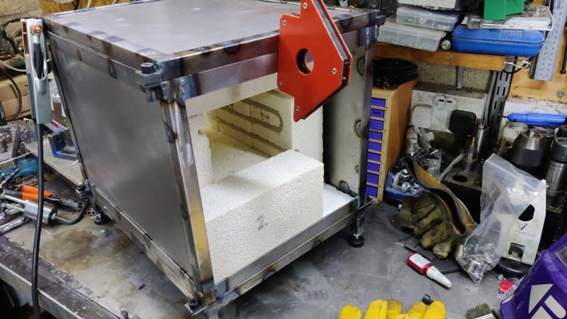
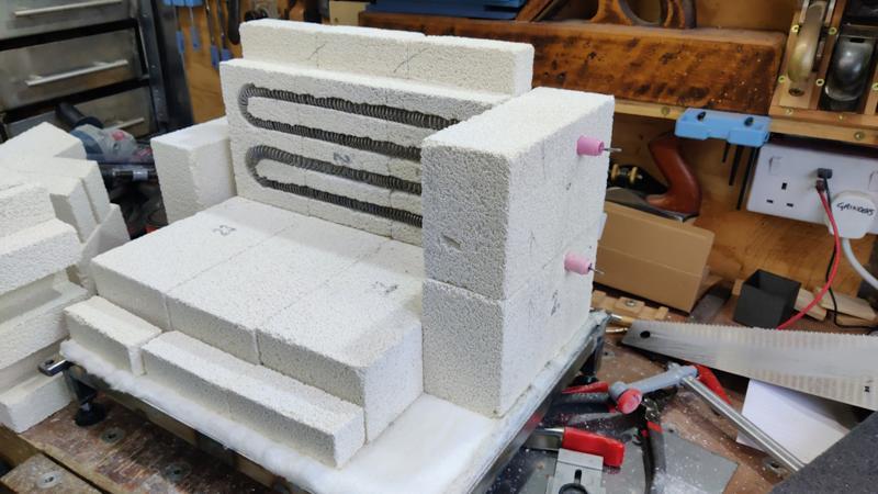
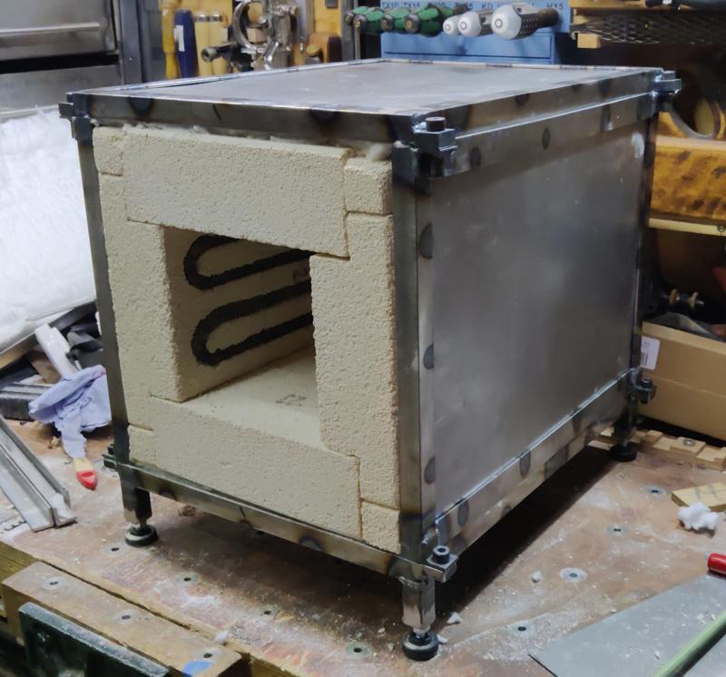
There was then a long period in which I didn't take any photos, but in which much manoeuvring, much adjusting with clamps and a little bit of swearing happened. At the end of that period, the bricks were all assembled, wrapped on five sides with ceramic blanket and the main body of the chamber is mostly complete:

2025-01-19-19-chamber-assembled_800.jpg


In this photo you can see where the element coil ends come out. If you look closely you'll see that the bottom-left hole is **just** within the diagonal bar whereas the top-right one was about half-and-half so it's quite amazing how well the pillar drill and step drill coped with that really.

2025-01-19-20-chamber-rear_800.jpg


Hopefully that won't need taking apart again. I may even decide to paint it as-is rather than dismantling it and painting the parts. Painting the parts would be better I'm sure, but it was quite tough to get together!

It still needs a hinge and latch fitting (for the door), along with a decent earth stud, the interlock switch for the door and I need to finish off those connections on the back, but it's definitely a big landmark.

I'm not sure exactly what I'd do differently if I decided to do it again, but I'd definitely do it differently! Assembling the frame was not a straightforward process.

I might start having a go at wiring up the control cabinet during the week. Hopefully next weekend I'll figure out what I'm doing with the door.
 
Back
Top