• Hi all and welcome to TheWoodHaven2 brought into the 21st Century, kicking and screaming! We all have Alasdair to thank for the vast bulk of the heavy lifting to get us here, no more so than me because he's taken away a huge burden of responsibility from my shoulders and brought us to this new shiny home, with all your previous content (hopefully) still intact! Please peruse and feed back. There is still plenty to do, like changing the colour scheme, adding the banner graphic, tweaking the odd setting here and there so I have added a new thread in the 'Technical Issues, Bugs and Feature Requests' forum for you to add any issues you find, any missing settings or just anything you'd like to see added/removed from the feature set that Xenforo offers. We will get to everything over the coming weeks so please be patient, but add anything at all to the thread I mention above and we promise to get to them over the next few days/weeks/months. In the meantime, please enjoy!

Heat Treatment Oven

I've been fairly busy with things unrelated to this project for the last couple of weeks, but I have managed to spend some time in the evenings wiring up the control cabinet and I now feel that it's reasonably complete. This is what it looks like inside (with the two ethernet cables - the one from the Nanodac controller to the EPack thyristor module and the one from the EPack to the door - removed so the wiring behind can be seen more clearly):
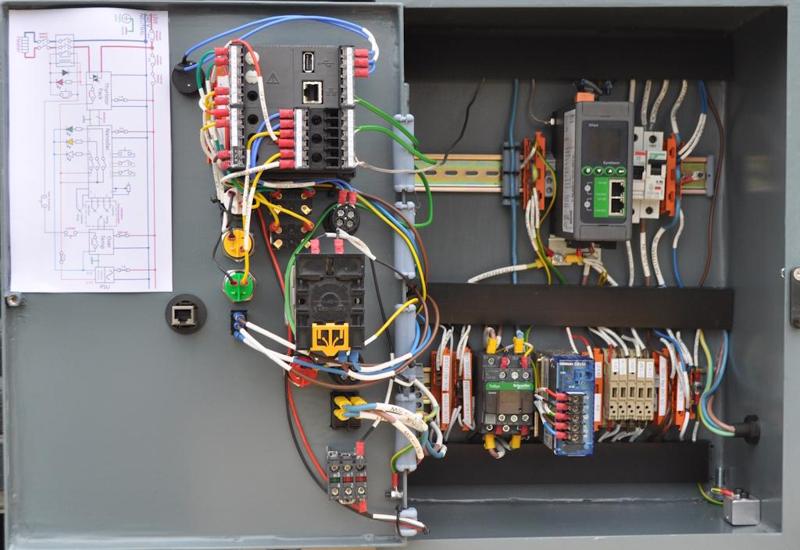
2025-02-01-01-cabinet-wiring-complete-no-ethernet_800.jpg


It took a lot of thought to get everything laid out moderately neatly, but I'm pleased with the result. The photo makes it look like the cable trunking isn't parallel, but that's just a camera perspective effect.

I went a bit over the top on labelling and such-like. It's unlikely I'll revisit this wiring for a very long time, so I figured it would be helpful to have everything labelled clearly for whenever I do need to revisit it. Almost every wire has a heat shrink printed label on both ends showing where it's going from and to (the only exceptions are those that are so short or obvious that it's easy to trace the wire and even those have a label on one of the ends). The Wago connector blocks are also labelled with their purpose (with the exception of the ones at the top, which are quite obviously neutral and earth points).

After wiring it up, I went round with a multimeter and checked that any bit of metalwork (including the DIN rails) had a decent earth connection. The door has a dedicated earth wire, even though it's probably earthed perfectly well via the hinges. It's not obvious in the photo, but I added a couple of short bits of cable trunking on the left-hand side of the cabinet to route the wires from the trunking up to the door. Those bits of trunking have the covers cut a bit short (to allow the cables to 'escape') and the covers are cable tied in place (to stop the cables pulling the covers off when the door is closed).

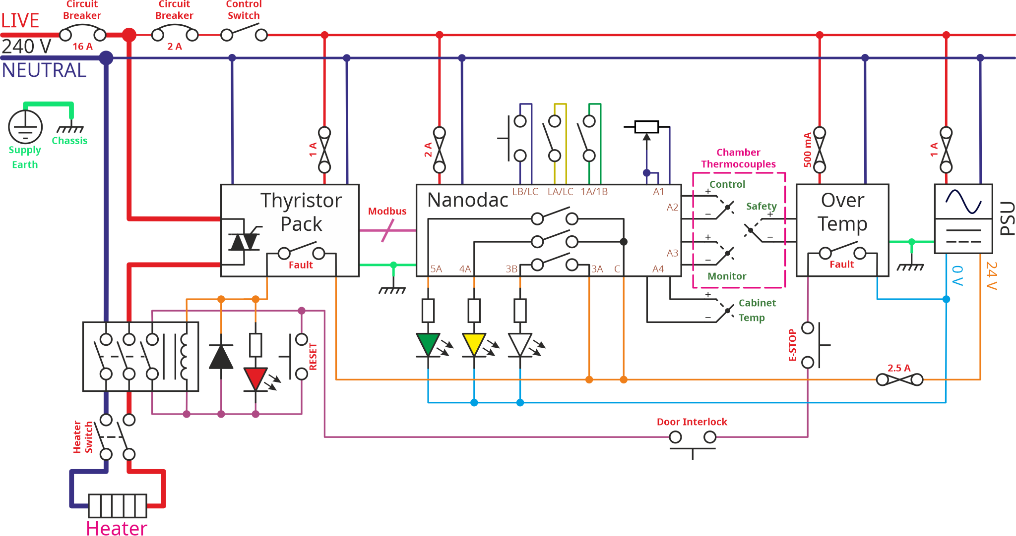
As you can see, I also printed out the wiring diagram and blue-tacked it into the door for future reference. That's an updated version of the wiring diagram, drawn after finishing wiring the cabinet. Inevitably the wiring differed a bit from the original plan: all the various cut-out switches (over temperature, emergency stop etc) have to be wired in series, but the order doesn't matter. When I wired the cabinet up, I wired them in the order that resulted in the neatest layout and it seemed sensible to update the drawing to match the actual wiring. While I was at it, I included the details of all the "user interface" (switches, lamps and a potentiometer) connections to the controller and also the fuse and circuit breaker ratings.

This is the updated schematic:
FinalControlCabinetSchematic.png


It's not as tidy as the previous version, but I think it's still perfectly readable.

This is what the wiring looks like with the covers off the trunking (and with the ethernet cables now fitted):
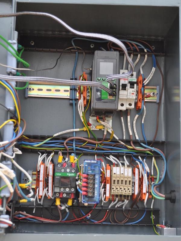
2025-02-01-02-covers-off_800.jpg


Definitely a lot more messy, but not too bad considering how many connections there are.

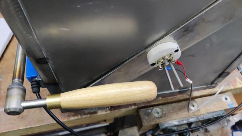
The eagle-eyed among you will notice a connection going into the top-left of the EPack thyristor module. That's a little thermocouple with a threaded fitting. I thought it would be interesting to have a temperature sensor showing how hot the control cabinet got. It's obviously going to be a lot cooler than the chamber and there probably isn't much point, but nevertheless it might be interesting to see if the electronic bits and bobs start getting hot. The EPack is likely to be the hottest thing in the box, so I decided to fit the thermocouple to its heatsink. I had a K-type thermocouple with a threaded end, so I decided to risk voiding the warranty (which I obviously don't have given that it was given to me for free!) by drilling a 5.1 mm hole in the heatsink...
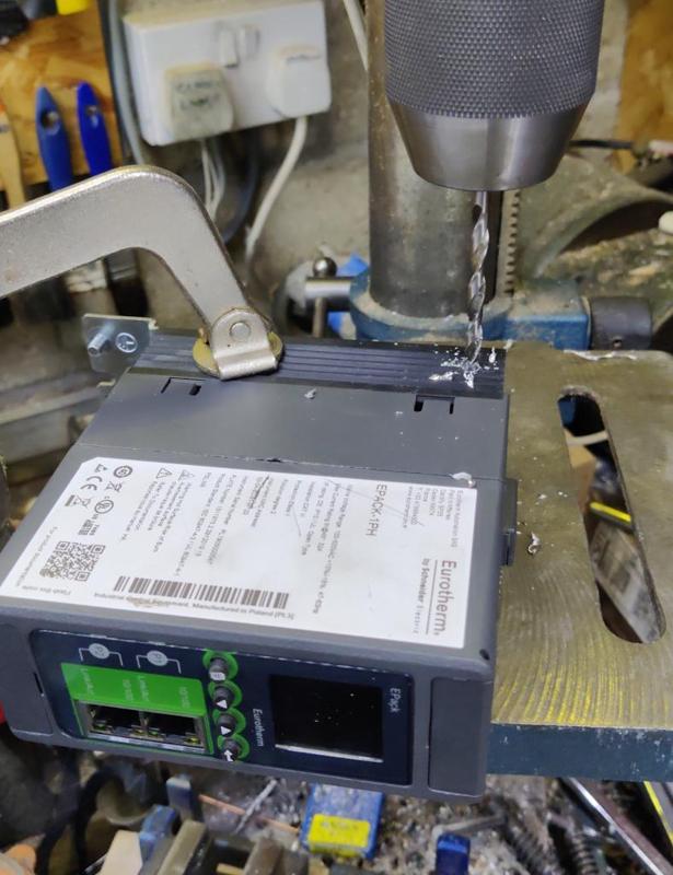
2025-02-01-02a-drilling-epack_800.jpg


... and then tapping it 1/4" UNC to match the antediluvian thread on the thermocouple:
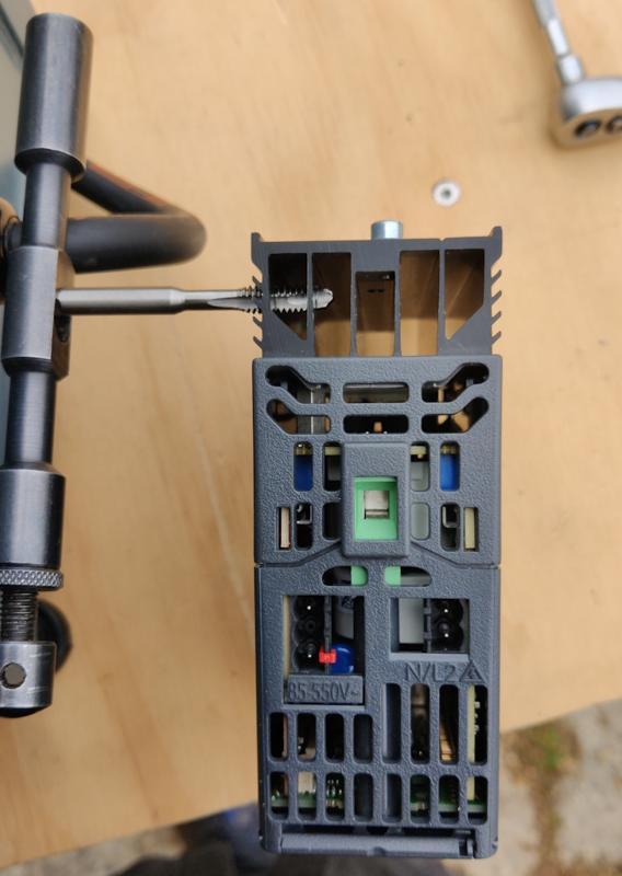
2025-02-01-02b-tapping-epack_800.jpg


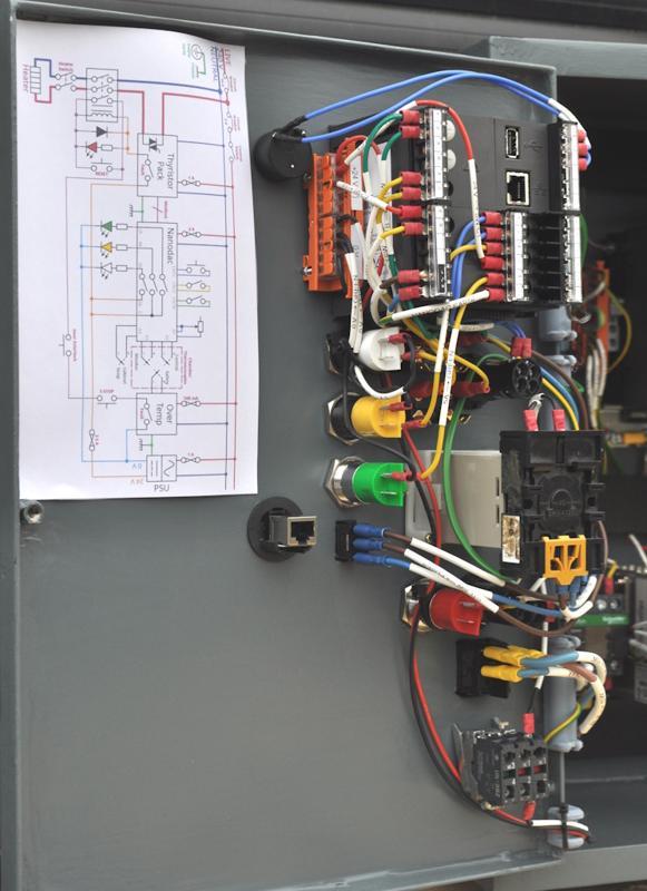
This photo shows a bit of detail of the door wiring. The orange Wago block gives a central distribution point for 24 V and 0 V. It was an amazingly good fit in a little "indent" in the side of the Nanodac controller, so it seemed a good idea to tuck it in there:
2025-02-01-03-door-detail_800.jpg


The wiring is, perhaps, a bit more messy than that at the back of the cabinet, but not too bad all things considered.

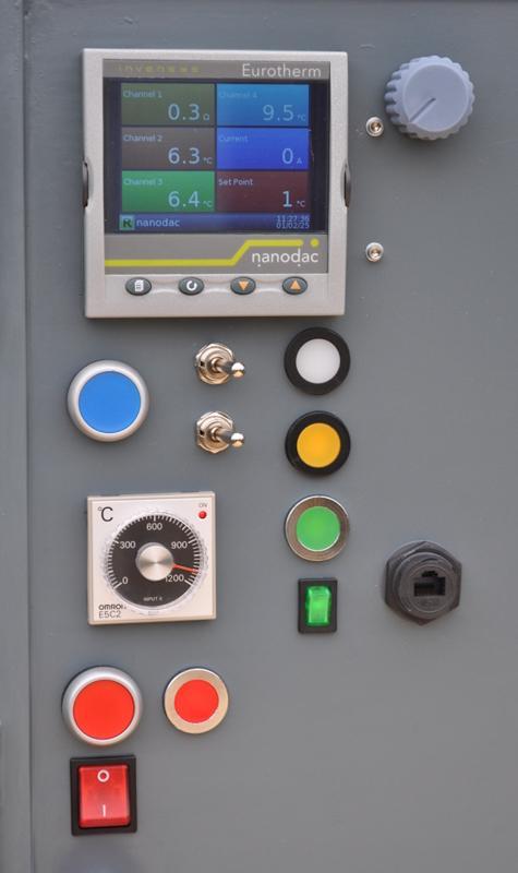
With the wiring all complete, I decided it was time to power it up and have a go:
2025-02-01-04-powered-up_800.jpg


It was amazingly satisfying to hear the "thunk" of the contactor pulling in (and see the red lamp come on) when I pressed the big red button (which bypasses the auxiliary contact on the relay - the auxiliary contact effectively acts as a no-volt release and the red button resets that release).

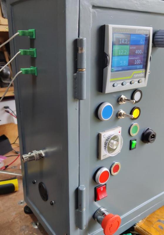
I was also really pleased that the over-temperature trip seems to be working. With a thermocouple plugged into the port on the side of the cabinet, I wound the dial down and, when it got down below the 20°C mark, the light on the over-temperature trip went off, the contactor "thunked" as it disengaged and the red lamp turned off.

The green rocker switch (beneath the three lamps) controls the power to all the electronic bits in the cabinet so that's the first thing that gets turned on when starting. The red push button is, as described before, the reset for the no-volt release; the red lamp next to it shows when the contactor is closed. The big red rocker switch beneath it goes between the contactor and the heater output so acts as a manual means of disconnecting heater power if required. The rest of the controls (blue push button, two toggle switches, white, yellow & green lamps and the dial in the top-right) are all connected to the Nanodac controller.

The program I've got in the Nanodac at the moment is still a bit of a work-in-progress but so far the things I've got working are:

  • The potentiometer (blue dial in the top-right of the photo above) adjusts the set-point (target temperature) with a range of 0°C up to about 1200°C. I won't ever take it right up to that limit as that's getting a bit close to the maximum rating of the chamber components (1260°C).
  • The top one of the two toggle switches selects whether to use the potentiometer-configured set-point (switch to the right) or use a hard-coded set-point (currently 810°C) if the switch is to the left.
  • The green light comes on when the temperature is within 5°C of the set-point.
  • The bottom toggle switch currently just turns the yellow light on and off! I'll come up with something more useful for that in due course.
  • The blue push button does nothing at all at the moment and I haven't had any ideas of what it might be useful for yet!

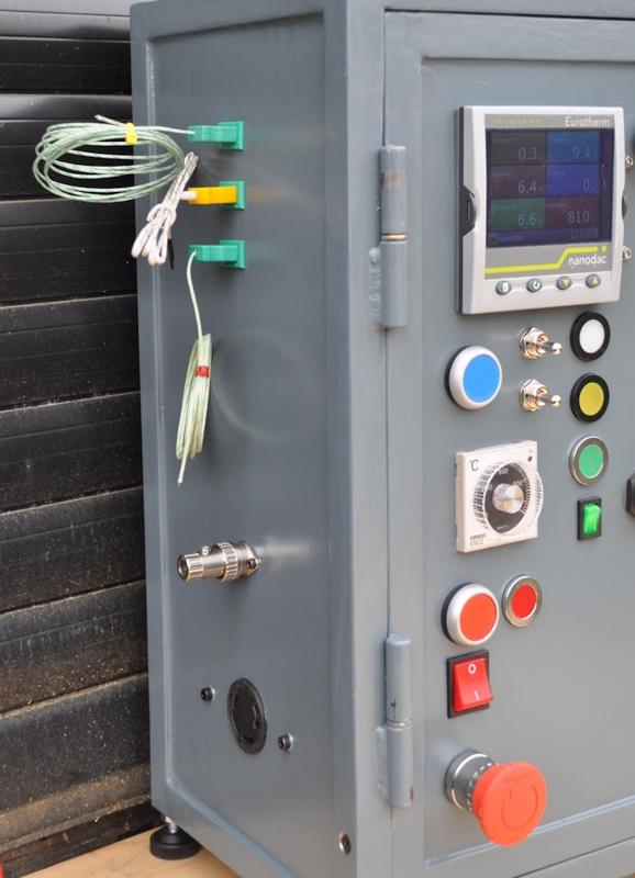
While I've been testing the electronics, I've had a few temporary connections in the side:
2025-02-01-05-temporary-connections_800.jpg


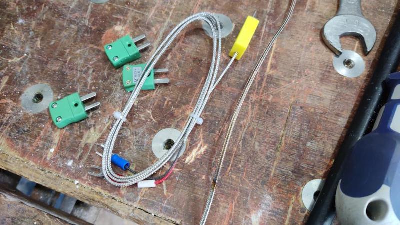
The thermocouples are all K-type, but (as you can probably guess) not rated to the temperatures the chamber will get up to. The middle one has a yellow plug rather than the proper green, but it's still K-type. Americans like to do things differently so they use a different colour scheme and the manufacturer of that thermocouple obviously decided to follow the American convention.

You can also see that there's a plug in the socket for the door interlock. That plug has a shorting link to allow me to pretend that the chamber is present and the door is shut. That's just for testing while I fiddle around with the controller configuration and finish building the chamber.

That's it for now. I have done a bit on the door as well, but I'll write that up when I've made a bit more progress and have something interesting to show.

Overall, I'm really, really pleased with how the control cabinet has come out. The paint job looks reasonably good (although there are a couple of bits on the hinges that need touching up following the big wire-up) and the wiring is a lot neater than I expected it to be. I'm sure it would have been far more sensible (and quick) to buy a box and fit the various switch-gear, but there's something quite satisfying about having made this box from scratch.
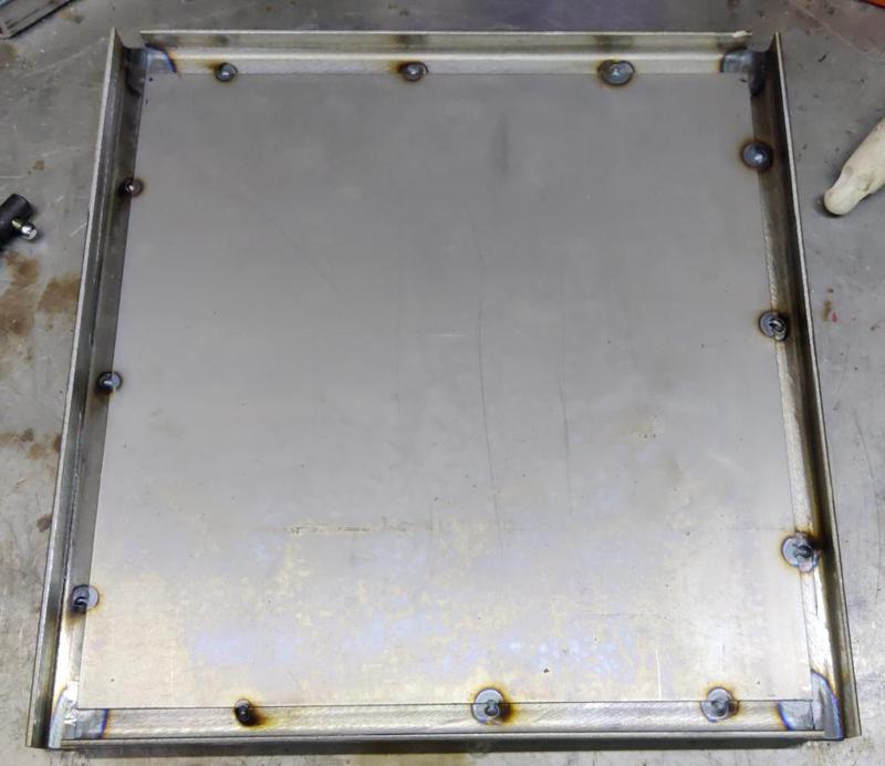
 
To make the door, I started by making a similar frame to the ones I made for the body:

2025-02-02-01-starting-the-door-frame_800.jpg


You may notice that there are some gaps at the ends: that's a result of not having any bits of 20 mm angle iron that were quite long enough. They were long enough to be able to join them, so I figured I'd sort out the gaps later.

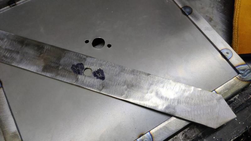
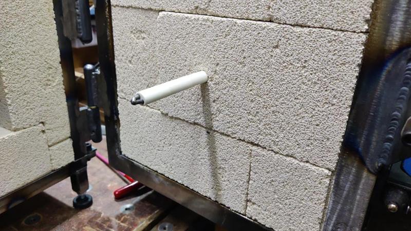
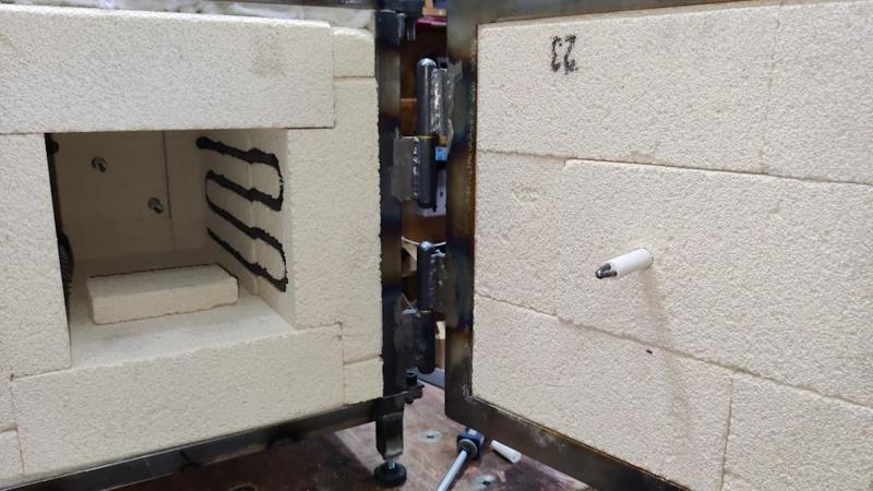
The control cabinet has three thermocouple inputs on the side. The idea of that is that one thermocouple is used for temperature control, one is used for the over temperature safety trip and one is just for monitoring and seeing how the temperature varies across the oven. With two thermocouples coming through holes at the back, it made sense to me that the third one would come through a hole in the door. To that end, I made another 50 mm wide cross bar to go across the front. This time I decided to drill the holes in the sheet before fitting the cross-bar:

2025-02-02-02-cross-piece-and-hole-in-sheet_800.jpg


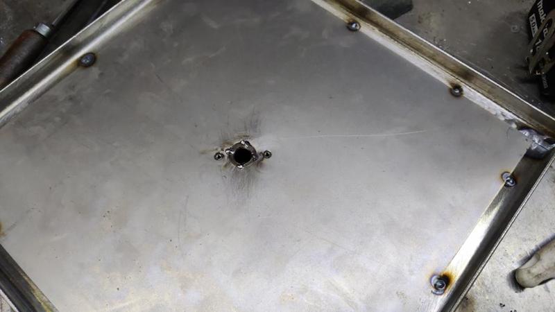
Those holes meant I could tack the sheet to the cross-bar in the middle, which was probably unnecessary, but won't hurt:

2025-02-02-03-tacking-middle-of-sheet_800.jpg


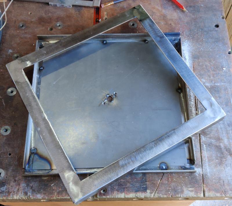
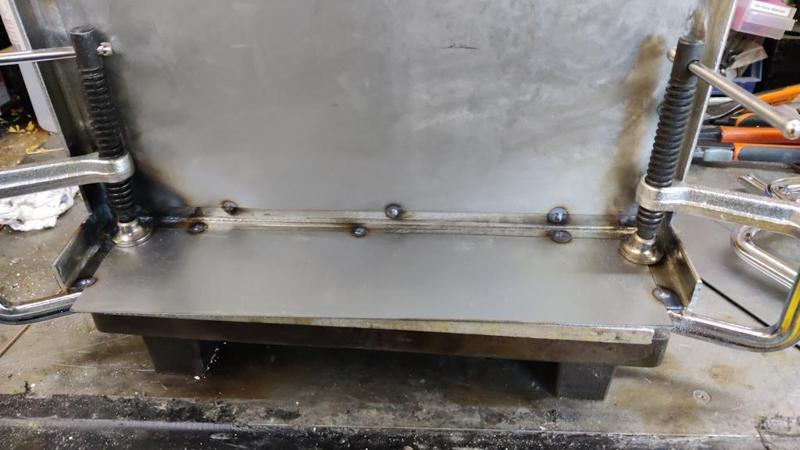
By this point I was almost out of 20 mm angle iron, but I'd also thought that I wanted to support the door bricks a bit better (with more overlap), so I cleaned up (with a flap disc in the angry grinder) some 30 mm angle iron and made a frame out of that:

2025-02-02-04-second-frame_800.jpg


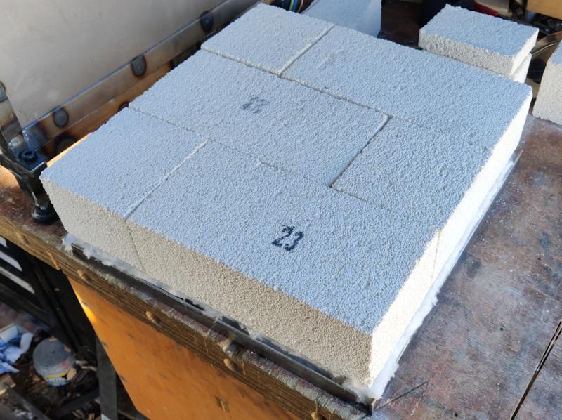
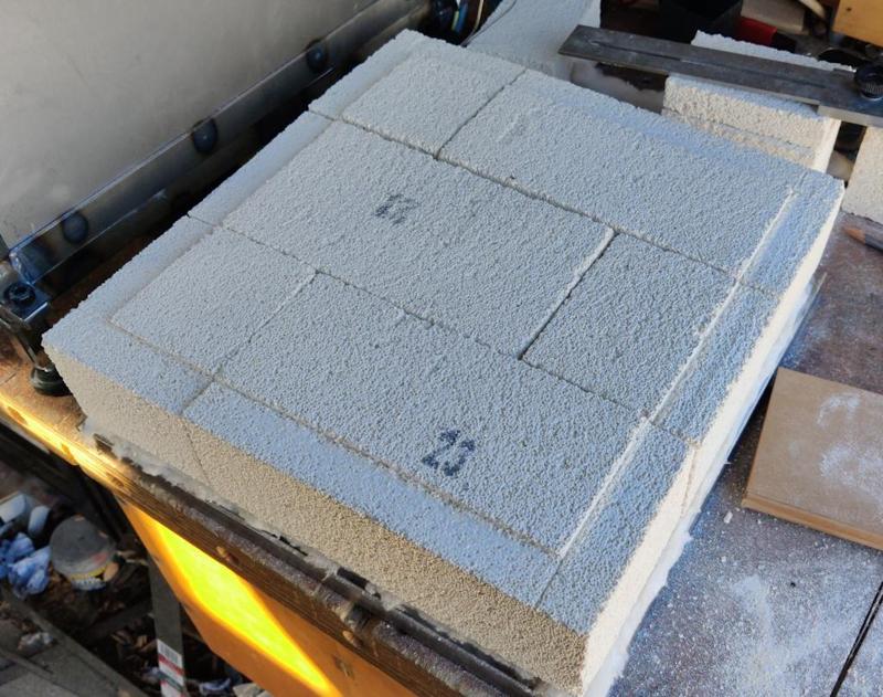
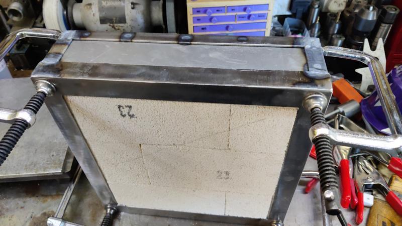
I could then cut some bricks to size and fit them in the first frame (this time not leaving any space around the edges for ceramic fibre blanket as I want the second frame to hold the bricks as firmly as possible):

2025-02-02-05-bricks-cut-to-size_800.jpg


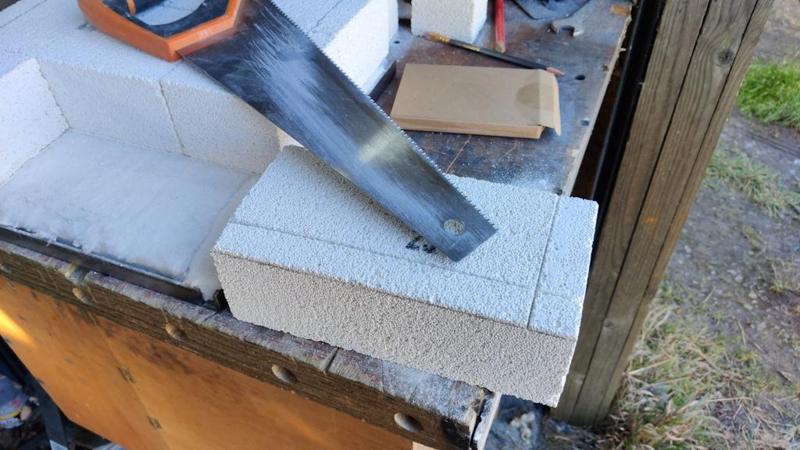
After marking where the second frame would sit, I used a saw to cut a shallow rebate around all the bricks:

2025-02-02-06-cutting-rebate_800.jpg


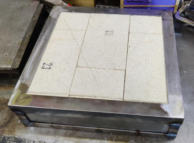
I'd be intending to that with one of these Stanley Surform things (which I inherited but have never used), but I couldn't figure out where I'd stored it, so I just did it carefully with the saw and it seemed to go okay. All the bricks rebated:

2025-02-02-07-bricks-rebated_800.jpg


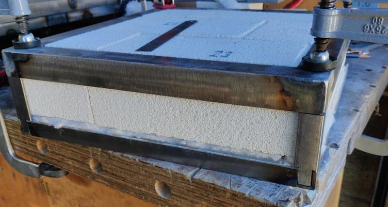
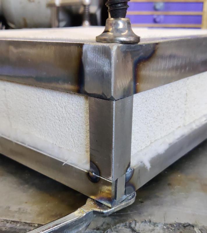
I could then use my small remaining collection of 20 mm angle iron to make the joining pieces. I cut them with a little tongue on the end so that they could fill in that unsightly gap at the same time as forming the remaining sides of the frame:

2025-02-02-08-joining-pieces-clamped-in-place_800.jpg


They then got tacked in place to the first frame only:

2025-02-02-09-tacked-to-lower-piece_800.jpg


After finishing the welding to the first frame, I dismantled it all, cut some bits of sheet steel to size and tacked them in place:

2025-02-02-10-tacking-in-side-sheets_800.jpg


They won't get welded to the other frame (as it'll be impossible to do so. The door then got welded together with bricks in place:

2025-02-02-11-welding-second-frame-on_800.jpg


Unlike the main body of the chamber (which I can dismantle with screws), I decided to just weld the door together. Hopefully it'll be robust and will never need to come apart (the bricks don't have slots cut in them so should be less fragile). If it ever does need to come apart it'll have to be done with a slitting disc in an angle grinder.

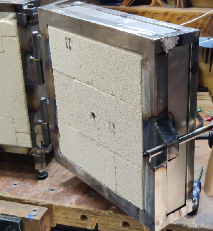
With all the joints welded, the door was complete and ready for mounting:

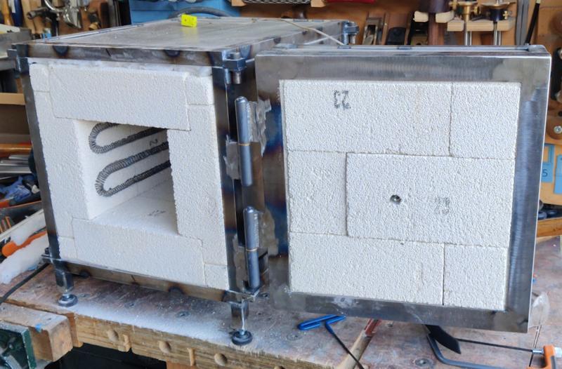
2025-02-02-12-door-complete_800.jpg


To mount the door, I brought the chamber body down to the metalwork end of the garage and clamped the door in place:

2025-02-02-13-door-clamped-in-place_800.jpg


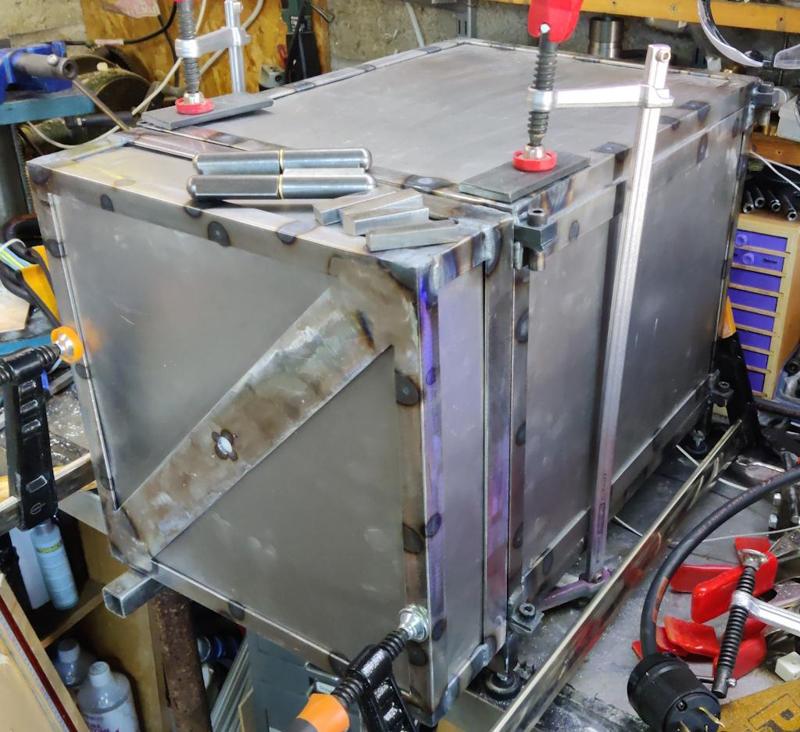
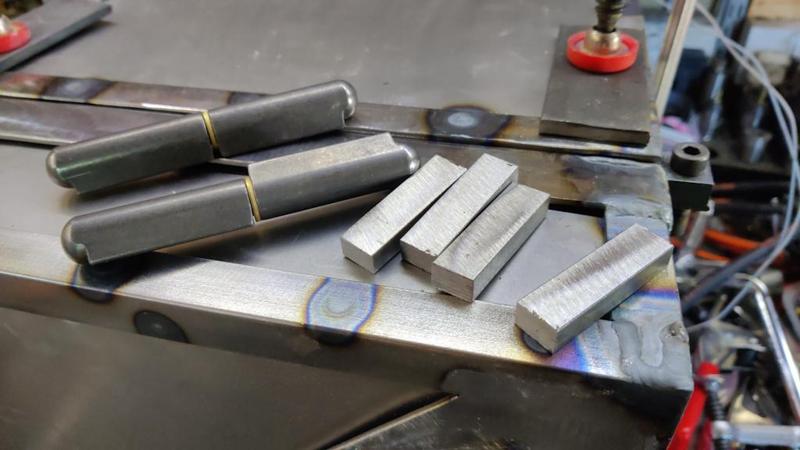
I cut a few 50 mm long bits of steel bar so that I could offset the hinges and avoid any of the rubbing problems I had on the control cabinet:

2025-02-02-14-bullet-hinges-and-blocks_800.jpg


This is where the magnetic hold down clamp I've got really comes into its own as it can hold the block in place while I tack it, despite the fact that it's on the side of the chamber:

2025-02-02-15-magnetic-hold-down_800.jpg


After tacking the first block, I tacked the first half of the bullet hinge in place, then positioned the second block, tacked that and finally tacked the other half of the bullet hinge:

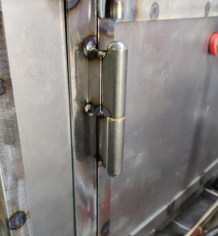
2025-02-02-16-tacked-hinge_800.jpg


The magnetic hold-down was also useful for the second block in each pair:

2025-02-02-17-tacking-lower-hinge_800.jpg


At that point, the door could be unclamped and it opened and closed very easily. I took the door off the chamber and welded the hinge pieces properly to the body (which was a bit awkward given the angles)...

2025-02-02-18-welding-body_800.jpg


... and then did the same with the door (which was a lot easier):

2025-02-02-19-welding-door_800.jpg


I then tried to fit the door and found that the hinges wouldn't go back together. I've never mastered welding stuff without movement and I think this is what happened: the hinges must have moved a bit when I did the final welding. To sort it out, I drilled the bottom door hinge out slightly larger (to give a bit more lateral tolerance) and with that done it went together fairly easily and moves freely:

2025-02-02-20-door-fitted_800.jpg


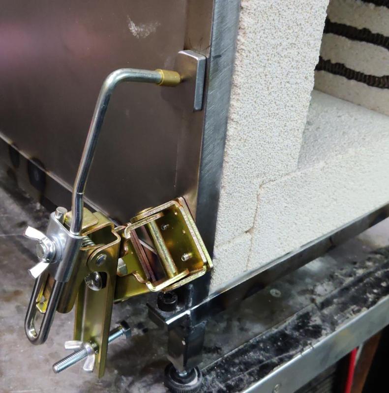
The last big job on the chamber (ignoring painting) is to figure out some sort of latch mechanism to hold the door shut. I haven't really had any thoughts about that yet, so I guess I'll do some web searching during the week.

Another consideration is whether to cut a channel in the door bricks for a fire rope to help seal it, but it feels to me at the moment that the brick-on-brick seal of the door to the chamber will be as good as the brick-on-brick seal elsewhere in the chamber, so I'm currently thinking that I won't bother with the fire rope. Comments / suggestions are welcome as usual.
 
Another consideration is whether to cut a channel in the door bricks for a fire rope to help seal it, but it feels to me at the moment that the brick-on-brick seal of the door to the chamber will be as good as the brick-on-brick seal elsewhere in the chamber, so I'm currently thinking that I won't bother with the fire rope. Comments / suggestions are welcome as usual.
I personally would go for the fire rope seal.
1. You may get some unexpected movement once the assembly is taken up to full temp. that adjusts the door mating characteristics.
2. If at a future date you envision wanting to use an inert gas to reduce oxidisation a good seal would be expedient.
 
Last edited:
I personally would go for the fire rope seal.
1. You may get some unexpected movement once the assembly is taken up to full temp. that adjusts the door mating characteristics.
2. If at a future date you envision wanting to use an inert gas to reduce oxidisation a good seal would be expedient.

I think that's probably sensible, although I'm going to put it off for now. The reason is simply that it'll be a lot easier to add a rope seal later than it would be to remove a rope seal later. I'm certainly expecting some movement as it heats up, but on the first run I'll take it really slowly and keep an eye on things to see how it all moves.

As to inert gases, it sounds like a great thing to be able to do, but I don't really see it as viable. There are plenty of holes in this thing (gaps between the bricks, openings for thermocouples etc) so it would need a pretty continuous stream of gas, which sounds like it could get expensive fast!

Thanks.
 
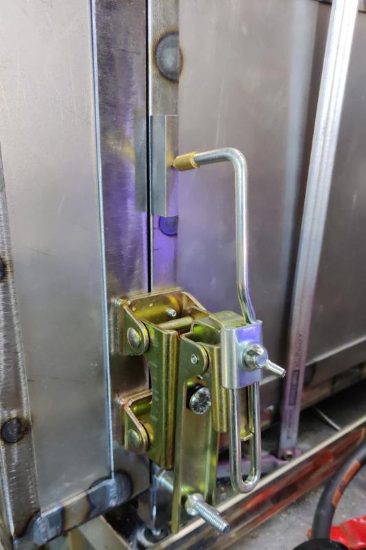
This afternoon I got to work on a latch to hold the door shut. I'd been pondering on lots of options for this and going down a rabbit-hole of methods of making the latch adjustable but still sufficiently rigid. In the end I decided that adjust-ability can come, for now, from a few simple methods. If I need to make the round bits shorter, I'll use a lathe. If I need to make them longer, I'll use washers. If it needs anything more drastic than that, there's always the angle grinder and the welder!

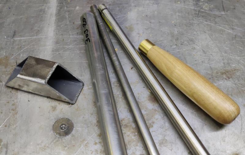
With a (very) vague design in mind, I found some bits of stainless steel and one of the rejected chisel handles I made last year (rejected just because the wood was a bit bland in colour).

2025-02-07-01-bits-for-latch_800.jpg


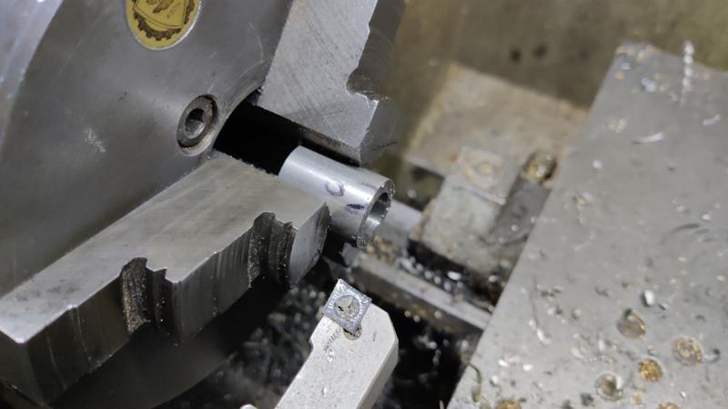
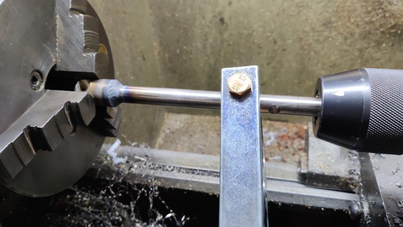
There was then a short sequence involving a few bits of very simple turning...

2025-02-07-02-turning_800.jpg


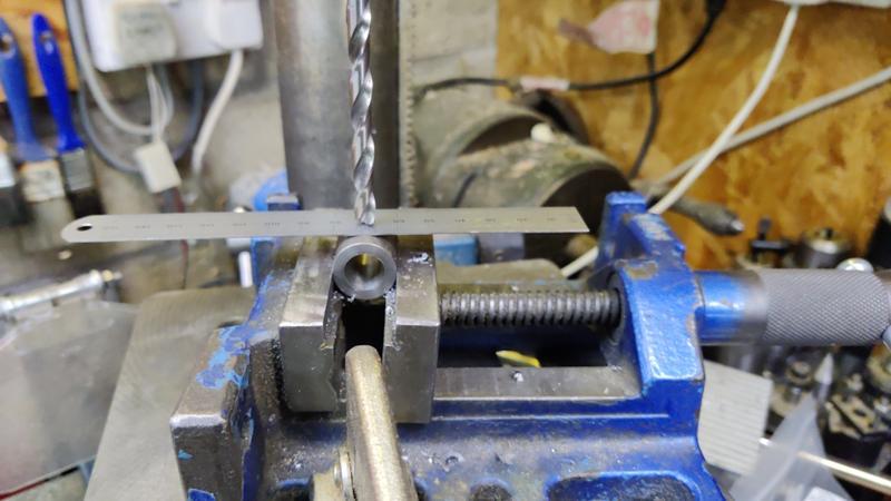
... a few holes made on the pillar drill...

2025-02-07-03-drilling_800.jpg


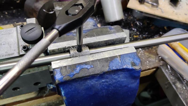
... and some holes tapped:

2025-02-07-04-tapping_800.jpg


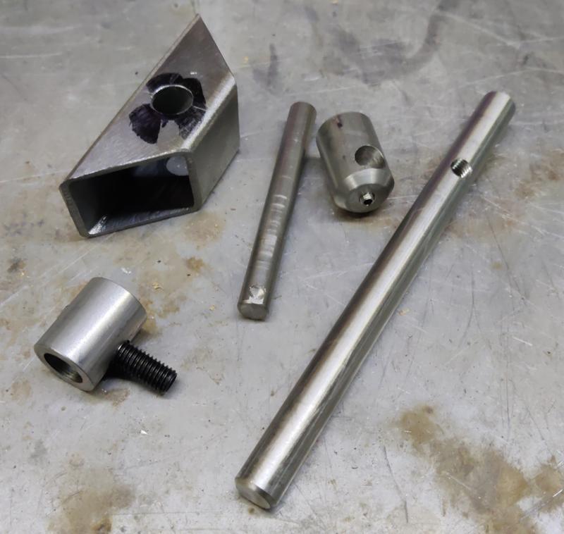
That produced this little pile of machined bits:

2025-02-07-05-machined-bits-for-latch_800.jpg


Most of them are getting joined with screws (so the mechanism can be dismantled and tweaked if necessary), but I wanted the two bits of the main shaft to be held together a bit more permanently (partly as the wider diameter part wasn't long enough to give a good location for a cross-screw), so I decided to weld them. I did that on the lathe, with the gearbox set to 40 rpm and the variable speed drive turned right down (so that it was turning at much, much slower than 40 rpm: probably closer to 2 rpm at a wild guess) - the smooth rotation of the lathe gave me the best chance of a moderately neat weld:

2025-02-07-06-lathe-welding_800.jpg


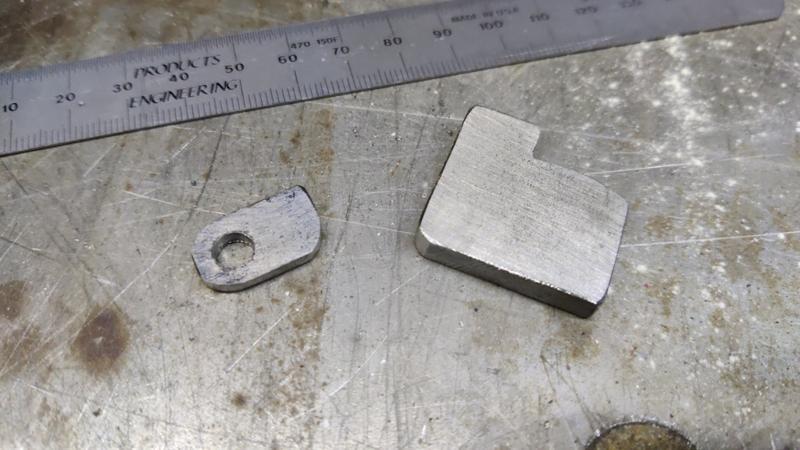
The door bracket (which I'd cut off a spare bit of box section at 45° for purely aesthetic reasons) got tack welded to the door, using the magnetic finger thing to hold it down:

2025-02-07-07-tack-welding-with-mag-holder_800.jpg


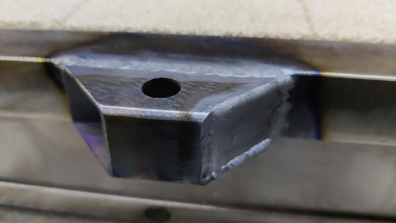
I cut off a spare bit of 3 mm plate that was about the right width and used that to fill in the end of the box section, just on the upper side (the lower side needs to be open to allow access for fitting a grub screw):

2025-02-07-08-tack-welding-plate_800.jpg


I could then weld it more thoroughly, before saying by the traditional welder's incantation of "well, that's not going anywhere":

2025-02-07-09-welded_800.jpg


I needed two more bits for the latch mechanism; they were just made with saw and file (plus the pillar drill for one hole):

2025-02-07-10-other-bits-sawed-and-filed_800.jpg


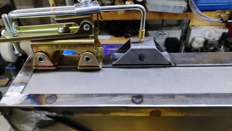
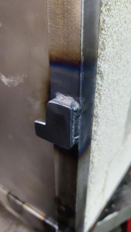
Fitting the latch stop was an example of where the magnetic finger clamp thing really comes into its own:

2025-02-07-11-mag-clamp-really-helpful_800.jpg


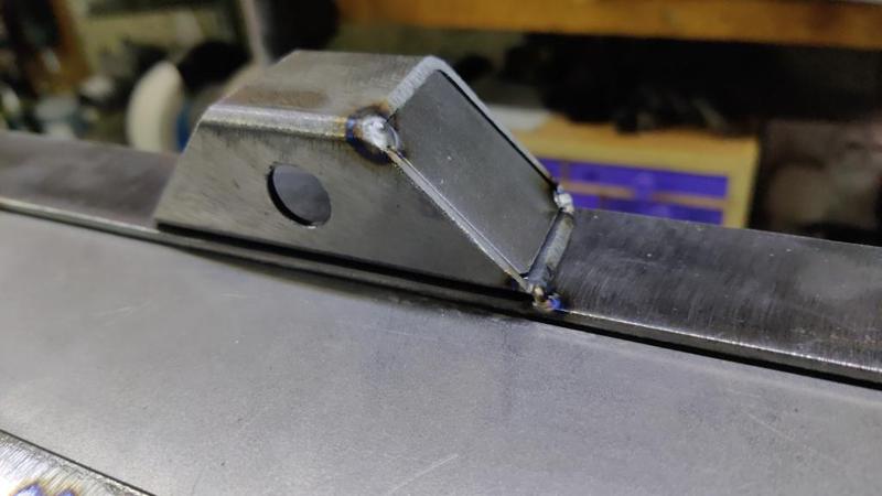
I only bothered to weld two sides of the latch stop as the other sides were awkward. I'm sure two sides will be ample:

2025-02-07-12-welded-two-sides_800.jpg


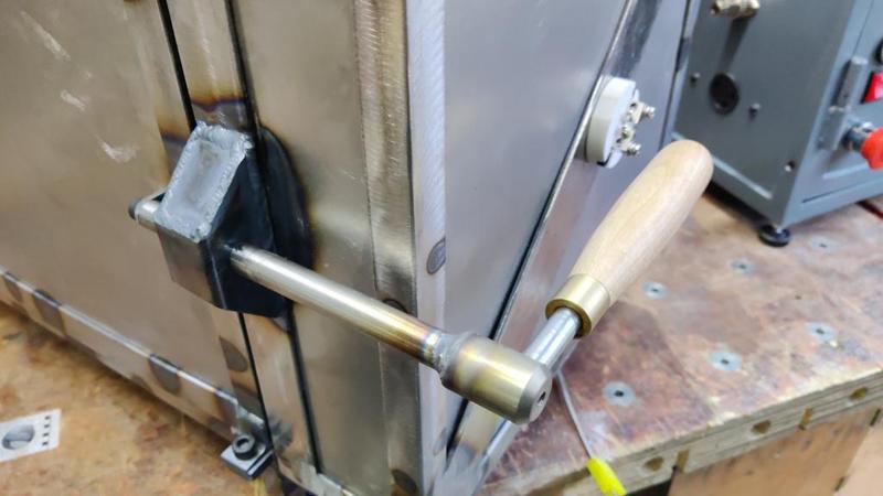
Once all the bits had cooled down, I could assemble the latch:

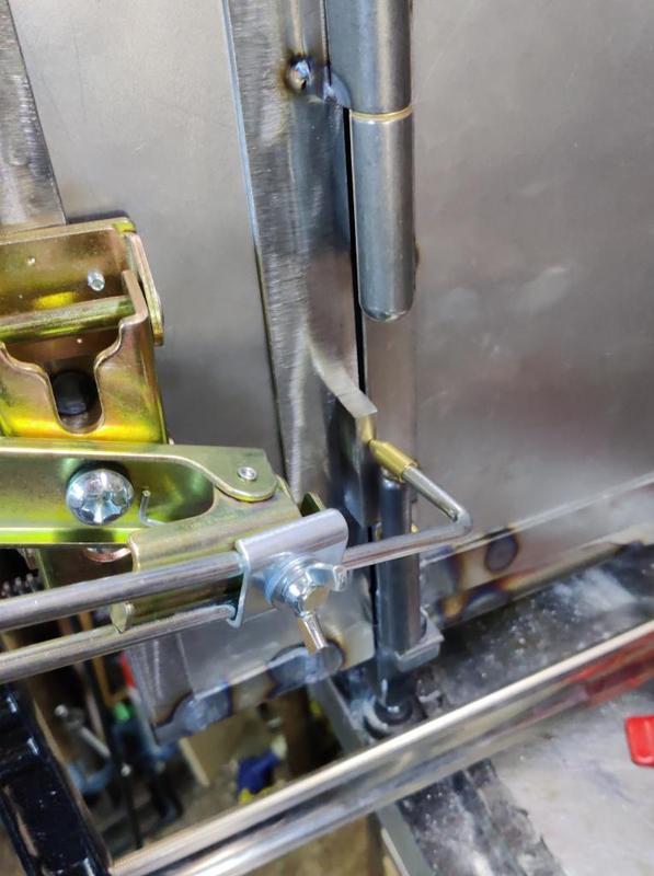
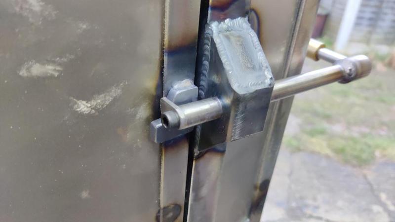
2025-02-07-13-latch-assembled_800.jpg


Rear view:

2025-02-07-14-latch-rear-view_800.jpg


It seems to work well at the moment. It'll be interesting to see what happens when I get it up to temperature. I've no doubt that things are going to move a lot when it gets hot. Steel has a coefficient of thermal expansion (CTE) of about 10 μm/m/°C, meaning for every degree of temperature increase, a metre long bit of steel will grow by 10 μm. I'm sincerely hoping the outside (steel bit) of the thermal chamber won't get anywhere near the temperature of the inside, but if it did then the chamber would grow in length by about 4 mm over an 800°C temperature rise! I've no idea what the CTE of the insulating fire bricks is. Anyway, we'll see what happens; on the first run I intend to bring the temperature up very very slowly.

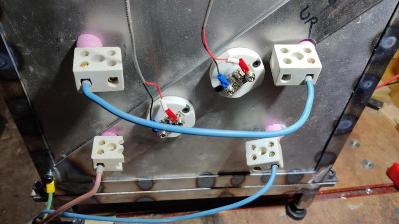
The last remaining major job I can think of at the moment is fitting the door interlock. That shouldn't be especially complicated; I'll probably have a go tomorrow or Sunday. However, in the meantime I do have the little bypass fitting in the side of the control cabinet so I thought I'd wire it all properly and do a little low temperature test. I did some probably slightly iffy wiring on the back...

2025-02-07-15-iffy-wiring_800.jpg


... and then plugged in the control cabinet. Not much happened!

2025-02-07-16-current-too-low_800.jpg


It's putting current through the coil (I can hear the coil buzzing a bit), but hardly any: I think it got up to 3 A. The coil is 20 Ω, so the current should be of the order of 12 A. I think this is probably to do with the playing I was doing (with a lightbulb) as the load a month or two ago. I'd been trying to set it up to limit the current through the lightbulb (which, being only a 40 W bulb, was never going to be very high). I now need to figure out what I did and how to undo it!

I haven't really delved into the EPack programming that much yet. I did a quick experiment changing one setting that I remembered having tweaked compared to how it was set up when I received it, but on re-testing no current flowed at all, so I obviously made it worse! More investigation needed methinks.
 
It's alive, alive!

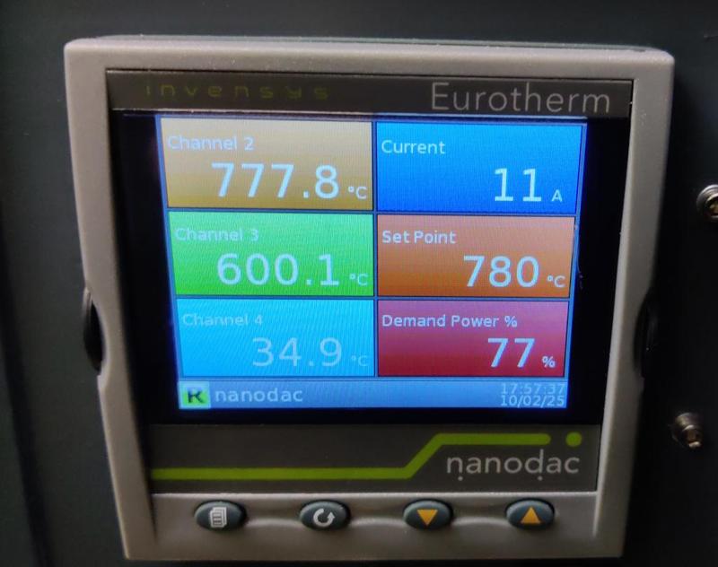
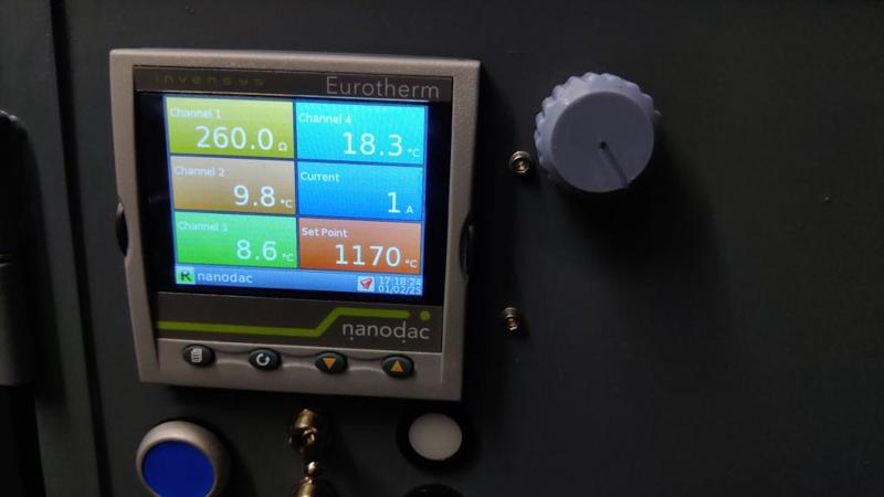
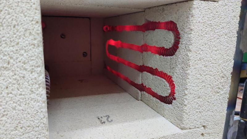
2025-02-08-01-first-heat_800.jpg


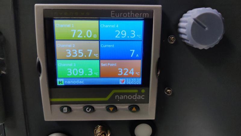
That photo was taken with the chamber at about 100°C and with the EPack configured for 2000 W. So far I've taken it up to a little over 320°C. I set it for 324°C (the potentiometer is a bit sensitive for picking a round number: I perhaps should have gone with a multi-turn one!). There was about 12°C of overshoot (peaking at a reported 336.2°C) and then it looked like it was going to undershoot as well once the temperature started to drop. That's not especially surprising: I doubt the integral bit of the PI controller is well tuned to the chamber. I'll do some digging and see if there are any auto-tune methods (I'd be surprised if there aren't on a controller this fancy).

2025-02-08-02-overshoot_800.jpg


One of the thermocouples on the back of the chamber was giving an invalid reading. I'm not sure why (it might be as simple as my having wired the connections the wrong way round), but I'll wait until everything's cooled down before investigating. Worst case it'll be easy to replace. For the test I just used a low-temperature thermocouple to feed the over-temperature trip (which is okay while I'm standing there watching it like a hawk!).

There seems to be a pretty consistent 25°C-ish difference between the temperature at the back of the chamber (used for control, shown as Channel 2 in the photo above) and that recorded by the door thermocouple (shown as Channel 3 in the photo above). I'd expect some difference (they're measuring the temperature in different places), but I was surprised by the size of the difference, especially since they both started dropping at the same time (vs the door thermocouple just lagging behind the measurement at the back). I suspect there's a calibration issue there somewhere, but I'm not really sure how to calibrate them. I can envisage taking more controlled measurements at relatively low temperatures (less than about 200°C) to check the measurements, but up at the higher levels it could be a lot more difficult.

Anyway, it seems to be fundamentally working, which is great! Nothing "exciting" happened as it heated up to 330°C and the the steel-work all felt cold to the touch. I've turned the heater switch off for now (but left the control power on so the temperature is still monitored) and will let it cool completely. Then I'll have a bit of a rummage inside to see whether anything moved around (e.g. to see if bits fell off the bricks) before heating it up a bit more. I might also increase the set-point to 3 kW, which is about the maximum it'll produce.
 
Still way over my head of course but still fascinating to follow from afar.
I’m trying to imagine quite what you are going to put in there. Is it going to work like a min forge? Heat metal hot enough so you can bash it into shape?
 
This is great Dr. Al, as you say to see it come alive must have been a relief. Does it need more tweeking before you start using it.
 
Still way over my head of course but still fascinating to follow from afar.
I’m trying to imagine quite what you are going to put in there. Is it going to work like a min forge? Heat metal hot enough so you can bash it into shape?

I don't think (but I'm not sure) that it'll be quite hot enough for that. According to wikipedia, the forging temperature for carbon steel is 1230°C, which is getting far too close to the rating of the components in the oven (max is 1260°C if memory serves me correctly).

What it'll be used for is basically two things:
  1. Softening ("annealing") hardened steel by heating it up to red hot and then bringing the temperature back down extremely slowly. This could be useful for turning (e.g.) an old file (which will be hardened) into something else
  2. Hardening carbon steel by heating it up to red hot, holding it there for a bit and then the part will be quenched in something (oil, water or brine) to cool it down rapidly. I may then also use the chamber for tempering.
So basically, it's for making tools. I've done this in the past with a blowtorch and made quite a few plane blades and such-like. For small tools like plough plane blades it works really well, but as the tool size gets bigger it reaches a point where the parts cool down (from the cool ambient air) too quickly and you just can't get enough heat in with the blowtorch to compensate (or if you can, it takes a long time of standing holding a blowtorch!). With the oven, the ambient temperature will be high so it should be easier. It won't be as quick, but it'll be much more controlled and the time will be spent waiting for an oven to warm up rather than standing/squatting holding a blowtorch.
For bigger things like plane blades, blowtorch heat (which tends to result in the blade being hot in places and cool elsewhere) can cause quite a lot of shape distortion; in theory the chamber should be better. It'll also allow temperature ramps and things like that, which is required for hardening some more exotic materials (e.g. some stainless steels).
This is great Dr. Al, as you say to see it come alive must have been a relief. Does it need more tweeking before you start using it.

I need to turn the current up to 100% (it's running at about 70% at the moment) and I also need to (in stages) gradually bring the temperature all the way up to make sure nothing untoward happens. However, all being well I'll do some sort of heat treatment this weekend as a practice: possibly annealing an old file as that's something I've never done before.
 
After getting back from a long lunch with some friends, I went to check on the chamber. It had been at 210°C when I turned it off and, 2½ hours later, it had dropped to 100°C, which seemed pretty good to me (i.e. the insulation can't be too bad if it holds that much heat for that long).

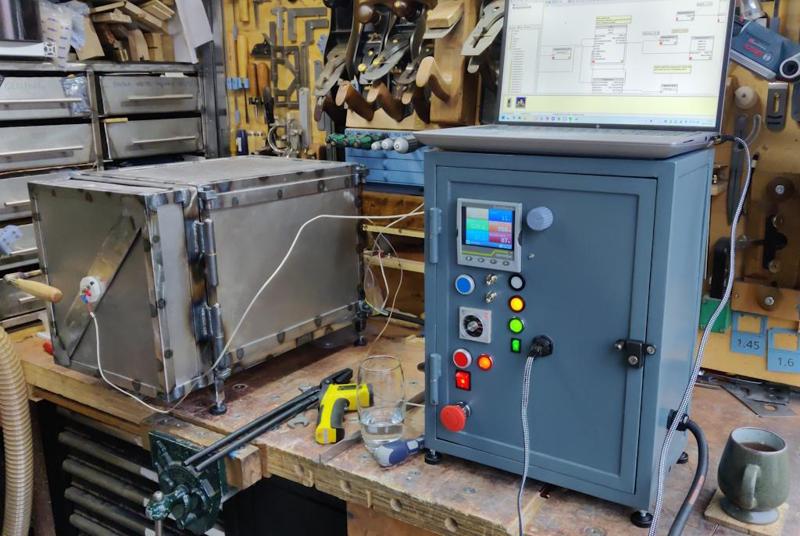
Rather than carting the control cabinet up and down the garden path, I decided to take the laptop out to the garage to do some experimenting with settings:

2025-02-08-03-laptop-with-chamber_800.jpg


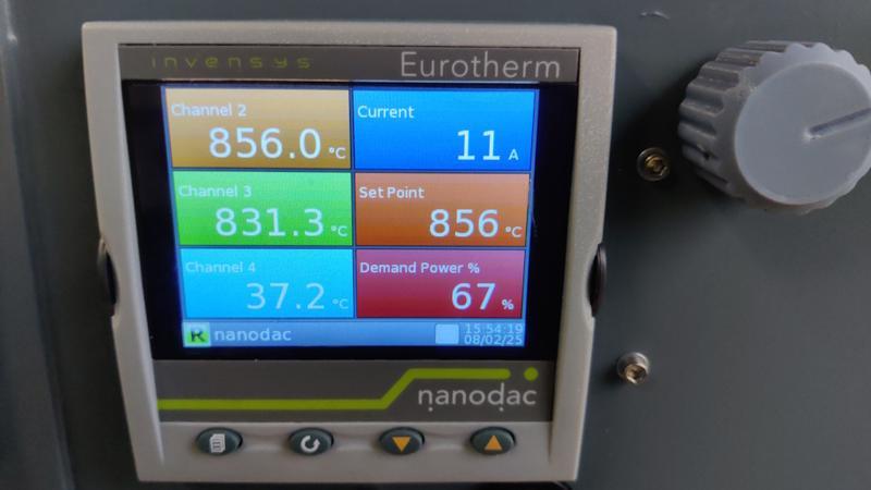
I changed the EPack power up to 3 kW, tweaked the display settings of the Nanodac so it showed the demand to the EPack (because I was interested) and also ran the auto-tune algorithm with the set-point configured at 570°C. After that, I thought I'd wind it up a bit hotter and see how it went. The auto-tune obviously worked as there was very little overshoot on its way up to the (rather random) target of 856°C:

2025-02-08-04-hot-hot-hot_800.jpg


I was standing there expecting to here lots of little noises (creaks etc) as things moved in the chamber, but it was surprisingly uneventful really. Nothing happened apart from it getting very hot! I opened the door and chucked an old file in:

2025-02-08-05-file-in-the-chamber_800.jpg


While the door was open, I also pointed a cheap infrared temperature sensor at the bricks and it reported something in the region of 860°C, so at least that tells me the thermocouples can't be that far off!

Over the next hour or two, I gradually reduced the temperature down to about 450°C and then turned the chamber off. I doubt that'll be a slow enough rate of cooling to anneal the file I put in there, but I didn't have the patience to turn the dial down any slower. In due course I'll set up a program (controlled by one of the switches) to do a really slow rate of change of temperature automatically. That will be useful when I want to anneal something.

For now, I'll leave the chamber to fully cool down overnight. It'll be interesting to see how hard the file is in the morning, but I won't be disappointed if it's still a bit hard. Tomorrow I'm going to fit the door interlock as the first job and then do some investigation into what's going on with the errant temperature sensor.

For today though, I'm really happy with how it all went. There's still lots to do, including taking an angle grinder to the remaining sharp corners, painting it and putting a bit more effort into the Nanodac programming, but it feels like today was a major milestone.
 
Dr. B. I am in awe of your cumulative skills. I used to run a constant temperature room, with both ovens and chromatographs (which were all elderly and needed coaxing to work properly) so I have a passing acquaintance with what you have achieved on these pages. Nice one.
 
I've just caught up. Wow. That really is very impressive, Al. Well done.
 
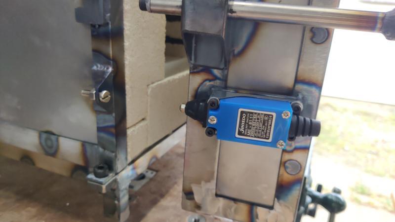
Fitting the door interlock was quite straightforward. The first job was to roughly saw a bit of 6 mm plate to size and then drill and tap four M4 holes in the corners. That got tacked to the side of the door...

2025-02-09-01-interlock-plate_800.jpg


... and then welded along each short edge:

2025-02-09-02-welded-plate_800.jpg


For the other half, an off-cut of angle gained an M6 tapped hole and then got hacksawed to remove the sharp corners. That got welded onto the side of the chamber body:

2025-02-09-03-interlock-angle_800.jpg


While the welded bits were cooling down I did a bit of investigation into the faulty thermocouple. The cable was a bit discoloured, so I suspect that I inadvertently laid it over something that I'd recently welded and that caused it to absorb some heat. Anyway, I had a spare thermocouple, so I nicked the cable off that one and, while I was at it, I replaced all the cheap American-coloured connectors with decent quality green ones:

2025-02-09-04-replacing-thermocouple-cable_800.jpg


Once everything had cooled down, I could fit the interlock:

2025-02-09-05-interlock-fitted_800.jpg


It's fitted to the door (rather than the body) so that the cable follows the same route as the door thermocouple, which seemed to make more sense to me: cables originate from the back and front of the chamber rather than having several cables from the back, a thermocouple cable from the front and the interlock cable from the far side.

I haven't wired it up yet as I don't have any suitable cable; I'll order some as soon as I get round to it.

Next up was another test with all the thermocouples connected:

2025-02-09-06-running-with-three-thermocouples_800.jpg


The cable replacement seems to have done the trick: everything worked properly.

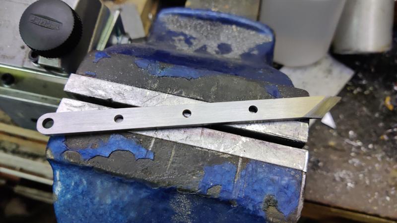
I wanted to time how long it would take for the chamber to get up to temperature and I figured that if I were doing that, I'd put something in it to heat treat. To that end, I grabbed a bit of 3 mm × 10 mm gauge plate out of the drawer and attacked it with a hacksaw...

2025-02-09-07-hacksawed-gauge-plate_800.jpg


... and then with the pillar drill and a file:

2025-02-09-08-drilled-gauge-plate_800.jpg


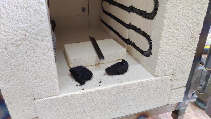
I put it in the chamber, along with a couple of bits of charcoal. The book I use as a reference for heat treatment suggests this as one possible way to reduce the build-up of scale during heat treatment. I usually use boric acid (or just accept the clean-up work), but I thought I'd try the charcoal.

2025-02-09-09-with-charcoal-bits_800.jpg


This little blade is small enough that it would be quite easy to heat treat with a blow torch (especially having filed a rough bevel as the working end is very thin and doesn't need much of a "soak" at temperature), but it seemed as good a choice as any for something to use to test the chamber.

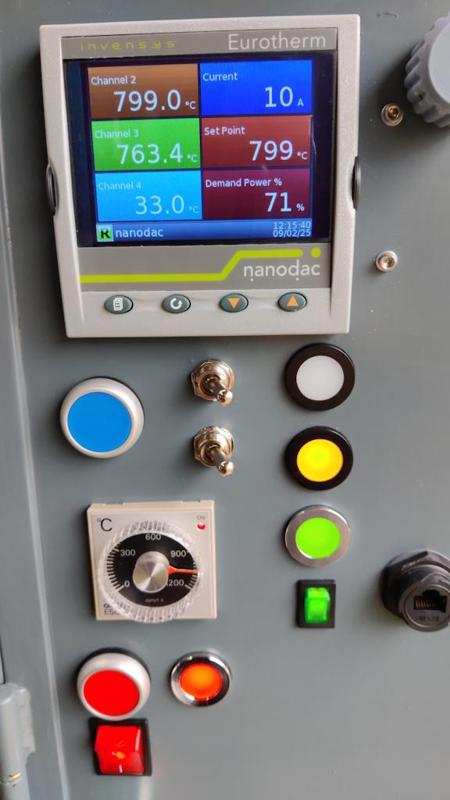
I started a timer and then started the chamber running. It took 7 minutes to get to 300°C (so it's considerably faster than our domestic oven, which is unsurprising given how much smaller the cavity is); it slowed down towards the end (as the control loop started to do its thing), finally settling at the target temperature after 28 minutes:

2025-02-09-10-28-minute-heat-up_800.jpg


The label on the packet the gauge plate came in suggested to heat to between 780°C and 800°C, so I set the set-point to the upper end to account for the alleged temperature gradient across the oven. I decided to let it have a long (20 minutes) soak at temperature. The rule of thumb is an hour per 25 mm of thickness; this piece is only 3 mm thick, so only needs 7 minutes (and less than that at the tip of course), but I thought I'd make sure it had plenty of time. If I were heat treating it with a blow torch, I only would have given it a minute or so (out of impatience), but the chamber makes it easy to leave it a bit longer.

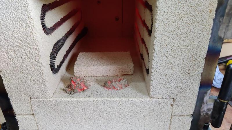
When it had completed the soak time, I opened the door, grabbed the part (with tongs, obviously!) and dunked it in vegetable oil. The oil container I have in the garage was too shallow to submerge the entire part (I'll get a replacement at some point), but the tip's the only important bit really. This is what the bits of charcoal looked like after the cycle:

2025-02-09-11-remaining-charcoal_800.jpg


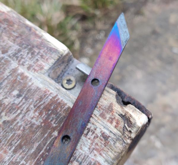
After cleaning all the scale off (the charcoal didn't really help), I then (somewhat optimistically, I'll admit) decided to use the chamber to temper the part. For that, it needs to be heated to about 200–220°C for the same 7 minute soak. I opened the chamber door and went had lunch, then closed the door and left it a bit longer until it was staying consistently below 220°C. I chucked the part in and left it for about quarter of an hour. When I opened the door and pulled it out, the part had gone a tasteful shade of blue:

2025-02-09-12-over-tempered_800.jpg


That colour means that it was substantially overheated (probably to about 300°C instead of 220°C). It's possible that the thermocouples are dramatically mis-reading, but I suspect its more likely that the insulating fire bricks were quite a lot hotter than the air temperature (as they cooled slower); the thermocouples were reading the air temperature, but the part was sitting on the brick so would have conducted the heat directly from the brick.

The only way to deal with that is to re-harden and have another go, so I heated the chamber back up to 780°C, quenched in oil again and I've now left everything to cool down. By this time tomorrow it should be fully cool, so I can have another go at tempering. That should also give me a chance to see how good the temperature readings are (as it'll be cool enough that I can stick an oven thermometer in the chamber as well as being able to gauge temperature from the colour of the steel). I'll probably try with a few off-cuts of (unhardened) steel first so I don't have to go round the full hardening cycle again.
 
After cleaning all the scale off (the charcoal didn't really help), I then (somewhat optimistically, I'll admit) decided to use the chamber to temper the part. For that, it needs to be heated to about 200–220°C for the same 7 minute soak. I opened the chamber door and went had lunch, then closed the door and left it a bit longer until it was staying consistently below 220°C.
I don't know the answer, but is it a bad thing to leave the kiln to cool with the door open? I did raku firing many years ago and sometimes used electric kilns, and remember closing the door asap to avoid too much thermal shock on the elements. Or, I could be wrong and we closed the door to avoid heat loss before putting the next piece of work in. That was about four decades ago!
 
I don't know the answer, but is it a bad thing to leave the kiln to cool with the door open? I did raku firing many years ago and sometimes used electric kilns, and remember closing the door asap to avoid too much thermal shock on the elements. Or, I could be wrong and we closed the door to avoid heat loss before putting the next piece of work in. That was about four decades ago!

You might be right. Either way, I think I've shown it's not really viable to cool the chamber relatively rapidly and expect it to be at the new target temperature (unless you wait a long, long time for the bricks to cool). In future I think I'll just use it at a given temperature (or at least in a narrow-ish temperature band) and then let it cool naturally over a long time (12 hours plus) before using at a lower temperature.
 
... a few holes made on the pillar drill...

2025-02-07-03-drilling_800.jpg


...
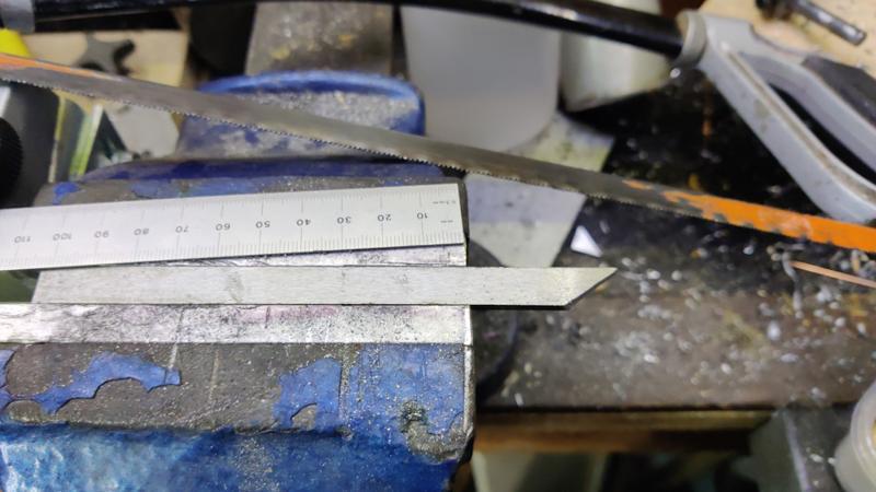
Fascinating thread. I was intrigued by the photo above. Is the use of the ruler a way of ensuring you are drilling perpendicular to the pipe? If so that’s a new trick I didn’t know. Thanks
 
Fascinating thread. I was intrigued by the photo above. Is the use of the ruler a way of ensuring you are drilling perpendicular to the pipe? If so that’s a new trick I didn’t know. Thanks
Exactly that. When the bit pinches the rule to the work, it'll be tangential to any round object in the vice (assuming you're close enough to horizontal that the tip geometry doesn't have an effect).

If the rule is horizontal, the bit is over the centre and the hole will go through the middle. The longer the rule, the easier it is to see whether it's horizontal, but a 150 mm rule gives plenty of accuracy .
 
... and that's just one reason why detailed WIP threads such as this one from the good doctor are so worthwhile - even if you are never going to make a heat treatment oven, it's good to watch along, and learn from his experience.
 
Thanks Andy. It's nice to know the thread is useful. Some of my non-woodworking threads (and some of my woodworking ones too) can feel a bit like shouting into the void so it's always nice to know people read and enjoy.

It's probably worth noting that in this application (and many others), I would use a spotting drill. The photo I shared was me being lazy: I had put the long drill bit in to make sure there was clearance to use it for the hole, so I left it there while making sure the vice was in the right place. I then swapped to a spotting drill to start the hole and then back to the twist drill to finish.

Spotting drills are one of the best things I ever discovered for making accurate holes. I used to use centre drills to start holes (especially on the lathe), but since I got a load of spotting drills, they're all I use and centre drills are only ever used for making centre holes for supporting work on the lathe.

Spotting drills are by far the best thing to use when you want the hole to start in the right place (whether you're defining the right place as "straight down from the chuck centre" when the work is clamped firmly or "into the centre of that centre punch mark" when the vice is loose). If I'm drilling anything metal (and sometimes if I'm drilling other materials too), a spotting drill is pretty much always the first thing I use (whether it be pillar drill, lathe, milling machine or even the Makita cordless thing).

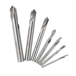
In case you're not familiar, this is what I mean by a spotting drill (example link here, but that's just the first one I found, not a specific recommendation):

1739206386054.png

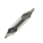
Compare them to a lathe centre drill:

1739206435769.png

At least half of my centre drills have one of the flimsy tips broken off!
 
Whenever, if ever, I need to drill a hole in circular tube I can but hope that I will remember that ruler trick.
 
Whenever, if ever, I need to drill a hole in circular tube I can but hope that I will remember that ruler trick.

Not just tube: any round bar. It would, in theory, also work for a sphere, but you'd have to test the rule in two orientations.
 
I did a few tests this evening, using various different thermocouples (including a low temperature rated one for some low temperature testing). It was quite interesting. The main thing I've learnt so far is that the temperature varies quite a bit and, in particular, the insulating fire bricks insulate the thermocouples from the chamber's ambient temperature.

I know that sounds a bit obvious (insulating fire bricks are insulating, who knew?!), but I didn't expect the effect to be as pronounced. The thermocouples as designed stick out into the chamber by about 5 mm, so the entirety of the welded blob on the end (where the two metals join) is in the cavity rather than being surrounded by brick. I thought that would mean they measure the air temperature quite effectively, but look at these two measurements (Channel 1 and Channel 2):

2025-02-10-01-big-temperature-difference_800.jpg


Channel 2 is one of the thermocouples at the back, which sticks out about 5 mm and looks a bit like this earlier picture of the door thermocouple:

2025-02-10-02-previous-thermocouple_800.jpg


In that test, the door thermocouple was replaced by a new (uncut) one looking like this:

2025-02-10-03-test-thermocouple_800.jpg


For that to account for that much of a temperature difference was quite surprising to me (especially considering that the door one previously under-read relative to the one at the back by about 20°). I'd guess that this would explain why the attempt at tempering went wrong: the thermocouples were under-reading by enough to make a mess of any measurement accuracy.

I'll replace all the thermocouples with ones that stick out a bit more (although not as much as the test one shown in the last photo above, as that'll probably get in the way) and do some more testing.
 
Thanks Andy. It's nice to know the thread is useful. Some of my non-woodworking threads (and some of my woodworking ones too) can feel a bit like shouting into the void so it's always nice to know people read and enjoy.

It's probably worth noting that in this application (and many others), I would use a spotting drill. The photo I shared was me being lazy: I had put the long drill bit in to make sure there was clearance to use it for the hole, so I left it there while making sure the vice was in the right place. I then swapped to a spotting drill to start the hole and then back to the twist drill to finish.

Spotting drills are one of the best things I ever discovered for making accurate holes. I used to use centre drills to start holes (especially on the lathe), but since I got a load of spotting drills, they're all I use and centre drills are only ever used for making centre holes for supporting work on the lathe.

Spotting drills are by far the best thing to use when you want the hole to start in the right place (whether you're defining the right place as "straight down from the chuck centre" when the work is clamped firmly or "into the centre of that centre punch mark" when the vice is loose). If I'm drilling anything metal (and sometimes if I'm drilling other materials too), a spotting drill is pretty much always the first thing I use (whether it be pillar drill, lathe, milling machine or even the Makita cordless thing).

In case you're not familiar, this is what I mean by a spotting drill (example link here, but that's just the first one I found, not a specific recommendation):

View attachment 31985

Compare them to a lathe centre drill:

View attachment 31986

At least half of my centre drills have one of the flimsy tips broken off!
Thanks Al. I do find it a fascinating read. Whilst I don’t ever expect to be building a heat treatment oven I am interested in how you are doing it and picking up useful tips along the way. Thank you.
 
Advice on the MIG welding forum suggested that the thermocouples should stick out at least 50 mm or ten times the diameter of the tip. The tip diameter is 5 mm, so that tallies nicely! I replaced all three thermocouples; they all now protrude about 55 mm into the chamber:

2025-02-13-01-extended-all-thermocouples_800.jpg


I haven't trimmed the excess yet, but they'll all have to come back out soon as I need to paint the chamber.

2025-02-13-02-not-trimmed-yet_800.jpg


The eagle-eyed among you will have notice that I've now wired up the door interlock, which should make the whole thing a lot safer.

With that done, the temperature seems much more consistent over the cavity (i.e. the thermocouples at the rear agree with the ones at the front). I also used a separate low-temperature thermocouple for some tests at around 200°C and that thermocouple agreed as well, so I think the extension of the thermocouples was well worth it. Tempering the little test blade produced a much better colour this time, although it was hard to photograph and I don't think the image shows the colour that well:

2025-02-13-03-better-colour_800.jpg


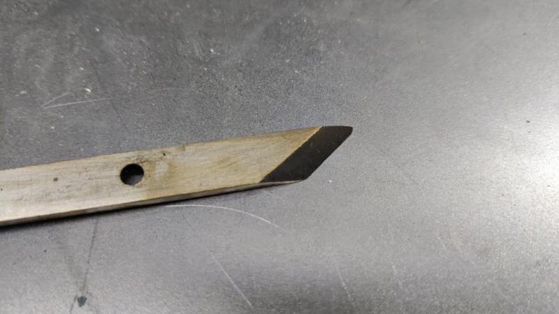
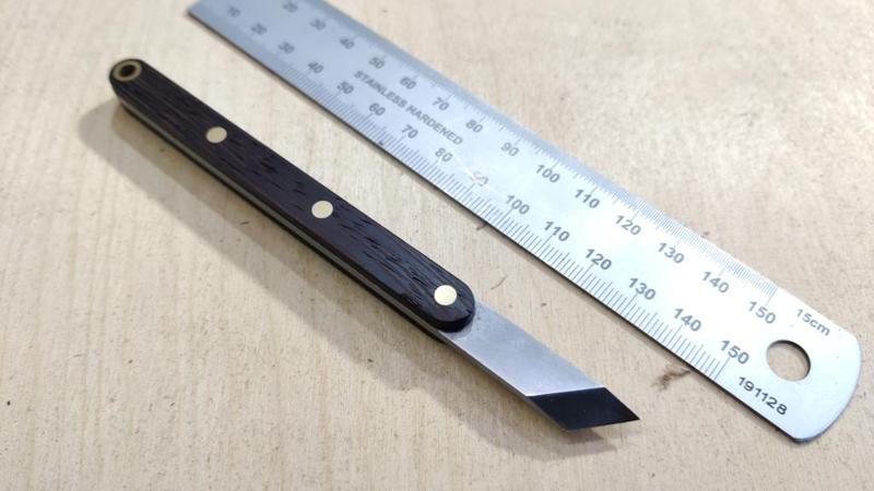
With the blade tempered, I could give it a bit of TLC in the form of some rubbing on wet-and-dry, some sharpening and the addition (with epoxy) of some wenge scales. With that done and a coat of Mike's Magic Mix applied, the marking knife is finished:

2025-02-13-04-finished-marking-knife_800.jpg


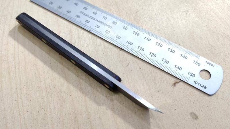
Side view:

2025-02-13-05-side-view_800.jpg


This knife is well within the realms of things that could be done with just a blowtorch rather than requiring a big and complicated heat treatment oven, but I wanted to do something to test the chamber and this was a nice quick and simple project to use for the trial.
 
Something occurred to me last night as I was trying to get to sleep, sad innit?
If you were to apply a blow torch, or similar to heat treat (temper, is that the right term?) that piece of steel you would only need to heat the inch or so that will be shaped and sharpened. By using your oven you are heating the whole piece. I am guessing that tempering the whole piece does not do any harm but it does seem a bit wasteful and perhaps an inefficient use of energy.
Or is this the way it would be done in the factory too?
 
Something occurred to me last night as I was trying to get to sleep, sad innit?
If you were to apply a blow torch, or similar to heat treat (temper, is that the right term?) that piece of steel you would only need to heat the inch or so that will be shaped and sharpened. By using your oven you are heating the whole piece. I am guessing that tempering the whole piece does not do any harm but it does seem a bit wasteful and perhaps an inefficient use of energy.
Or is this the way it would be done in the factory too?
You're absolutely right that you only need to heat the bit that's cutting. There are advantages and disadvantages to that. Drill bits (to pick a random example) are typically hardened at the cutting end but not at the shank as the softer shank makes it easier to grip them in a chuck. That can also be achieved to some extent by hardening† the whole thing, then tempering‡ with more heat applied to the shank (so the shank loses more of its hardness than the tip). In a forge (which is likely to be less insulated than my heat treatment oven), you could chuck the tip of the part in the coals while leaving the shank hanging out.

As you say, heating it all arguably uses more energy. However, for me I don't think the difference will be that great, particularly with large tools. If I heat with a blowtorch, I'm constantly fighting the fact that the air around the part is at (say) 10°C and if I move the blowtorch away for a couple of seconds I lose a lot of the heat I've put into it (that can be mitigated a bit by having some loose fire bricks around the part when blasting it with the torch). It can take quite a long time to heat a big part up with a blowtorch and you can get through a lot of gas! With the chamber, I'm heating all the air in the cavity (which obviously needs a lot of energy), but the cavity is insulated (by the bricks) so I'm spending less energy heating all the air in my garage. As to which ends up being more efficient... I've no idea, but it probably depends on the size of the part. For something the size of that little marking knife, I think I'd probably still just use a blowtorch under normal circumstances (i.e. when not trying to test an oven!). For something the size of a plane blade, I'd use the oven as it'd be a lot easier to ensure that the entire length of the cutting edge will be heated to the same temperature (and it also saves me a lot of time standing or squatting holding a blowtorch and trying to get enough heat into a part). I don't heat treat parts often enough for energy efficiency to be a primary concern really.

The other consideration is distortion. If you take a piece of steel (particularly one that has some shape to it - i.e. not just a cuboid) and heat one end more than the other before plunging it into a quench bath (oil or water usually), it'll change shape as it heats and cools unevenly. That'll still happen if you heat the whole thing evenly, but the effect is much smaller than with one end much hotter than t'other. That's a big advantage of a heat treatment oven over a blowtorch.


You mentioned "temper, is that the right term?". Some clarification to help:

† Hardening is typically a process of bringing the part or all of the tool up to a cherry red heat (780°C ish, depending on steel grade), holding it at that temperature for a bit (an hour per 25 mm of thickness), then cooling it rapidly by dunking it in oil or water. That makes it very hard (often referred to as "glass hard"), but also brittle: it would be likely to snap if you tried to cut with it.

‡ Tempering is a process of reheating the hardened part to make it tougher (less brittle) at the expense of a little bit of hardness. That typically involves heating the part up to a straw colour (220°C ish, depending on the type of tool you're making), holding at that temperature for a bit (as before), then either quenching or letting it cool naturally.

Either of those can be done with a blowtorch or with a heat treatment oven. Tempering can also be done with a domestic oven (or even a deep fat fryer - it doesn't have to be done in air) if the temperature control of said appliance is good enough.

Does that all make sense?
 
Thank you for taking the time, yes that helps my ageing brain understand a lot better. Everyday a school day eh?
 
Back
Top