• Hi all and welcome to TheWoodHaven2 brought into the 21st Century, kicking and screaming! We all have Alasdair to thank for the vast bulk of the heavy lifting to get us here, no more so than me because he's taken away a huge burden of responsibility from my shoulders and brought us to this new shiny home, with all your previous content (hopefully) still intact! Please peruse and feed back. There is still plenty to do, like changing the colour scheme, adding the banner graphic, tweaking the odd setting here and there so I have added a new thread in the 'Technical Issues, Bugs and Feature Requests' forum for you to add any issues you find, any missing settings or just anything you'd like to see added/removed from the feature set that Xenforo offers. We will get to everything over the coming weeks so please be patient, but add anything at all to the thread I mention above and we promise to get to them over the next few days/weeks/months. In the meantime, please enjoy!

Heat Treatment Oven

Dr.Al

Old Oak
Joined
Dec 31, 2020
Messages
3,707
Reaction score
2,494
Location
Dursley, Gloucestershire
Name
Al
This is one of three projects I'm going to be writing up in parallel (the other two are described here and here). They'll each be running at very different paces, with two at the design stage while one is being made, but I thought I'd start posting updates on them all at the same time. I don't have space to work on multiple projects at the same time, but that doesn't stop me thinking and planning!

This is the least established of the three projects: the design is far from complete and I haven't started buying any of the materials yet. It's going to be quite a slow-burn project: I'll do a lot of thinking and designing gradually while I do other projects and I probably won't start work on the actual build for several months. Nevertheless I thought I'd start writing about it now: that way I'm more likely to get useful advice on the design while it can still be updated.

This project is an attempt to make a heat treatment oven. I definitely don't need a heat treatment oven: for the sort of work I typically do, I can get by with a blowtorch and a fair amount of patience. So why am I thinking of making a heat-treatment oven?

  1. As usual, I think it'll be an interesting project (and that's generally enough of a reason for me!)
  2. Most of the stuff I've heat treated in the past has been relatively small (d-bits, plough plane blades etc); however, as parts get thicker and with a longer cutting edge, it can take a long time (and a lot of gas) to get enough heat into the part to get it up to temperature. The time is not ideal as I'm usually squatting on the floor in an uncomfortable position to do the heat treatment!
  3. It should allow better control of temperature during hardening (and tempering?) so hopefully I'll be able to get more consistent results when hardening steel. On one occasion I also found that I hadn't managed to get the part hard enough (either due to not heating it enough during hardening or over-cooking it during tempering: I'm not sure which) and I had to start again. It could potentially also allow hardening of other materials (e.g. stainless steel) if I ever want to use them.
  4. I'm (optimistically) hoping that a heat treatment oven could also be used as a small furnace for melting brass and possibly bronze. I've got a lot of brass scrap stored in a drawer ready for a time when I can melt it down and turn it into something else. I'll probably end up just turning it into bar stock rather than anything complicated, but either way it needs a furnace of some sort to get it up to its melting point (930°C). Having something with good temperature control is probably a good thing for brass given the fact that zinc boils at a lower temperature (907°C) than brass melts.
  5. Did I mention that I think it'll be an interesting project?

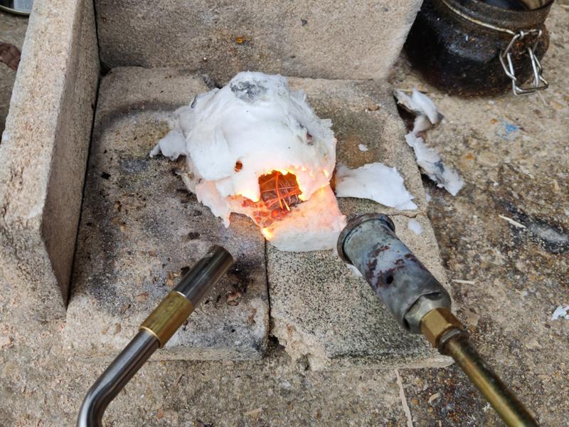
My usual approach to heat treatment is to do make a little tunnel from ceramic wool and use one or more blowtorches to heat the part. You can see an example of this in the following photo:
old_style_heat_treating_800.jpg


Judging the blade temperature is a combination of looking at the colour and testing it with a magnet. After testing, I usually stick it back in the flame for a bit to compensate for the temperature loss when testing it: it cools down quite quickly. All of that introduces quite a bit of variability.

Of course, I could just build a better frame (at bench height) and carry on using the blow torch, but if I'm going to do that, I might as well go the whole hog and try to build an electric oven.

I'm expecting the heat treatment oven to be a lot slower than the blowtorch approach. However, that extra time will be spent on the oven heating itself up rather than me squatting on the floor holding a blowtorch, so it should feel less like a chore.

My plan is to make it slightly unusual in that I'd like it to work in two orientations:

  1. Horizontally, so the door opens like a cabinet door: this would be used when heat treating as it keeps as much heat as possible in the oven when you open the door and also means you aren't looking down into something that's kicking heat upwards.
  2. Vertically, with the door at the top: this would be used when casting with a crucible lowered into the oven (putting the crucible on its side would be rather messy!) This is going to involve a few careful design considerations to make sure a crucible sits in a position where I can get some tongs around it.

I'd like it to be relatively small and it's important that it's not too heavy. The oven won't have a permanent home in the workshop (as I have no space) so I need to be able to move it for storage. Also, I'll definitely need to use it outside if I'm doing brass casting (to give any zinc fumes freedom to escape; I'll also be wearing a respirator if/when I do this).

My initial sketches suggest the internal volume will be approximately 154 mm × 154 mm × 200 mm, although the depth (last measurement) might reduce a bit. When casting, there will be some sort of stand for the crucible to sit on (effectively reducing the depth a bit) so that the top of the crucible is accessible for tongs.

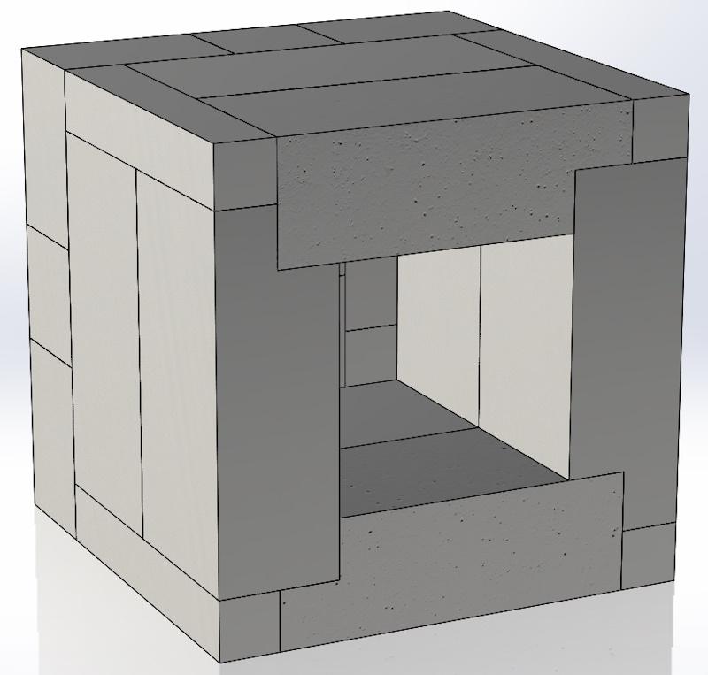
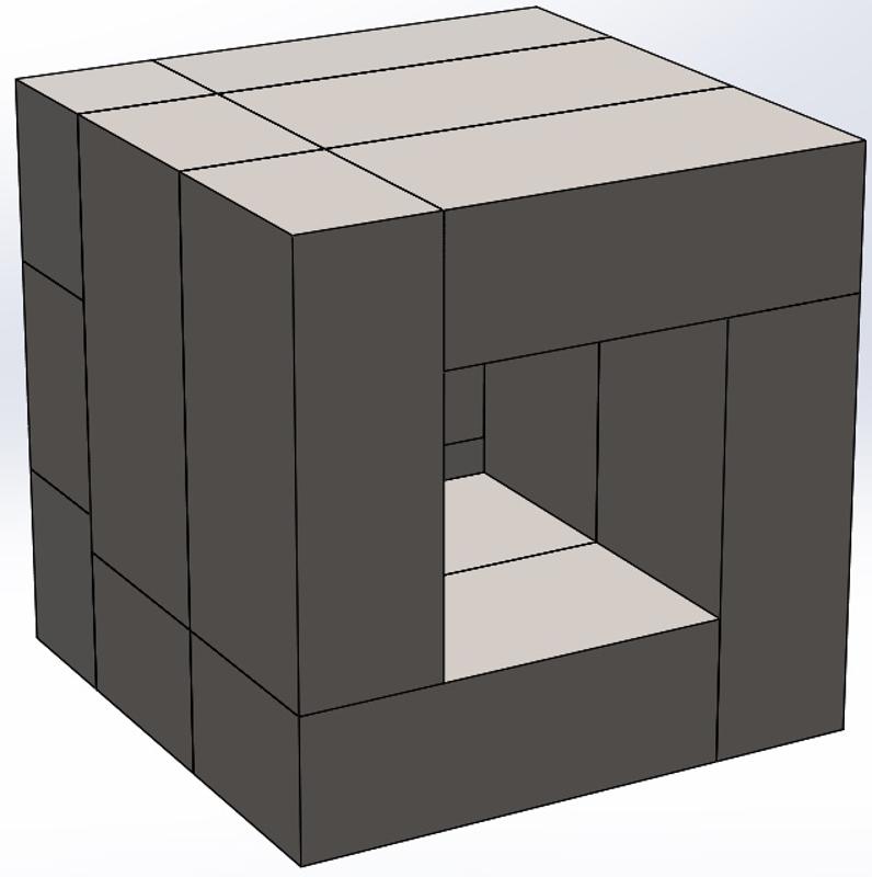
This CAD model image shows my current plan for the brick layout. The insulating fire bricks I'm expecting to use are 230 mm × 114 mm × 76 mm, and this layout gives 154 mm × 154 mm × 228 mm interior dimension. The door (not shown) will probably have a protrusion that goes into the opening a bit to improve the heat seal, hence the fact I'm expecting the internal volume to be slightly smaller.
body_brick_layout_800.jpg


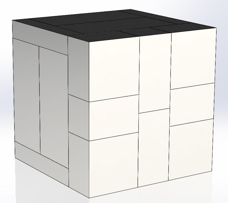
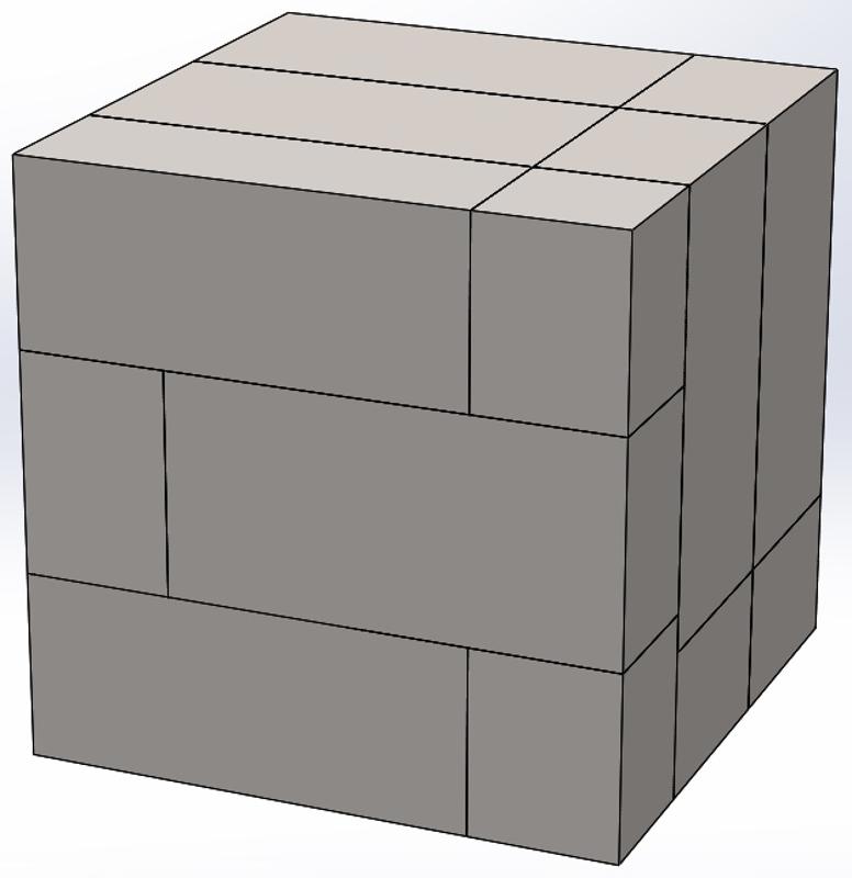
This CAD model image shows my current plan for the back face layout. The door will probably be laid out in much the same way. In theory, I can cut the three small bricks out of one full brick, but I'll buy extras in case it's necessary.
brick_layout_rear_and_door_800.jpg


That's about as far as I've got so far: there's still a lot of designing and planning to go. It'll be a fair while before I get started making anything so I've got plenty of time for planning.
 
It’s ages since I’ve seen one, if you can find a storage heater from the days of “economy seven “, the bricks in those would be idea.

Footnote: I’ve just looked at facebook marketplace and there’s loads of storage heater bricks there.
 
It’s ages since I’ve seen one, if you can find a storage heater from the days of “economy seven “, the bricks in those would be idea.
If I understand it correctly, they're the wrong sort of bricks: designed to hold heat rather than insulate heat. The insulating fire bricks help you heat the air inside, but not heat the oven too much. With storage heater bricks, it would take a heck of a lot more energy to heat the oven as you'd be heating those bricks up.

I know this because I've got some fire bricks that I bought a few years ago to make a crude heat treatment area & I bought the wrong sort :oops:
 
I just assumed ( wrongly it would seem).
What about the stuff that backs a traditional fireplace, is that ok?

I’m interested because I want to make a brazing hearth.
 
I just assumed ( wrongly it would seem).
What about the stuff that backs a traditional fireplace, is that ok?

I’m interested because I want to make a brazing hearth.
I've honestly no idea, but I'd guess it's okay. For less than £3 each, the proper bricks make sense to me for an oven, but I think that a brazing hearth just needs anything that will insulate.
 
Isn't there a difference between a heat treating oven and one that can be used as a furnace Al? I'm obviously not knowledgeable about this, but I spent quite a while with Will Catcheside a few years ago (knife maker in Herefordshire, if he's still there) learning to make knives and forge layered and folded steel. My recollection is that he used a repurposed scrapped domestic oven for heat treatments, which was readily controllable, and a much smaller white brick affair fed by propane I think, as a furnace. The later ran a great deal hotter.
 
Isn't there a difference between a heat treating oven and one that can be used as a furnace Al? I'm obviously not knowledgeable about this, but I spent quite a while with Will Catcheside a few years ago (knife maker in Herefordshire, if he's still there) learning to make knives and forge layered and folded steel. My recollection is that he used a repurposed scrapped domestic oven for heat treatments, which was readily controllable, and a much smaller white brick affair fed by propane I think, as a furnace. The later ran a great deal hotter.
You might be right: I'm not sure. I was working on the premise that these sorts of ovens can get above 1000°C and that's above the melting point of brass.

For steel forge work you probably want it a lot hotter: it cools down as you work it and would take a long time to heat the workpiece back up without the forge temperature being much hotter.

I guess I'll find out what's possible once I've made it. 🤔
 
Interesting, I shall as always follow with great interest.
Have you looked at pottery kilns? They get jolly hot! Might give you inspiration.

Yes: for a while I had a saved search on ebay in case one came up locally - I thought it would be a lot easier to just buy a kiln than make one. They tend to be a lot bigger than what I want (or have space for) and the smaller ones tend to be top-opening, which isn't great for heat treatment purposes. Also, making one sound interesting...
 
Following advice from the MIG welding forum, I'm going to revisit the brick layout to make sure that the top layer of bricks is fully supported rather than relying on a glue joint. In the meantime though, a bit of discussion of the control system might be of interest.

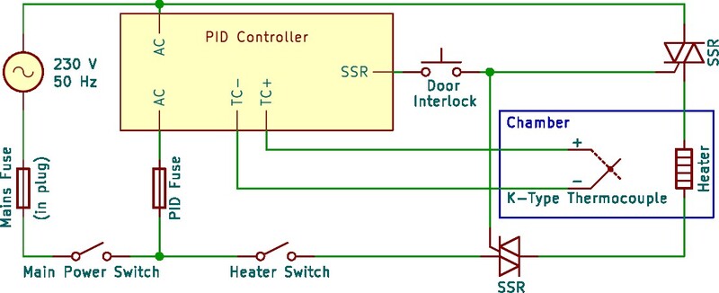
HeatTreatOvenSchematic_800.jpg


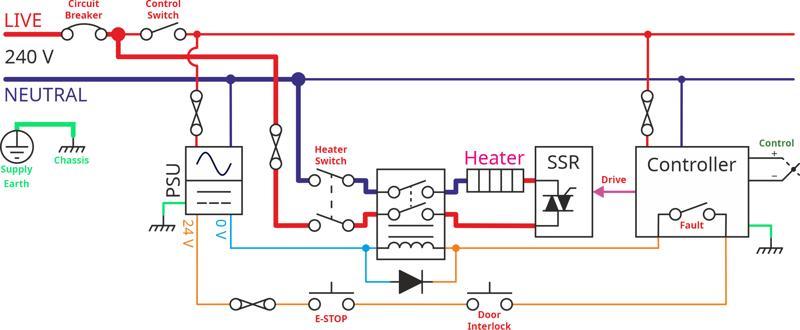
The diagram above shows a simple circuit diagram for the control system.

The oven will be controlled by a PID (proportional, integral, derivative) controller connected to the heating element via SSRs (solid-state relays, usually in the form of two back-to-back thyristors, often with an opto-coupler driving them, which I've omitted in the circuit diagram for clarity). In theory, one SSR would be sufficient; however, the typical failure mode of most SSRs is as a short-circuit and therefore it is safer to have two. The PID controller will read the temperature via a K-type thermocouple (K-type thermocouples have a maximum temperature of 1350°C) and control the current through the heating element in order to adjust the temperature to match a set-point.

Separate power and heating element switches are included so that the power to the PID controller can be enabled, the PID controller set up and then the heating element turned on when ready. An interlock is used to prevent the heating elements (which are connected to mains voltage) from being live when the door is open.

Choosing a PID controller is an important decision. As I see it, I've got four options:

  1. Pick a basic PID controller (circa £15–20) and accept that it can't do anything fancy like controlled temperature ramps.
  2. Pick a fancy PID controller (circa £90) that can do temperature ramps / soaks etc.
  3. Pick a mid-range PID controller (perhaps £30–40?) with an RS485/Modbus input. This would work much like the basic controller, but I could potentially add an external microcontroller to send commands over RS485 and implement temperature ramps / soaks myself if I ever felt the need.
  4. Implement the whole lot from scratch using a microcontroller and a home-designed circuit board.

I'm an electronics engineer by trade, so #4 is entirely plausible but it feels far too much like the day job and I doubt I could make that circuit board for less than the price of an off-the-shelf mid-range PID controller.

The third option (RS485 controller) is the most tempting of them all, but all the PID controllers I've found that have an RS485 input are either up at the price of the ramp/soak controllers or they can only handle temperatures up to 400°C.

That, unfortunately, leaves me with a choice of a simple, cheap controller or an expensive complicated one. At the moment I'm leaning towards the basic PID controller: if I find I need temperature ramps / soaks in the future, I can always replace the cheap one with a more expensive version at a later date.
 
When I built the controller for my guitar side bending machine, I bough my PID controller from this company.

Production Automation

I found them very helpful for a layman like me.

For the life of me, I cannot remember where I bought the SSR, but it was made in Taiwan and not the PRC. I seem to remember being advised to avoid the PRC SSRs.

And the control box has worked flawlessly ever since.

Edit. Just found the invoice. I bought the SSR from the same company.
 
When I built the controller for my guitar side bending machine, I bough my PID controller from this company.

Production Automation

I found them very helpful for a layman like me.

For the life of me, I cannot remember where I bought the SSR, but it was made in Taiwan and not the PRC. I seem to remember being advised to avoid the PRC SSRs.

And the control box has worked flawlessly ever since.

Edit. Just found the invoice. I bought the SSR from the same company.
Thanks Malc, that's useful. I'm a long way off buying stuff at the moment, but I'll have a look at that company when I get there.

Having said that, a very generous soul on the MIG welding forum posted this:

daleyd said:
Ooh watching this with interest! My day job is industrial controls, a lot of it for thermal processes.

I’d be happy to donate a few bits and bobs on the controls side from things I’ve “acquired” (ahem) over the years, pid controllers, contactors, SSR/thyristors etc if they are of any use to you.

If that works out then I may not need to spend too much time choosing controllers!
 
Very interesting thread. Some ideas might get copied if I decide to adopt knife making when I retire. Please educate me: for what application would you require heat ramping? Is it in practice more controlled cooling in say an annealing process, or are you going to be making things thick enough where you can't get the centre hot enough without ramping? Struggling to visualise the latter in a DIY set up. But this is a know nothing speaking.
 
Very interesting thread. Some ideas might get copied if I decide to adopt knife making when I retire. Please educate me: for what application would you require heat ramping? Is it in practice more controlled cooling in say an annealing process, or are you going to be making things thick enough where you can't get the centre hot enough without ramping? Struggling to visualise the latter in a DIY set up. But this is a know nothing speaking.

I think (but I really don't know) that it relates more to the type of material you're heat treating - some more exotic materials (as might be used in knife making) require a much more controlled application of heat, rather than just cook-it-and-dunk-it. Beyond that, I've no idea, but a couple of youtube videos I watched on the process suggested it was a nice-to-have feature.
 
Good luck with the project, wouldn’t be without mine for heat treating.

I bought another cheaply so I could have one for tempering without having to wait for my main one to cool- turned up and was the size of a fridge (was expecting more microwave size) which I need to find a home for as I don’t have that much luxury of space
 
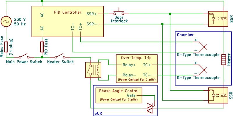
HeatTreatOvenSchematicMk2_800.jpg


Following some extremely helpful feedback from various people on the MIG welding forum, I've updated the circuit diagram. The main changes are:
  1. The addition of a second thermocouple, driving a temperature monitor (exactly what form this takes is still to be determined). The temperature monitor is there to cut the power to the heating element in the event of the temperature getting too high (i.e. if the SSRs fail). I've shown this as driving an electromechanical relay as it won't need to switch rapidly and is more likely to fail open-circuit, but it could also take the form of an SSR.
  2. The addition of a silicon-controlled rectifier (SCR), which could be used to reduce the power into the heating element if desired. I'm not sure whether I'll fit this straight away, but it's good to plan for its possible inclusion at a later date.
  3. I've changed the schematic symbol for the SSRs to make it clearer that there are two wires from the PID controller.
For now, I've left the second SSR in the circuit. In theory, the over-temperature relay makes the second SSR redundant (and reduces the risk of latent failures where one SSR has failed short and there's no way to tell, meaning I keep using the oven until the second one fails). However, it seems sensible to plan for it even if I don't eventually fit it.

The heating element will be made from "Kanthal A1" resistance heating wire, which is rated for use at temperatures up to 1400°C. I am currently planning on using 1.4 mm wire. Most oven builds I've seen use 1.2 mm or 1.3 mm wire. I couldn't find a source for 1.3 mm wire so the options were 1.2 mm or 1.4 mm. Thicker wire should mean better longevity (i.e. longer before I'll have to take the wire out and replace it). The disadvantages are that it'll take a bit more effort to wind it into a coil and that it's a bit more expensive. The resistance of the 1.4 mm wire is slightly lower than that of 1.2 mm wire (0.92 Ω/m vs 1.28 Ω/m), so this will need to be taken into account: with the 1.4 mm wire I need slightly more wire to get the same overall element resistance (which further adds to the cost over and above the fact that the thicker wire is more expensive).

ohm_watt.png


The overall resistance of the wire is chosen based on the target oven power or current. I'd like the oven to run off a standard 13 A wall plug, although I have a 32 A single-phase socket in the garage, so it wouldn't be the end of the world if I had to go for higher currents. If I aim for 10 A (which I believe is a sensible maximum safe continuous current for most standard UK sockets) then that means I want 25.3 Ω total resistance (the mains RMS voltage in the UK is 230 V ±10%, so the maximum RMS voltage is 253 V and Ohm's Law gives the resistance). That would be 27.5 metres of 1.4 mm wire (or 19.8 metres of 1.2 mm wire). The wire would be formed into a coil, reducing the physical length of the element while increasing its diameter. It's worth noting that this calculation only includes the current in the heating element and the 10 A target may have to be reduced a bit depending on the current consumption of the various bits of control gear (assuming they are all powered from the same plug as the element).

phase_control.webp


The updated circuit diagram above includes a phase-angle controlled silicon-controlled rectifier (SCR), which could be used to reduce the RMS voltage and thereby reduce the current for a given length of resistance wire. However, if possible, I'd like to design the system to be able to cope with full mains voltage across the element, even if I then decide to lower that voltage for actual use.

The power output of the oven at 10 A and nominal voltage (230 V) would be 2300 W. If I design for a 150 mm × 150 mm × 200 mm internal space, then that's 4.5 litres and hence the power would be 511 watts/litre. By comparison, the commercial Evenheat LB 18 and Paragon DB 18" heat treatment ovens work out as 188 watts/litre and 222 watts/litre respectively, so that suggests I could lower the current without having to worry too much about having enough power. Lowering the current means increasing the length of the wire (to increase the resistance) or reducing the RMS input voltage with the SCR. Those calculations are likely to change after I've revisited the brick layout (which may change the volume of the cavity).
 
The SCR: can you do anything to round the waveform off a bit? I fear you might lose a bit of local wireless coverage...
Ha! Yes, that's true. I think it would typically have a snubber of some sort across it to lessen the effect. I don't expect it would be EMC-compliant though. I wasn't planning on designing the SCR (if I even fit one), just buying an off-the-shelf module.
 
I haven't done much more thinking about the heat treatment oven over the last few months (life went a bit sideways as a result of my other half having a bad car accident), but the weather is starting to cool down and that makes the idea of this project a bit more appealing. I'd like to get this built over the winter so I need to make some more progress with the design.

The highest priority outstanding design question was the layout of bricks. I had some feedback on my first design that highlighted the unsupported bricks at the top of the cavity. Removing that issue while keeping roughly the same cavity size (to suit the intended use) and wall thickness (to keep the overall weight down) meant that I had to design it to have a lot more cut bricks. I've never handled insulating fire bricks before but from what I've read / watched it seems that they're relatively easy to cut so hopefully the large number of cut bricks won't cause too much of an issue.

This is the new layout of the body (which should weigh about 14 kg before all the metalwork and insulating wool is wrapped around it):

2024-10-23-01-body-brick-layout-mk2_800.jpg


The middle "slice" is a mirror of the front slice (i.e. the notch in the top brick is on the left rather than the right). In an ideal world, those four corner pieces will all come out of a single brick, but I plan to order quite a few spares in case of problems.

This is the layout of the back (which will also match the door):

2024-10-23-02-body-brick-back-mk2_800.jpg


If my maths is right (and there's minimal wastage) I think I can make the structure (including door) out of 19 bricks. At £2.76 each that works out as £52.44 for the bricks. In practice I'll order quite a few spares so it'll end up more expensive than that (but then I'll have allowance for breakage and/or non-optimal use of bricks). I'll also need to buy the ceramic fibre blanket to go around the outside, some fireproof rope for the door seal and some sort of mortar (perhaps this stuff or this stuff - I need to do more research here) to stick the bricks together. I think that'll be everything from Vitcas but there are lots and lots of other bits needed from other suppliers. I'll probably order the Vitcas stuff fairly soon as it's often helpful when designing things to have some of the materials to hand.

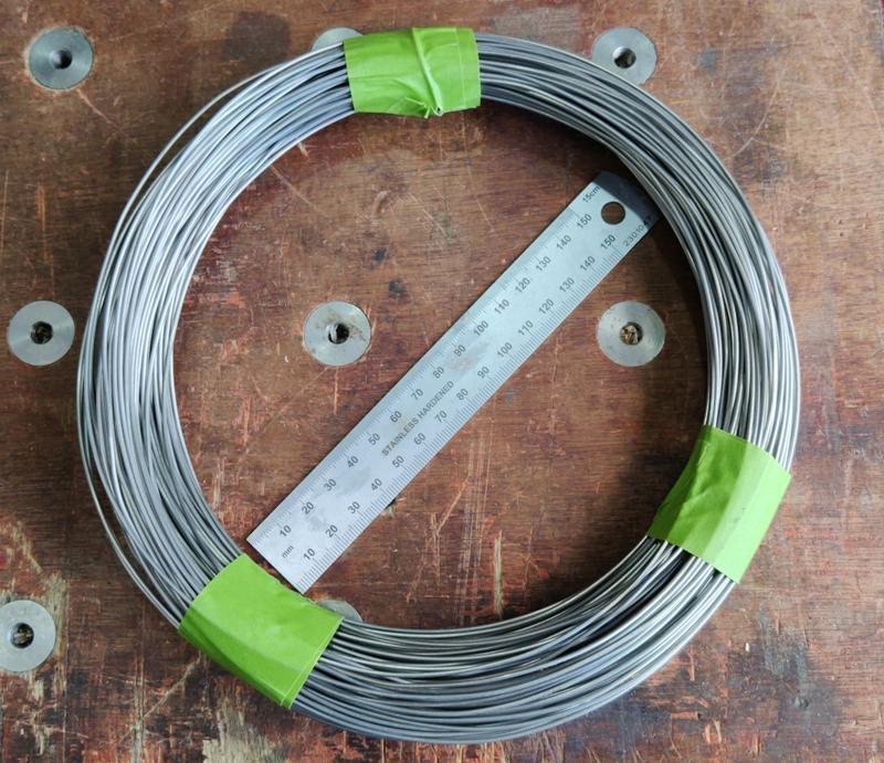
Speaking of ordering stuff, I have now bought the first part of the oven: the Kanthal A1 heating wire. As described in the previous post, I went for 1.4 mm diameter wire. The cavity in the new design is the same size as in the old so the calculations in the previous post should still be valid. Those calculations suggested 27.5 metres of wire. The disadvantage of using the thick wire and hence having a long length is that it might end up being quite a lot of coiled element to fit in the relatively small cavity I've designed - something I'm putting off thinking about for now! I had the choice of 25 metres or 50 metres so erred on the side of caution and bought 50 metres. This is what it looks like as delivered:

2024-10-23-03-kanthal-wire_800.jpg


I need to form that into a heating element coil for use, but I'll leave that for a while (as it takes up less storage space in a loop than it will when formed into a coil). I can't put it off too long as it could affect the brick design (if there's simply too much to position in the cavity) or force me to use something to reduce the current (e.g. an SCR or a step-down transformer).

I've had a very kind offer of a very fancy PID controller and some other control gear from a fellow member of the MIG welding forum, so I'm in the process of working out exactly what the control schematic is likely to look like (in a bit more detail than previously described) and also looking at the capabilities of that controller to see if there's anything else that would be interesting to include. The controller manual is 465 pages long so there's quite a bit of reading to do! The controller has multiple inputs and outputs (to allow monitoring various things as well as the SSR control). I've updated the schematic to try to take advantage of some of those features (click for a bigger view):

2024-10-23-04-latest-schematic.jpg


The idea of the new schematic is that the controller can monitor temperature at two different parts of the oven. It only has one method of controlling the temperature of the oven (via the heater), so it'll probably use one of the thermocouples for temperature control and the other for logging and tracking. I'd wondered about using the second thermocouple input as a safety shut-off, but I think I prefer the idea of having a completely independent (and much simpler) over-temperature shut-down system so I've left that as a third thermocouple.

As the controller has inputs that can be used as current inputs (I'm guessing they're 4–20 mA but I haven't read the manual enough to know) I should also be able to use a third input to monitor temperature (again just for interest) and a fourth one for a potentiometer input (i.e. a control dial). Combined with the various digital inputs and outputs, I think this should allow me to have four different operating modes (with different programs), such as:

  1. Typical heat cycle for hardening (i.e. heat it up and hold the temperature).
  2. Typical heat cycle for tempering, possibly with potentiometer based tweaking (i.e. heat it up to a lower temperature and hold it there for a set time, then cool).
  3. Typical heat cycle for melting brass (similar to #1 but a different temperature).
  4. Heat up to a temperature set by the control dial.

That might be stretching my ability to program the controller but if it can do all of that (and I can figure out how to make it happen) then it could make for quite an easy-to-use but versatile bit of equipment. Of course there will be nothing stopping me reprogramming the controller to do something completely different if needed.

The disadvantage of all that is the number of parts to design / buy or otherwise get hold of (and then do something with) is getting longer and longer, so I reserve the right to dampen my ambitions a bit!
 
Time is running out! Okay, that's a bit of an exaggeration as there isn't really a dead-line for this project. However, I've got two weeks off work over the Christmas break. Most of one of those will be occupied with family stuff but I'd like to use the second week to start building this oven. I doubt I'll finish it in that time, but I'd like to make some solid progress if possible.

Given that most suppliers will be closed over the Christmas break, that means I need to start ordering stuff very soon if I'm going to get it before the break.

Following some conversations on the MIG-welding forum, I now feel like I'm getting close to a shopping list of stuff I need to acquire:

Heat Zone Stuff:

  • Insulating Fire Bricks, Grade 23 (plus spares!)
  • Fire rope (for the door seal)
  • Kanthal Wire (I already have this)
  • K-Type Thermocouples (3)

Note: I'm not going to buy high temperature mortar or ceramic wool as both are apparently unnecessary.

Control Cabinet Stuff (some of this is probably overkill, but overkill can be fun!):

  • PID Controller
  • Thyristor / controller of some sort (I don't think I'll do anything very fancy with this, just set a target current).
  • Two SSRs (and heatsinks if they need them)
  • Mains voltage relay (for over-temperature safety trip)
  • Something to measure temperature from a thermocouple and trip the relay (I'm not sure what options there are for this at the moment, but hopefully something fairly simple and reliable)
  • A current transformer (not strictly necessary as current monitoring will mostly be for interest)
  • Some DIN rail
  • Cable glands and such-like
  • Fuses & fuse holders
  • Switches (including a couple of mains-rated ones), potentiometers, LEDs (I've probably already got some of this)

Other Chamber Stuff:

  • Angle iron for the frame (I've got loads of box section, so I had pondered cutting it in half diagonally; that would result in a lighter frame as it's 2 mm wall rather than the 3 mm typical of angle iron, but it's probably a lot more faff than I can be bothered with)
  • "Bullet" hinges for the door
  • Door interlock switch(es)
  • Ceramic terminal blocks for the electrical connections to the chamber
  • Thermocouple extension cables?
  • High temperature rated power & signal wire

I think that's everything at the moment. I'll have to make a control cabinet but I've got some sheet steel to use for fabricating that. I'm sure there are other minor bits and bobs I've forgotten but hopefully that lot will get me most of the way there.

Anything you can think of that I've forgotten?

I'm working on the premise that the control cabinet will be relatively big, but I'm planning to make it a separate piece to the main chamber rather than having the cabinet permanently fixed to the side of the chamber. There are two reasons for that:

  1. It will make it much easier to re-use the control cabinet with a different chamber if I decide I want a different cavity size or something like that.
  2. It will make it easier to transport to/from storage as I can carry the chamber in one trip and the cabinet in a second.

The main disadvantage of that approach (that I can think of) is that I'll have to make sure that all the connections (thermocouples and heater) to the chamber are relatively easy to disconnect/reconnect and extremely easy to identify (so the right connection goes back to the right place).
 
So by the end of the second week of your time off work you will have the oven ready and tested? I understand much of what you are creating except for the electronics. No complaint, it's just me!
 
So by the end of the second week of your time off work you will have the oven ready and tested?
I suspect it'll take longer than that, but I'm hoping to make at least a decent amount of progress. I don't think I'll manage anything in the first week & I don't have any feel for how long the work will take.
 
2024-12-14-01-accumulating-stuff_800.jpg


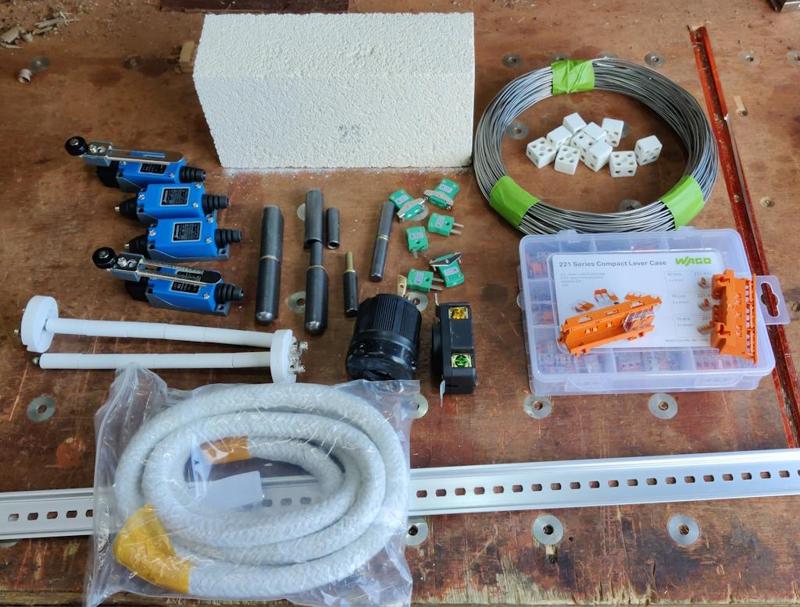
I've been gradually accumulating some of the stuff that will go into the heat treatment oven build. Most of this is shown above, although there are plenty of other things not shown, either because I've already got them buried in a drawer somewhere or because they're still to come (most of the remaining stuff is the control gear, which an exceptionally generous member of the MIG welding forum has offered to donate).

In the picture above, you can see:

  • An insulating fire brick
  • A selection of (blue) interlock switches for the door
  • Some bullet hinges
  • Some (white) thermocouples and (green) thermocouple connectors
  • The heating element wire
  • Some ceramic terminal blocks for connecting to the heating element
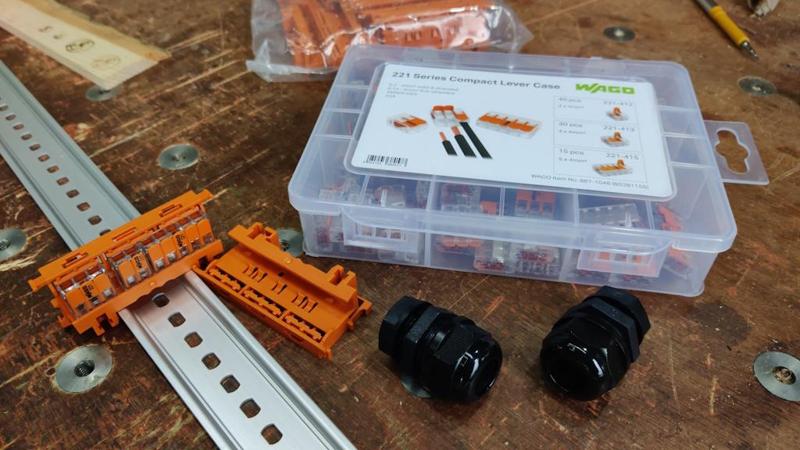
  • Some Wago connectors and mounting blocks (orange)
  • Some fire rope to seal the door
  • Some DIN rail to mount control stuff on
  • A heavy duty (black) connector pair to connect the heating element to the control cabinet

The last one is there so that I can have a separate control cabinet to the oven (rather than trying to integrate it into the unit). I explained the reasons for that in the last post, so I won't echo them again here.

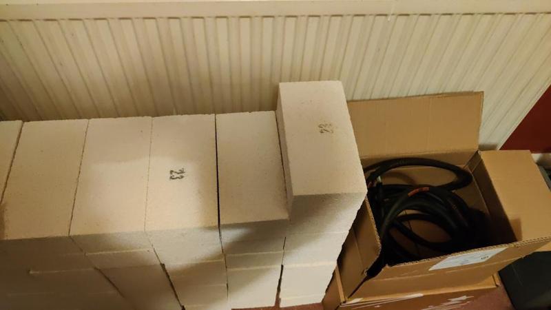
I only showed one insulating fire brick in the photo, but there's actually a rather large stack of them piled up in the dining room, along with a box with some thick 3-core wire:

2024-12-14-02-pile-of-bricks_800.jpg


I bought **way** more bricks than I'll need for the build. The delivery cost ended up being quite high and I really didn't want to pay it twice. I also like the idea of being able to make more than one chamber, so having excess bricks should make that possible. The extras also give me a bit of resilience to mistakes!

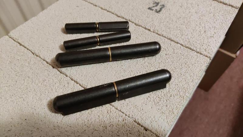
In the top photo, there were two different sizes of (weld-on) bullet hinges. You can see them a bit clearer in this photo:

2024-12-14-03-two-sizes-of-bullet-hinge_800.jpg


I originally bought the smaller ones, having read the dimensions on a website and thought they sounded about right. When they arrived they looked a bit weedy. I could have returned them but I thought they'd be useful for the control cabinet (which I'm planning to make from scratch rather than doing the sensible thing and buying a project box). The bigger bullet hinges will be used for the chamber.

The little orange plastic pieces that are (in the top photo) sitting on top of the Wago connector set are used to allow mounting of Wago connectors on the DIN rail:

2024-12-14-04-wago_800.jpg


I suspect that the wiring of the control cabinet could be quite complex, so this will hopefully help with keeping things under control.

In the next post, I'll try to cover the control cabinet system implementation in a bit more detail. It has got a lot more complicated than originally envisaged as a result of the fancy control gear I've been offered, but more on that in due course...
 
Looks like a good project to watch.

The bricks - if I recall correctly they can be sawn using a metal hacksaw.
The smaller sections are placed in a bottle of paraffin and left to soak.
They are then extracted for use as firelighters.
Once cooled down, place into bottle, repeat, repeat, repeat, only cost is some paraffin.
 
Looks like a good project to watch.

Thanks

The bricks - if I recall correctly they can be sawn using a metal hacksaw.

From what I've heard, they can be sawn using almost anything. A tired old woodwork hand saw seems to be quite a popular choice.

The smaller sections are placed in a bottle of paraffin and left to soak.
They are then extracted for use as firelighters.
Once cooled down, place into bottle, repeat, repeat, repeat, only cost is some paraffin.
That's one I've never heard before. I can see how it might work though given they withstand such high temperatures. I don't really use firelighters though: it's rare that I don't have enough plane shavings around to do the job.
 
There are projects now and then which I watch without commenting on, for the simple fact that I have nothing useful or interesting to say on the matter. This is one of those. I hope it goes well for you Al.
 
There are projects now and then which I watch without commenting on, for the simple fact that I have nothing useful or interesting to say on the matter. This is one of those. I hope it goes well for you Al.
Thanks Mike. I wasn't expecting a great deal of input from this forum (although, of course, any is welcome). I'm mainly posting it here just in case anyone finds it interesting.
 
If anyone is interested in colouring metal, this book is stunning. I was lucky, I picked it up for £15.
 
Back in my second post in this thread, I talked a bit about the four options I had for a PID controller for the oven build. What I said then was this:

Choosing a PID controller is an important decision. As I see it, I've got four options:

1. Pick a basic PID controller (circa £15–20) and accept that it can't do anything fancy like controlled temperature ramps.
2. Pick a fancy PID controller (circa £90) that can do temperature ramps / soaks etc.
3. Pick a mid-range PID controller (perhaps £30–40?) with an RS485/Modbus input. This would work much like the basic controller, but I could potentially add an external microcontroller to send commands over RS485 and implement temperature ramps / soaks myself if I ever felt the need.
4. Implement the whole lot from scratch using a microcontroller and a home-designed circuit board.

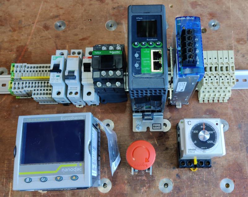
It turns out there's a fourth option that came out of the blue. An extremely generous member of the MIG welding forum read my posts about the heat treatment oven and offered to send me (free of charge) a selection of very fancy control gear for me to use in the oven. This is what came in the package he sent:

control_gear_from_dale_800.jpg


I'll talk through what all of that stuff is and does shortly, but for the impatient, there's a very, very fancy PID controller, a very fancy thyristor current controller, a contactor, a power supply, an temperature monitor, some circuit breakers, an emergency stop button and various connectors / fuse holders.

I have been completely blown away by the generosity shown (from someone I've never met).

The negative thing about this gift package (and believe me when I say this isn't a complaint!) is that my aim to document this heat treatment oven build in a way that will hopefully be helpful to others attempting the same thing will be slightly hindered in that most people won't have access to such fancy control gear. As such, I'm also going to try to write-up how I would have done it without all the posh kit!

Anyway, back to the posh-kit version of the build...

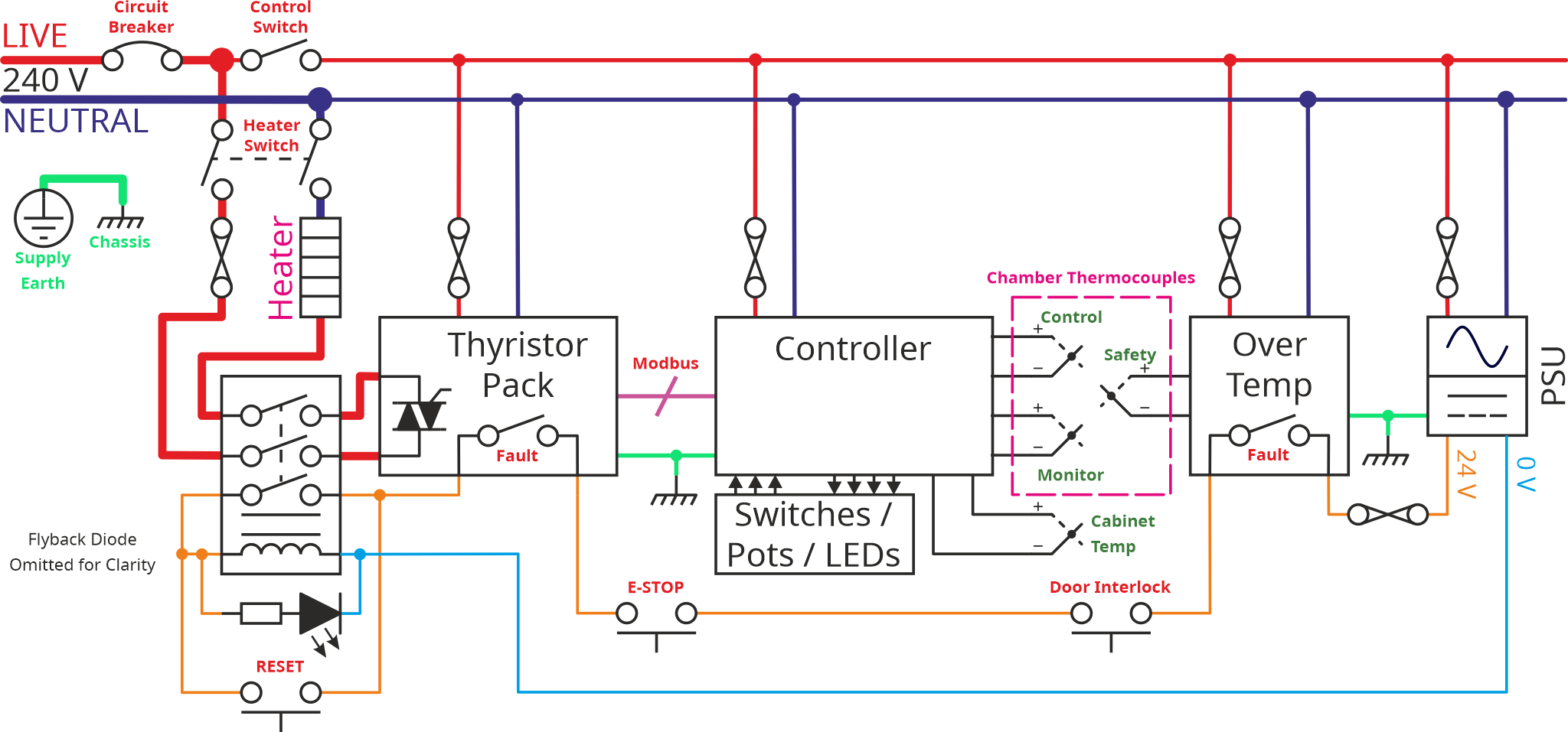
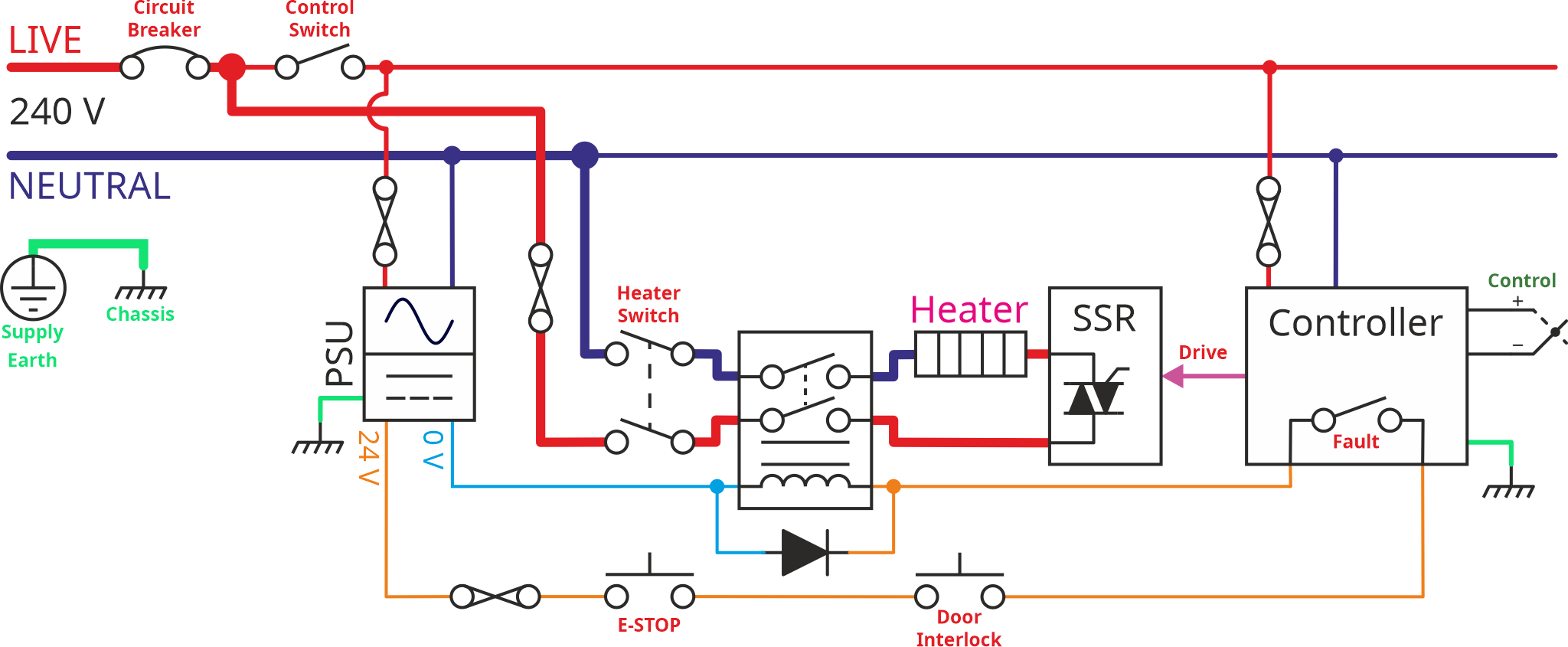
With the selection of control gear I now have available to me, I can revisit the schematic of the control cabinet (I also had a lot of help from my generous benefactor with working out the best way to do this). This is the new schematic:

ControlCabinetSchematic-AlternativeLayout_2024-12-19.png


While it's a bit prettier than the previous drawings I've done, I'm conscious that it's also a lot more complicated so I'm going to try to explain it bit-by-bit in the hope that it helps.

Let's look at the power circuit first, by deleting everything else from the schematic and just focusing on that bit:

ControlCabinetSubCircuit-PowerCircuit-2024-12-19_800.jpg


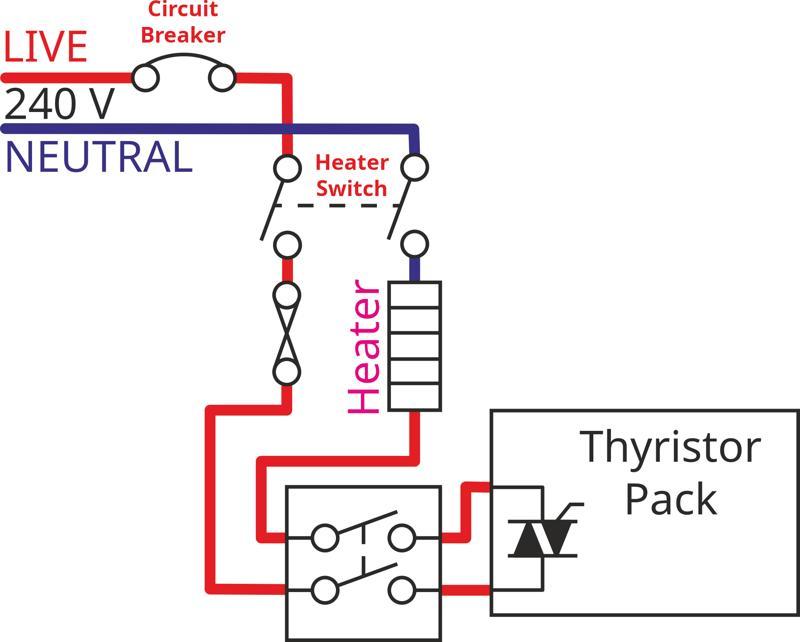
It's still a little complicated I think due to the layout being better suited to a complex diagram than this simplified version, so let's lay it out in a simpler way. Hopefully by comparing the previous image with the next one, you'll be able to see that they represent the same circuit.

ControlCabinetSubCircuit-PowerCircuitRelaidOut-2024-12-19.png


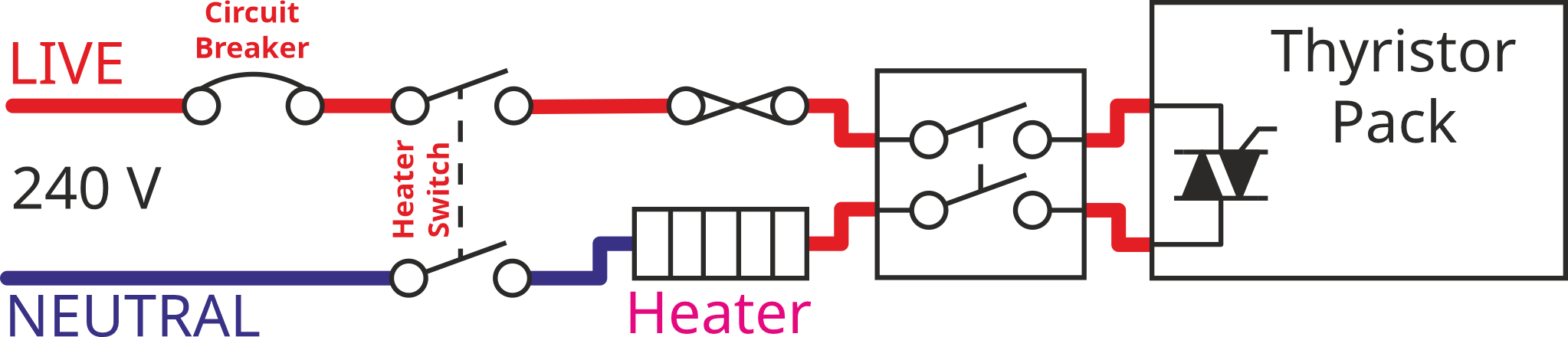
The power from the mains supply first goes through a circuit breaker. That will protect the system from massive overcurrents. A little bit later in the circuit (after the heater switch) I've also added a fuse (the thing that looks like two circles joined with a cross - that's a slightly old-fashioned symbol for a fuse, but I think it's a bit prettier than the modern one that looks like a resistor with a line through it). The fuse is arguably a bit pointless with the circuit breaker there to protect things. However, I thought I'd include the fuse as an extra layer of protection and also as dedicated protection for the heating element (the circuit breaker also provides power to the control electronics).

As well as the overcurrent protection devices (circuit breaker and fuse) there are couple of linked switches in the diagram. One of these is a simple toggle switch, the other is a contactor (basically the same thing as a relay, just a bit bigger). I haven't shown the contactor coil in this diagram but you can see it if you look at the first schematic in this post.

The switch is arguably unnecessary with the contactor there; however, I quite like the idea of being able to hit a switch and know for certain that the mains connection to the heater has been removed.

The contactor is there to cut the power to the heater in the event of any fault in the system. I'll talk about that a bit more in the next post when we come onto the safety circuit. The one thing to note (from the main schematic) is that the contactor isn't a switch that the user would ever touch, the switches are closed as a result of current flowing through the contactor's coil.

Finally, there's the thyristor pack. Unlike the solid state relay (SSR) used in the simpler version of the circuit (and the version shown in the schematics in earlier posts), the thyristor pack can control the level of current (rather than just relying on the mains voltage, the heater resistance and Ohm's Law) as well as turning it on and off. This means that the heater can be run at a lower power if desired/required.

That's it for the power circuit. It looks complicated but there aren't that many components in there. In the next post, I'll talk about the safety circuit in detail and then revisit some of the other features of the design. I'll then discuss what a simpler (cheaper) version of this circuit would look like.
 
In the last post, I introduced this schematic:

ControlCabinetSchematic-AlternativeLayout_2024-12-19.png


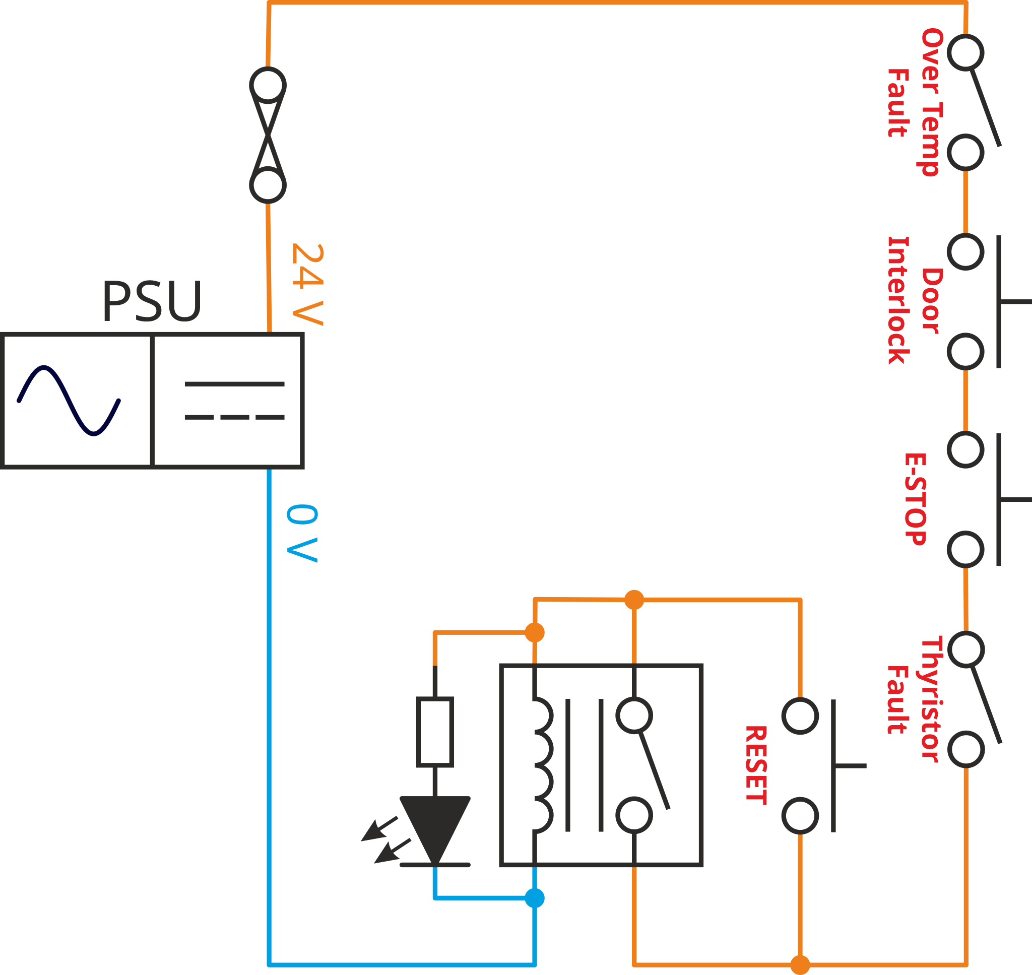
I then went on to discuss the power circuit in a bit more detail. This time I'm going to talk about the low voltage safety circuit used in the new design. If I redraw the safety circuit in an alternative layout (showing only one of the switches in the contactor), you can hopefully see that it's really quite simple:

ControlCabinetSubCircuit-SafetyCircuit-2024-12-19.png


The box with the switch, the vertical lines and the inductor (four semicircles in a line) is a contactor. Remember that the term "contactor" basically means "big relay". A relay is an electromechanical component with a coil and one or more switches. The switches are opened or closed through the application of current through the coil. The current in the coil causes it to act as an electromagnet, pulling the moving part of the switch one way or the other in order to open or close a switch. In this case, the switches are all normally-open, i.e. when current isn't flowing in the coil, the switches are open and when (sufficient) current flows in the coil, they close (and allow current to flow through the relay's switches).

The power supply produces 24 V (from a mains input); the output of the power supply is fused in case of problems. There are then a series of switches, each of which will open in the event of a problem. For now, ignore the switch marked RESET and the resistor/diode to the left of the contactor.

With those ignored components gone, the current from the power supply goes through four switches, then through one of the contacts (switches) inside the contactor, then through the coil of the contactor, then back to to the power supply.

If any of the switches open, the contactor will deenergise (as there will no longer be current flowing in the coil) and the contactor's switches will all open. Since two of the switches (not shown in the safety circuit diagram) are in the heater power circuit, the heater will be rendered safe whenever the contactor deenergises.

The reset button is there to resolve a simple problem with the circuit layout. While it's great (i.e. safe) that the contactor will be deenergised when power is initially provided to the system (as one of the contactor switches in the circuit with the coil), to turn the system on, you need to be able to bypass the switch inside the contactor. The reset push button does that: with power applied and all the other safety switches closed, press the reset button and current will flow through the coil causing the contactor to energise. The reset button can then be released (as the contactor switch will be closed, maintaining the connection).

The last part of the circuit is a resistor and LED. In practice, this will be a single component (a 24 V lamp), but I prefer to draw it showing what's happening inside that lamp. When the various safety interlocks are closed, the lamp will be on; if any of them trip, the lamp will turn off. That'll help make it obvious whether power is available to the heater.

In the next post, I'll talk a bit about the simpler version and then I'll come back to this schematic and talk about some of the complexities of all the fancy new control gear I now have.
 
The last couple of posts have discussed this rather complicated control cabinet circuit:

ControlCabinetSchematic-AlternativeLayout_2024-12-19.png


This time, I'm going to talk about a much simpler (and much cheaper to build) version of the circuit:

SimpleControlCabinetSchematic_2024-12-19.png


It's worth noting that there are definitely cheaper and simpler ways of making it than this. I went with this layout for the purposes of the explanation as I think it covers a lot of the bases while also being affordable. Anyone implementing this themselves can make their own decisions on whether they want to include everything.

If you compare the two circuits, you'll see there are a lot of similarities. The biggest differences are that the controller is much simpler, there's no over temperature monitor (more on this later) and there's a solid state relay (SSR) instead of the thyristor pack. You'll also notice a different sort of diode near the contactor; again I'll discuss this below.

To give an idea of the cost of this control system, there are four major components involved:
  • Power supply
  • Controller
  • SSR
  • Contactor

A very basic PID controller and SSR can be bought as a package on amazon for £16. A DIN-rail mounted 24 V power supply with sufficient power output to drive a contactor coil can be found for a bit under £20. A three-switch contactor with a 24 V coil can be acquired for about £11 (contactors with mains voltage coils are also available, which would save the cost of the power supply, but I'd rather have the safety circuit as a low- voltage one).

Thus, all the major components can be bought for about £50.

Let's look at that schematic again:

SimpleControlCabinetSchematic_2024-12-19_800.jpg


If you compare this with the more complicated version at the top of this post, you'll hopefully see that the power circuit is essentially the same: circuit breaker, fuse, switch, contactor, heater, control device (this time an SSR rather than a current-controlling thyristor pack). I've moved the fuse to the other side of the switch, but the fuse location isn't that critical and (in both diagrams) I picked the location mainly based on what looked neat on the diagram!

The big difference comes with the controller. I'll talk more about the control strategy in the more complex circuit later, but let's look at the simple one first. In this system, the controller monitors the temperature from a single thermocouple and uses that output to decide whether to turn the SSR on or off. It may do more fancy things like turn it on and off quickly in order to get an **average** current that's a bit less than the maximum, but let's keep it simple and imagine it just turns it on and off according to temperature.

That's really all there is to this system. The controller has a fault output, so I've wired that up to the contactor as before, along with the emergency stop button and the door interlock (which ensures that the heater isn't live when the door is open). I'm not sure I'd entirely trust the controller's fault output and I'd prefer to have an independent temperature monitor, but I was going for a fairly cheap system with at least a bit of protection built in.

The last thing that's worth noting in this simple schematic is the diode I've drawn across the contactor/relay coil. It would work without that (and some relays even include the diode inside the package, although I think that's quite rare). However, an inductor (which is what the coil of a relay is, although it's a little more complicated than that) resists the **change** of current flowing through it. For the mathematically minded, the voltage-current equation of an inductor is:

294a2c52ae2d841d8cd161e00fd64ce7.png

In that equation L is the inductance and is a constant. What that means is that the voltage (V) is proportional to the **rate of change** of current. If the current changes from 1 A to 0 A in 1 second and the inductance is (implausibly) 1 Henry, the voltage across the inductor will be 1 V. If the current changes from 1 A to 0 A in half a second, the voltage will be 2 V. If you open one of those switches, the current effectively changes from (say) 1 A to 0 A in 0 seconds, resulting in a theoretically infinite voltage. That high voltage causes an arc across the switch contacts. Do that lots of times over and the switch contacts will become blackened and corroded and won't work any more.

Where the coil is driven with a DC supply (as it is here), putting a diode (known variously as a "flyback", "freewheeling" or "catch" diode) across the relay coil gives the current in the inductor an alternative path (rather than trying to arc across the switch contacts) and the current decays gracefully without damaging anything.

I'm planning to put a freewheeling diode in the more control cabinet, but I omitted it from the schematic diagram as it felt like it was getting cluttered enough without the diode!

That's it for this post. In the next post I'll probably talk about the fancy new controller and the (much simpler) over-temperature device. I'll also talk about why I've included so many thermocouples and what my ideas are for the block marked "Switches / Pots / LEDs".
 
You are probably aware of this but you need special cable called "compensating cable" to connect thermocouples. If you use plain copper you risk introducing significant measurement errors.

I'll explain why if anyone is interested.
 
Back
Top