• Hi all and welcome to TheWoodHaven2 brought into the 21st Century, kicking and screaming! We all have Alasdair to thank for the vast bulk of the heavy lifting to get us here, no more so than me because he's taken away a huge burden of responsibility from my shoulders and brought us to this new shiny home, with all your previous content (hopefully) still intact! Please peruse and feed back. There is still plenty to do, like changing the colour scheme, adding the banner graphic, tweaking the odd setting here and there so I have added a new thread in the 'Technical Issues, Bugs and Feature Requests' forum for you to add any issues you find, any missing settings or just anything you'd like to see added/removed from the feature set that Xenforo offers. We will get to everything over the coming weeks so please be patient, but add anything at all to the thread I mention above and we promise to get to them over the next few days/weeks/months. In the meantime, please enjoy!

Holiday Toolchest

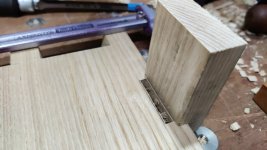
One thing to add is that if you don’t have a true (flat and square) end to your board, you can’t use it as a reference to mark the shoulder line (ie you can’t use a marking gauge off the end grain to mark the shoulder line). Instead, you’ll have to mark it using a knife and square off your reference edge.

None of that is an issue of course, but is something to be aware of.
 
Thanks all...

Mike G":8waaie72 said:
Saw sort-of accurately by hand, as the planing post-dovetailing will sort it all out. You could try the knife-and chisel-groove technique for accurate sawing if you wanted.

I'm definitely leaning that way at the moment (using the knife and chisel groove thing sounds like a good idea to help me along). I guess I can do one end of each of two of the boards and prepare the first dovetail and then decide whether it was a good idea or not!

AndyT":8waaie72 said:
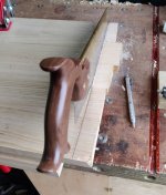
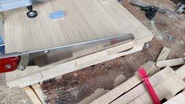
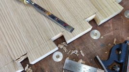
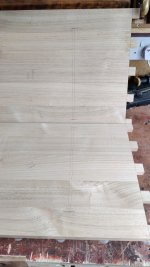
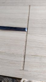
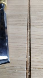
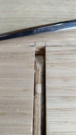
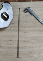
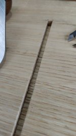
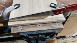
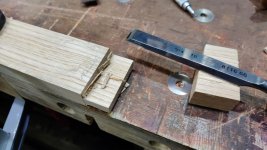
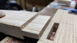
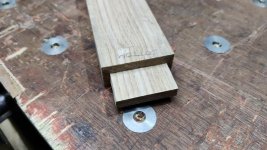
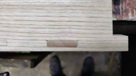
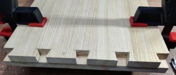
Al, there are several ways to make that cut by hand. Here's a photo of the top of a chest of drawers I made back in 2015. I had squared a knife line across, then deepened it with a chisel, and used a 14" tenon saw to cut all the way across in one line. Advantages: if you get it right you get a really straight cut. It's up on the bench where you can see what you are doing. Difficulties - the saw can jump out of the groove; if your saw is too fine the teeth will clog - so make sure you take the saw well forward to clear the sawdust. Also, you need enough depth of sawplate below the handle to clear the thickness of the wood - probably not a problem in your case.

I'd also use this sort of cut if I was making long housings.

View attachment 3

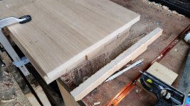
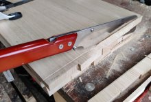
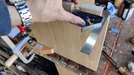
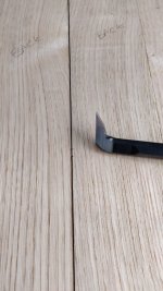
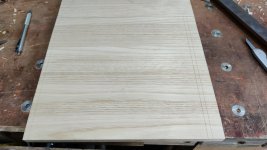
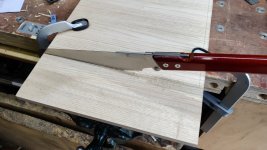
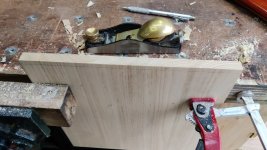
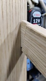
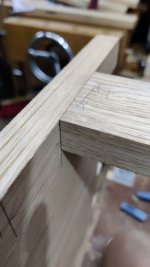
More conventionally, you'd just use a handsaw. I didn't join these two oak boards together, but they were a similar sort of width. I just used a Workmate as the only available way to get my body above the work and saw downwards.

View attachment 2

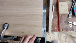
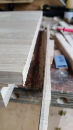
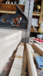
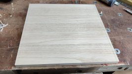
I was quite pleased with this cut across the end, which left a small enough sliver for me to plane away

View attachment 1

I guess you will also have the option of a Japanese saw for that cut. ;)

Thank you for sharing those photos: they're really useful (I do have a 14 tpi cross-cut western tenon saw, so I could even try using western sawing methods). I might see if I can dig out an offcut of 18 mm plywood and do some practice cuts. The side panels are currently long enough to get 330 mm tool chest height and the design is for 300 mm, so if I mess it up the first time (on the side panels), I'll still have a bit of wiggle room! There's less room for manoeuvre on the top and bottom piece (although I could always modify the design to suit the panels that are left).

spb":8waaie72 said:
Yes, if they're being dovetailed then the ends don't need to be perfect as long as there are no 'low' spots. The critical dimension is between the marked shoulder lines for the joinery; as long as there's at least the other board's thickness beyond the line at all points then you can plane off any excess material after glue-up.

Obviously the exception to this is if you don't have a big enough square to mark those shoulders from an edge and have to use a marking gauge from the end grain. In that case you do need the ends to be perfect.

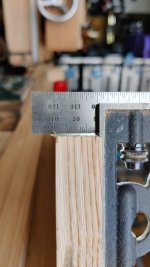
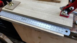
I've got a big framing square somewhere (although I'll have to check it's still square as it's been a while since I last used it). However, I usually find that using a 300 mm combination square and a 1 mm thick, 600 mm long ruler slid up to it works quite well for long squared lines.

Andyp":8waaie72 said:
I would KISS it. If a track saw is quick, very easy and very accurate why make hard work and risk undoing all the good work so far?

Well, yes, it would be easier! However I am trying to do more in the way of hand tool work to build up my skills (which are seriously lacking when it comes to sawing accuracy, hence the dilemma here).

In some ways it wouldn't be quite as quick as I'd implied to use the track saw anyway. If you remember that photo I posted a few weeks ago of the newly acquired chestnut...

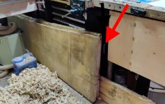
cabinet_handle.jpg

... the big red arrow is pointing at the handle of the door to the cabinet in which the track saw lives, so it's not exactly accessible at the moment!

At least that gives me a bit of encouragement to do it by hand :lol:

NickM":8waaie72 said:
One thing to add is that if you don’t have a true (flat and square) end to your board, you can’t use it as a reference to mark the shoulder line (ie you can’t use a marking gauge off the end grain to mark the shoulder line). Instead, you’ll have to mark it using a knife and square off your reference edge.

None of that is an issue of course, but is something to be aware of.

That's an interesting point that I hadn't considered, so thank you for raising that. It also means that I can't use my 3D printed sawing guides to help with my (lack of) sawing accuracy when cutting the dovetails (as they reference off the end surface), which makes everything even more scary :? :) :eusa-shifty: :D
 
Dr.Al":3l23kley said:
That's an interesting point that I hadn't considered, so thank you for raising that. It also means that I can't use my 3D printed sawing guides to help with my (lack of) sawing accuracy when cutting the dovetails (as they reference off the end surface), which makes everything even more scary :? :) :eusa-shifty: :D

Remember though that the angle of those cuts only needs to be visually correct; since you'll be referencing from the actual cut to mark the pins, the tail cuts don't need to be joinery-accurate.
 
spb":3w4tgm2b said:
Dr.Al":3w4tgm2b said:
That's an interesting point that I hadn't considered, so thank you for raising that. It also means that I can't use my 3D printed sawing guides to help with my (lack of) sawing accuracy when cutting the dovetails (as they reference off the end surface), which makes everything even more scary :? :) :eusa-shifty: :D

Remember though that the angle of those cuts only needs to be visually correct; since you'll be referencing from the actual cut to mark the pins, the tail cuts don't need to be joinery-accurate.

True if I rely on my accurate (ahem) sawing. If I use the 3D printed guides (with a square-ended board), the guides help with the pin cuts as well as the tail cuts - I still mark the pins from the tails (so I know where to hold the guide), but the guide keeps the saw at the right angle for the (guided-cut) tail and also square to the end. It makes it very quick to cut accurate dovetails and takes all the sawing accuracy out of the process. Yes, I know it's a crutch, but it works...
 
After a bit of pondering, I decided to go with a hybrid approach :)

I'm trying to make the most out of the wood that I've got and hence don't want to cut much off the end beyond what's required to square the boards up and get them to equal lengths. As a result, there are different amounts to come off different bits of the boards:

different_amounts_to_cut_off.jpg

One some sections of some of the boards, the amount being cut off is less than a millimetre; in other areas it's as much as 50 mm.

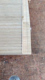
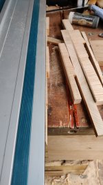
I didn't fancy trying to guide a handsaw along the cut when there would be almost nothing on the waste side of the blade, so I decided to cut one end of each plank off with the track saw and then do the other end with hand tools. That way I got the practice, but didn't make my life unnecessarily difficult. As power tools go, the track saw is quite pleasant to use anyway. This photo shows how little is coming off in some areas:

tracksaw.jpg

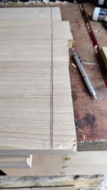
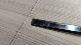
After making a knife wall...

knife_wall.jpg

...the first board got cut off with a 13 TPI cross-cut western tenon saw:

western_saw.jpg

The result ...

after_western_crosscut.jpg

... was a pretty good square cut across the board ...

western_square_one_way.jpg

... but rather less so when looking at it the other way round:

western_less_square.jpg

After doing that one, I switched to a Japanese saw to see how that compared:

japanese_crosscut.jpg

japanese_crosscut_2.jpg

I was surprised at how much faster the Japanese saw cut than the Western one. I don't know whether that's down to sharpness (I've never sharpened the Western one, but when I bought it second-hand in a junk shop, it was still in its box, so I don't think it had been used much from new), or whether its just that the Japanese saws suit me better.

after_japanese_crosscut.jpg

On the first cross-cut with the Japanese saw, I wandered into the waste by about 0.5 mm for the last 50 mm or so of the cut (better that way than the other), but the other three were all pretty square. By the third board, the results were looking pretty good by my standards and quite square to the face:

squarer_last_cut.jpg

After all that, I've got four boards with ends that are somewhere near square:

four_boards.jpg
 
Your later cuts were better than your first one and it's the results that matter, well done.
 
AndyT":1km3dm6c said:
Your later cuts were better than your first one and it's the results that matter, well done.

Thanks Andy.

Not a lot in the way of an update from this afternoon, but out of curiosity, I stacked the boards up on the bench to try to get a sense of scale. It'll be a little bit shallower than this (as I haven't planed the board edges to size yet) and the top will be a bit lower once the dovetails are cut, but it gives a good general idea:

getting_a_sense_of_scale.jpg

I then dug around through the piles of sweet chestnut bits and found some pieces to make up the (thinner) middle support. They're currently planed to just over 16 mm thick (vs 20 mm for the sides and top); I haven't completely decided what size I'll finish them to, but it probably won't be much less than that. This piece serves two purposes: firstly giving some extra support part way along the length of the top to make the top work-surface more rigid and secondly to mount the drawer runners on. I'm thinking of making setting the drawer runners into the uprights (with what I think would be called housing joints), so having a reasonable amount of thickness is required or the two housing joints from each side would cut the board in half!

middle_support.jpg
 
After trimming & planing the middle board (no photos, but some of you will be pleased to hear I sawed both ends with the hand saw!), I decided there were no further excuses available and it was time to start cutting dovetails.

I started by digging out an offcut of oak and marking it up as a "story stick":

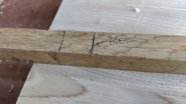
01_story_stick.jpg

There are three (labelled) knife marks: one for a reference position and one for each of the inside dimensions of the box. There are also some pencil marks to give a vague idea of where the ends of the boards should be:

02_story_stick_close_up.jpg

I was feeling paranoid (for which read: untrusting of how square my sawing had been), so I decided to make the tails stick out quite a long way. It'll probably be too much to plane off, but I can always use a flush cut saw to get them somewhere close before planing. Hopefully I won't regret that later on!

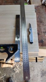
I used the story stick to transfer knife marks onto the rear end of the inside faces of each piece. I then used a square and a 600 mm ruler to transfer the marks along the inside faces.

03_marking_square_lines.jpg

As I was working on the assumption that the ends weren't square, I needed to mark the dovetails from the base line rather than the end. I realise that the angle isn't that critical so I could have just eyeballed it, but I'm very new to cutting dovetails without a crutch saw guide, so every little helps :)

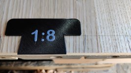
To give me a way to mark them from the baseline, the 3D printer kindly spent 36 minutes making this:

04_dovetail_marker.jpg

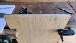
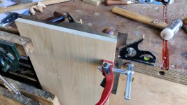
The boards are two wide for the "Moxon" end of my portable workbench, so I clamped them to the normal bench with the vice and a dog hole clamp thing. That made it easy to transfer the marks across the end with a square and cross-out the waste:

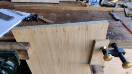
05_marked_up_tails.jpg

To give myself the best chance of something nearing accurate sawing, I tilted the board over such that the lines were vertical.

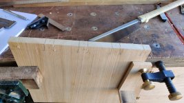
06_angled_sawing.jpg

It was then just a case of taking a deep breath and attacking it with the Dozuki...

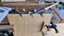
07_tails_sawn.jpg

... and the fret saw:

08_fretsaw.jpg

It then got rotated by 90° and (with a slightly longer read clamp holding it in place), the ends could be sawn:

09_tail_ends.jpg

My 12 mm chisel did most of the work of chopping out the waste, with the 16 mm one coming out for the final cuts.

10_chiselling_tails.jpg
 
It occurred to me that, before I mark the pins, it would be a good idea to check how square my saw cuts had been:

11_checking_tails.jpg

Most were good, but one needed tweaking, so I'm glad I did it!

With that, I was happy to call the tails done:

12_tails_complete.jpg

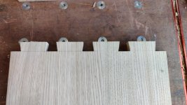
Next up was clamping the bottom board (I'd deliberately chosen to do one of the bottom corner joints first as it would be less visible than the top ones!). Rather than line it up to be flush with the side of my plane, I lined it up to be square with the bench and at about the right height for the plane. That was intended to compensate for any out-of-squareness of the end of the bottom board. Obviously if it were a long way out of square then the marked-up pins would be in the wrong place, but I don't think even I can saw badly enough for that effect to be significant :lol:

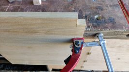
13_setup_for_marking_pins.jpg

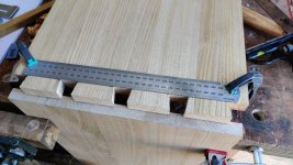
It was then back to my faithful ruler trick, this time using a 300 mm long ruler rather than the usual 150 mm one:

14_ruler_trick.jpg

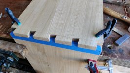
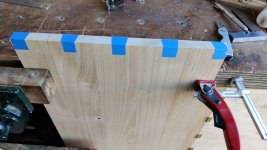
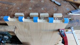
After applying some masking tape to the end of the bottom board, the tail board got flipped over and pushed up to the bottom board until the ruler was in contact all the way along and the back face of each board was aligned:

15_marking_pins.jpg

After squaring the lines up from the base board with the end of a ruler:

16_marked_pins.jpg

Then saw:

17_sawn_pins.jpg

and saw:

18_fretsawn_pins.jpg

then chop, this time with the 16 mm chisel doing most of the work and the 18 mm one taking the final cuts (as a lazy alternative to sharpening the 16 mm one).

It didn't go together straight away and needed a bit of tweaking on two of the pins (one of which I can blame on my other half wandering over and talking to me while I was sawing it!). However, after not much time, the first joint is together. It took a bit of work with the persuading stick to come together so I suspect it's a little on the tight side (to allow for glue), but I'm pretty happy with it for the first go at a dovetail joint in 20 mm ish thick stock without my dovetail saw guide making it easy.

You can see what I mean about going a bit over the top with overhang allowance in this image:

19_fitted.jpg
 
The next few joints proceeded much like the first one so I didn't take many photos. The only differences were:

Rather than marking the tails using the 3D printed gauge thing, I just used the previously cut pieces as a reference:

marking_from_first_tails.jpg

I then cut all of the three tail boards out in one go before using them to mark each of the pin boards. Another small difference is that, after breaking 4 fret saw blades, I switched to the coping saw, which is perhaps more suitable for wood this thick. The coping saw has the disadvantage that it won't go down the kerf of the dozuki, but it's not too big a deal to cut in two passes: middle to left and then middle to right.

After much sawing & chiselling, all the joints were complete and I could do a full test fit (yes, I know Rob prefers not to put dovetails together until they're ready to be glued, but I still like having this crutch!)

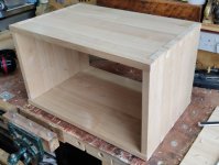
test_fit.jpg

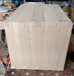
The front edge doesn't line up for the simple reason that I haven't got round to cutting the boards to depth yet; everything was referenced off the back edge, which I decided was more important to be square and flush (as there will be plenty of other things that reference off the back later).

test_fit_2.jpg

I'm really pleased with how that went: hardly any fettling was required to get a tight fit and all that without even using my 3D printed magnetic saw guides! Perhaps I'm getting a little better at sawing?

I haven't quite decided what the next job is. One option is to fit the middle support thingy...

middle_shelf.jpg

... but I haven't figured out how that's going to be mounted yet. The ends will need to be parallel with one another for obvious reasons, which could be made by shooting it square (in which case I could mount it with dowels or a big loose tenon thing). Alternatively, I could make it into a humungous blind tenon, in which case I'd be making the ends square by chopping with a chisel.

Another option for the next task is to cut all the (somewhat daunting) through tenons for the back pieces:

tenons.jpg

These need to be fairly accurate as the back is intended as a reference face (for clamping stuff vertically on the back), although I could possibly just plane down the entire back face after fitting them. Also, I'd obviously prefer that the M&T joints don't look shabby and (apart from a few test cuts in some scrap), I've never made anything with through tenons before. I'll probably wedge the tenons, but I think I can consider that by expanding the mortices after an initial trial fit.

It's all getting gradually more daunting as more hours are sunk into each piece of timber!
 
That's all coming along very nicely.

For the central support thingy, the obvious way would be to cut stopped housing joints. There are a few choices to make - whether to saw the sides or just knife them as you go; whether to make the housings as wide as the support is thick or make it narrower and cut a shoulder on the support.
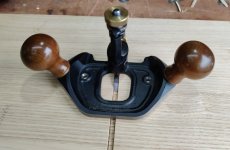
You'd also need to choose which router plane to use.
 
AndyT":20h9pfjj said:
That's all coming along very nicely.

Thanks Andy

AndyT":20h9pfjj said:
For the central support thingy, the obvious way would be to cut stopped housing joints

Thanks, yes: I think I agree with that. I think that's what I meant by the "humungous tenon"; I guess it's effectively the same thing.

AndyT":20h9pfjj said:
There are a few choices to make - whether to saw the sides or just knife them as you go; whether to make the housings as wide as the support is thick or make it narrower and cut a shoulder on the support.

I think I prefer the idea of a shoulder on the support. Without the shoulder, the length of the board has to be exactly right but also not referenced to any of the dimensions on my "story stick": it'll be the inside height of the box plus the depth of the housings. With the shoulder, the only critical dimension is (I think) the distance between the shoulders.

AndyT":20h9pfjj said:
You'd also need to choose which router plane to use.

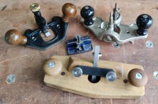
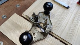
That's also true, although since I sold the Record #71 I've only got four to choose from... :lol:

router_planes.jpg
 
Dr.Al":2q65v6ci said:
........the back is intended as a reference face (for clamping stuff vertically on the back), although I could possibly just plane down the entire back face after fitting them.....

I think that's you're only option. Even the slightest twist in one of the carcase pieces is going to pull that back slightly out of line, even supposing your dovetails are perfect. Do the best you can, but don't over-sweat the back. Clean it up afterwards.
 
Right, onto the housing joints.

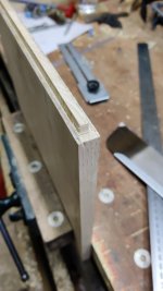
First step was to decide where the central piece would go and mark out the sides of the cut-out. The upright is 15 mm thick, so I'd planned to go with a third of the width, but when I marked a couple of notches, it looked a bit thin, so I upped it a little and went with 6 mm. I've got a 6 mm chisel and a 6 mm router cutter, both of which should help here.

With the notches marked in the base, I transferred them directly across to the top so they should line up nicely:

01_mark_positions.jpg

I then used a square and a long ruler to knife some marks along the sides and I also knifed across the end, although without so much concern for accuracy.

02_knife_lines.jpg

I've never cut a housing joint before (gulp), so I'm not sure if this is the conventional way, but it seemed to work for me...

I started by using a 16 mm chisel to make a wall along the knife line:

03_chisel_wall.jpg

and then along the other knife line:

04_chisel_wall_2.jpg

I then went along the knife line with the chisel hitting down fairly hard with the mallet all the way along:

05_chisel_down_hard.jpg

and then I used the 6 mm chisel to cut into the ends:

06_chisel_ends.jpg

The router plane then worked gradually down to an arbitrarily chosen depth of 8 mm:

07_router.jpg

08_housing_cut.jpg

After cutting the first housing, I set the depth stop on the router plane and then used that as the reference for the depth of the second housing.

09_housing_closeup.jpg

The next job was, fairly obviously, to cut the mating piece, so I started by marking that out:

10_marked_out_central_piece.jpg

To be continued....
 
The board was much bigger than it needed to be, so the first job was to chop it down to (rough) width:

11_sawing_roughly_to_width.jpg

and then sawing it down as close to the line as I could for the length:

12_sawing_end_off.jpg

The length isn't (I think) critical as the shoulders will define the spacing of the top and bottom. The outer knife lines I'd marked on the board were 7.5 mm outside the shoulder lines (for the 8 mm depth of housing). The shoulder lines had been marked from the same story stick that I used when making the sides.

After sawing to the line, the underside still showed a little bit of the knife line towards the end of the cut (which was much better than I expected!), so I trimmed it (and the other end, which wasn't quite square so again had a knife line near the edge) down with a block plane:

13_block_plane.jpg

With that the board was ready for the shoulders to be cut... take a deep breath...

14_ready_to_cut_shoulders.jpg

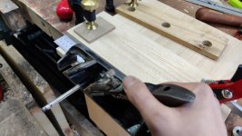
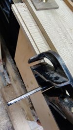
As I tend to get carried away in junk shops that have tools, I have quite a lot of different options for how I might cut this shoulder. After a bit of a ponder, I decided to use my #78 rebate plane, so I started by sharpening the "nicker" (if that's the right name) to help with the cross-cut.

Since I want the shoulder to be accurate and I don't trust my ends to be perfectly square, I wanted to reference off the shoulder line instead of the end, so I got rid of the fence. I then had a bit of a ponder and came up with this:

15_setup_for_roughing_out_shoulders.jpg

The ruler is set (with a knife) to be flush with the knife line.

I started the cut with the ruler in place to keep the plane from wandering:

16_starting_78.jpg

Then, as soon as the edge was defined, I removed the ruler and just worked my way down until the depth stop was touching the board all the way along. I'd deliberately set the depth stop such that the "tenon" would be too thick - this is just a roughing out step:

17_finishing_78.jpg

I then used my other router plane (because why not) along with the offcut that got sawed off this board to bring the first side of both tenons down to the same level:

18_router_to_depth.jpg

I then flipped the board over and brought each tenon to width individually, checking regularly against the mating part.

That worked really well on the first one (fitting into the bottom board), but somehow I managed to lower the router cutter much more than I intended on the second one (fitting into the top board) and that joint is very loose.

I got a set of feeler gauges out and there seems to be a 0.6 mm gap (so I really messed up with the router plane!). I've marked the side of the board that was last to be adjusted (as I want the other side to remain level with it's opposite end) and I think I'll add some sort of spacer in with the tenon to pad out that 0.6 mm. It might be a good chance to practise planing very thin material, although I might have some thin offcuts left from when I made some veneer bookmarks - I think I thicknessed some of them down to 0.8 mm, so it might not take too much effort to get that down the last 0.2 mm.

I suspect what I did wrong was adjust the cutter with the screw pushing it down. I then probably loosened the locking clamp and it dropped through the backlash of the mechanism. What I should have done is adjust it by lowering the screw and then pushing the cutter down onto the nut thing. I'm sure I've made that mistake before and I thought I'd learnt. :oops:

Anyway, with one housing joint fitting beautifully and one fitting extremely loosely, I could trim the tenon things to length with the dozuki (I also tidied it up with a chisel after taking this photo):

19_sawing_ends.jpg

and that's it for now...

20_it_fits.jpg
 
I'm pretty sure I would have just housed out for the entire thickness of the board. It's the same principle as a bookshelf, but on its side. The way you've done it the shoulders have to be absolutely perfect. If you had house out for the thickness of the board, the only things which would have needed to be perfect would be the length of the board, and the dimensions of the housings, and both of those are easily derived using standard woodworking rechniques. What you've done will work nicely, but at the cost of an awful lot more work.
 
That’s very good Al, in fact for a first attempt it’s brill, a strip of good quality card of the Kellogg’s type will fix any sloppiness but just make sure you put it in the right side of the housing- obviously.
Ian
 
Mike G":3rg7dgfb said:
I'm pretty sure I would have just housed out for the entire thickness of the board. It's the same principle as a bookshelf, but on its side. The way you've done it the shoulders have to be absolutely perfect. If you had house out for the thickness of the board, the only things which would have needed to be perfect would be the length of the board, and the dimensions of the housings, and both of those are easily derived using standard woodworking rechniques. What you've done will work nicely, but at the cost of an awful lot more work.

I see what you mean. I was quite concerned about getting the length of the board right and I was also concerned about how good the housings would look (never having done one before) if they were visible rather than hidden underneath the shoulder (note to self: it's a tool chest FFS; stop worrying about what it looks like so much!)

A bit more work isn't a problem anyway: this is as much about the process as the end product and I'm enjoying learning new techniques and figuring out what works and what doesn't.

Cabinetman":3rg7dgfb said:
That’s very good Al, in fact for a first attempt it’s brill, a strip of good quality card of the Kellogg’s type will fix any sloppiness but just make sure you put it in the right side of the housing- obviously.
Ian

Thanks Ian.

I hadn't thought of using card: that's a great idea. As soon as I realised what I'd done, I wrote "+ 0.6 mm" on the over-cut side, so hopefully I won't manage to fit it on the wrong side.
 
The next job was to start working on the (ten) mortice and tenon joints that make up the back pieces:

file.php


I used blind mortice-and-tenon joints on my side table, but the tenons were cut on the table saw and the blind mortices were a lot more forgiving than the through (and probably wedged) ones I'm going to use here.

I had a few practices on some bits of scrap. Most of them looked awful :lol: but one looked okay-ish, so I'm going to use the method that I used on the okay-ish one. I've just finished the first joint and (apart from one small mistake, which I think I can deal with), it went pretty well I think.

The next few posts will describe what I did (I've got 32 photos to show, so I'm not going to get it all in one post!) If you're not interested in reading and seeing exhaustive detail on how I cut one joint, look away now :D

Please remember that I'm not aiming for this to be a fast and efficient process, I just want the result to be good at the end. I'm sure there are quicker ways of doing things, but that's not what this is about for me.

Right, with the disclaimers out the way, let's get started....

All of the back pieces that I'd planed flat and square were random lengths so the first job was do something about that. I trimmed them slightly over length using the Ryoba and my portable workbench:
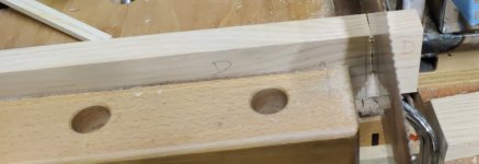
01_trim_to_length.jpg

I then shot the ends square. This isn't strictly necessary as they're over length so the ends will get cut off later, but it makes one bit of marking up a bit easier later on (and I quite enjoy using the shooting board):
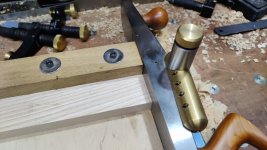
02_shoot_square.jpg

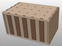
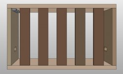
I then sketched out where the back pieces were going to go. This took a bit of thinking about. The CAD model has them spaced so that their centres are on a 96 mm pitch. When I drill the 20 mm holes in the centres of each back piece (as shown in the image at the top of the post) then it'll allow me to use various (mostly 3D printed) widgets that sit in 20 mm diameter, 96 mm pitch holes.

However, the chest isn't quite the same size as originally planned as I just made it the size that the wood came out. With the (admittedly quite small) changes, I worked out that it made more sense for the planks to be spread out on a 93 mm pitch. If I put the holes on a 96 mm pitch, the ones on the end uprights will be 9 mm from one edge of the upright and 21 mm from the other edge, which I guess might look odd, but I've got two options:

  • Put up with it looking a bit odd.
  • Put the holes on a 93 mm pitch instead: most of their use will probably be with simple (single hole) clamps rather than things with a fixed pitch.

Anyway, I've put that on the think-about-it-later pile :)

The next choice was to decide how big the tenons are going to be. The cross-section of the uprights is 20 mm × 50 mm. Going with a width of about a third would imply 6.66 mm. I've got mortice chisels in 6 mm and 8 mm, but I'm making the conscious decision not to make the mortice exactly the same size as a mortice chisel (the one practice piece where everything worked really well was the one where I pared the mortice to width). To make things simple then, I rounded the third up and went with a width of 7 mm. Rather arbitrarily, I decided on 5 mm in from the end on the wider dimension.

Having decided the spacing, I used a pencil to roughly mark out where everything was going to go and used a knife to put some notches in the edge of the board where the ends of the mortice will sit:
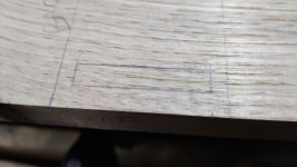
03_pencil_marks.jpg

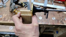
I then set my Stanley router plane to the dimension from the edge of the board to the nearest side of the mortice and used it as a makeshift marking gauge (on both sides of the both the top and the base board):
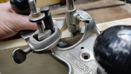
04_router_gauge.jpg

I used a normal marking gauge to cut a line for the far side of the mortice:
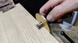
05_normal_gauge.jpg

The notches I'd marked in the edge of the base board 5 mm in from where the edges of the uprights should go were then used to knife the ends of the mortices. I also used the notches to transfer the positions of the ends of the mortices from the base board to the top board so I could knife the ends of the mortices there as well.
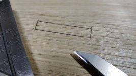
06_knifed.jpg

An offcut from my test runs was also marked with the "router gauge":
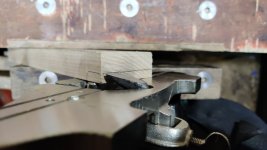
07_router_gauge_on_offcut.jpg

A square knife line was marked about 18 mm from the end of the offcut and then I sawed out the cheek and chiselled down the base line:
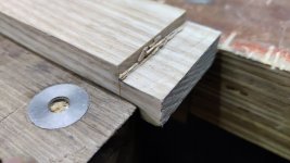
08_chisel_edge_of_offcut.jpg

I then used my Veritas router plane to rough out most of the material until I was just above the gauge line, at which point I set the depth stop so I'd come down to the same point next time I do this:
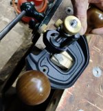
09_offcut_veritas_roughing.jpg

The Stanley router plane could then be used to take the final cuts at exactly the right depth:
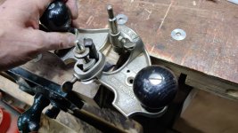
10_offcut_stanley_finishing.jpg

Finally, I roughly sawed the end piece off about 50 mm (at a wild guess) from the base of the offcut's rebate.
 
The next job was to cut the mortice. It seemed sensible to start on the base board as these M&T joints will be out of sight when the chest is finished. Hopefully I'll have mastered the art by the time I get onto the top piece mortices!

I started on the inside face and, using my 6 mm chisel (for the 7 mm mortice), I roughed it out down to a depth of about 15 mm (on the 20 mm base board):

11_mortice_chisel_inside.jpg

I then flipped the board over and used a 5 mm bevel-edge chisel to pop that last 5 mm depth out, leaving about 1 mm all the way around the mortice.

12_5mm_bevel_chisel_outside.jpg

I then flipped the board over again and took out the last bit at the ends of the mortice, again down to 15 mm depth.

13_mortice_chisel_inside.jpg

I then flipped it over again and clamped that offcut that I'd cut onto the board for use as a paring guide:

14_offcut_clamped.jpg

My faithful 16 mm chisel then trimmed the last little bit off:

15_paring_with_offcut.jpg

For the other side of the mortice, I just used the marking gauge line and pared it by eye:

16_paring_other_side.jpg

I also pared in from the other side (using the knife lines for both edges) so that the paring cuts from the outside face didn't blow out the inside face and into my bench (not that my bench is short of chisel marks)

That went well, except that I made one mistake when paring one side of the outside face of the mortice: I moved my chisel too far along the edge and the bevel dug into the end mark:

17_slot_finished_with_mistake.jpg

That's a bit annoying, but I'm planning to wedge these tenons, so I'll probably open the outer side of the mortices a little for the wedges to push into. That will involve removing the bit of wood where that mistake sits, so the error will (hopefully) be rectified (and hopefully I won't introduce any new errors in the process!)
 
Next up was the tenon on the upright. First of all, I used my story stick to mark the length between the shoulders (which should match the length between the bottoms of the dovetails on the sides, which were marked from the same story stick):

20_story_stick.jpg

I then used a square and a knife to mark all the way around the shoulders;

21_knifed_round.jpg

The cheeks could then be marked all the way round with the "router gauge" and marking gauge. I didn't bother marking the width of the tenon yet, that comes later:

22_marked_with_router_and_gauge.jpg

I decided to use my junk-shop-find Pax tenon saw to cut the cheeks, staying a millimetre or so away from the lines:

23_sawing_cheeks.jpg

I'll probably do some of the other tenons with Japanese saws, but it's nice to try different approaches sometimes.

The cheeks were then cross-cut in the vice using the same saw (which is sharpened for cross-cutting, so I guess this is a more appropriate use, but it worked well for both cuts). Again, I stayed a millimetre-ish away from the line:

24_sawn_cheeks.jpg

Next up was trimming the outer side of the tenon down to size. I'd kept hold of the offcut of each piece when I sawed them to length, so I plonked that on the bench by the tenon-to-be:

25_offcut_as_rest.jpg

I then used the Veritas router plane to do the heavy lifting, gradually lowering the cutter until I hit the depth stop:

26_roughing_veritas.jpg

Then the Stanley one took the final pass:

27_finishing_stanley.jpg

Finally, the 16 mm chisel came out again to cut the shoulder line:

28_chiselling_walls.jpg

For the other side, I just used the Veritas router plane (although I had my Paul Sellers one to hand in case it wouldn't cut deep enough as I didn't really want to move the depth stop, although it wouldn't have mattered that much if I had to). I gradually lowered the cutter and took light passes until it was a snug fit in the mortice:

29_test_fit.jpg
 
To set the width of the tenon, I started by setting another marking gauge up for a 5 mm mark and used that to mark one side of the tenon:

30_marking_5mm_edge.jpg

I then used the notches in the base board (the ones I'd used to transfer the marks round to the other side and also to transfer the marks to the top board) to create a small mark on the end of the tenon for the other side:

31_transferring_notches.jpg

As I'd shot the ends of the upright piece square, I could then use a combination square and knife to transfer that notch down the cheek.

A bit of sawing and chiselling later and the tenon was finished. I under-cut the shoulder slightly with a chisel to make sure it would sit flush.

32_finished_tenon.jpg

All that was left was a test fit and I was very happy that it slid in with a very firm push and the back faces are perfectly flush (a result of using the Stanley router plane as a reference for everything including the paring guide):

33_flush_face.jpg

The tenon pops out of its hole looking pretty good too:

34_fitted.jpg

and so completes the dry-fit of my first ever through mortice and tenon on a real project. There's plenty more to do to sort out the wedging and I won't know for sure what it looks like until it's glued up, trimmed to length and planed flush, but so far, so good. Only 9 more to go :D

For the remainder, I'll probably cut all 9 mortices in one go (or maybe do all the remaining base board ones and then later all the top board ones) and then rough out all the tenons and finally bring them to size one-by-one, but we shall see. If they all go as well as the first one, I'll be a happy bunny.
 
... and in considerably less time than it took me to upload all those photos and write all that waffle, the remaining base board mortices are now all done:

35_base_mortices.jpg
 
That’s a very good result for your first m and t, suggest you buy a mortice guage which you can set to the chisel width, press the two points into the wood at the end of the mortice nearest to you and then pull back till the points drop into those holes, a pin type guage won’t follow the grain like a wheel one is prone to, you can mark and chop from both sides of the plank.
Then you can use the same chisel you set the guage to to remove the wood between the lines, this will save you quite a bit of time.
Ian
Edit too late lol.
 
Cabinetman":11brxkmj said:
That’s a very good result for your first m and t, suggest you buy a mortice guage which you can set to the chisel width, press the two points into the wood at the end of the mortice nearest to you and then pull back till the points drop into those holes, a pin type guage won’t follow the grain like a wheel one is prone to, you can mark and chop from both sides of the plank.
Then you can use the same chisel you set the guage to to remove the wood between the lines, this will save you quite a bit of time.
Ian
Edit too late lol.

I've got two mortice gauges: a pin one & a wheel one. I used both (not at the same time!) on practice pieces, setting the gauges to chisel size and "doing it properly". That's also how I cut the blind mortices on the side table.

On the practice through mortices where I was mortice-chiselling directly to size, the mortising took longer (due to having to pay more attention to be accurate) and the face side ended up with a gap (albeit a small one) around the tenon. The paring step doesn't take long at all (probably takes less time than is added to the mortising stage), so at the moment I'd rather stick with this approach. The practice pieces where I pared the mortice were all better than the best one where I mortised to size.

Anyway, the router gauge thing guarantees the faces are flush and that's important to me, so a mortice gauge wouldn't work as well for this specific application I think.
 
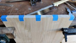
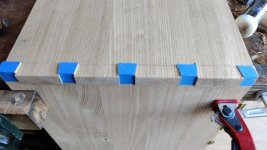
This morning I cut the mortices in the top board and then cut all of the tenons:

tenons_all_cut.jpg

I slightly messed up one of them: I was a bit careless with the chisel and the tenon is slightly too narrow at the outer edge. It's only a very small offset (about a millimetre), so I'm currently thinking I'll just live with it and make the wedge for that one a bit thicker to compensate.
I'm now trying to think about wedge angles and how far in from the ends of the tenon to cut the slots for the wedges. I'm assuming it's best to make the wedges at a slightly steeper angle than the edges of the mortices (so that the wedges definitely push the ends of the tenons into the ends of the mortices), but I'd welcome any and all advice on this!

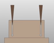
In case it's not clear what I'm talking about, this is the sort of thing I'm planning to do:

wedge_drawing.jpg

Things I'm not sure about are:

  1. How far from the (left and right) edges to cut the slot
  2. What angle to put on the wedge
  3. What angle to put on the extra bit I cut out of the mortice at each end
  4. Anything else I need to be aware of!
 
With your questions about wedges, you could get quite a few different answers. It's a subject that various writers in books and magazines have disagreed loudly about for the last century or more...

But, to offer some very broad generalisations:

M&T joints on this sort of scale don't need to be wedged to be effective.
If you want to put decorative wedges within the tenons, just go by eye. Keep them slim and allow enough space for the wood to spread into without needing to be crushed. I'm sure you will measure it carefully.
This sort of decorative wedge was popular in some Arts and Crafts style cabinetry.

Wedged tenons in joinery work (ie in doors and windows) are only ever found on the outsides of the tenons. No time is spent cutting slits in the tenons. The mortises do get chiselled back a bit but not all the way through to the other edge.
On a door or window, selectively knocking in the wedges is how you can make sure the whole thing is square - or if it's done wrong, can make good work go crooked.
If you want more controversy, you could look into where the glue should go - over everywhere, just towards the shoulders, or just at the ends of the tenons. ;)
 
Thanks Andy...

AndyT":2xtakmvm said:
With your questions about wedges, you could get quite a few different answers. It's a subject that various writers in books and magazines have disagreed loudly about for the last century or more...

Oh goody :lol:

AndyT":2xtakmvm said:
M&T joints on this sort of scale don't need to be wedged to be effective.

Is there a disadvantage to doing so? My feeling is that they'll look a lot better with wedges (partly because I know there will be places where I haven't cut the tenon length quite right and the wedge will hide the evidence).

AndyT":2xtakmvm said:
If you want to put decorative wedges within the tenons, just go by eye. Keep them slim and allow enough space for the wood to spread into without needing to be crushed. I'm sure you will measure it carefully.

Good advice, thanks

AndyT":2xtakmvm said:
This sort of decorative wedge was popular in some Arts and Crafts style cabinetry.

Wedged tenons in joinery work (ie in doors and windows) are only ever found on the outsides of the tenons. No time is spent cutting slits in the tenons. The mortises do get chiselled back a bit but not all the way through to the other edge.

That's interesting, I hadn't seen wedges outside of the tenon before; it felt intuitively to me that the wedges would be more effective if shoved into the tenon itself, but what do I know?!

Do you think there's an advantage one way or the other?

AndyT":2xtakmvm said:
On a door or window, selectively knocking in the wedges is how you can make sure the whole thing is square - or if it's done wrong, can make good work go crooked.

I hadn't realised it could have that effect. I'd assumed that, as long as the tenon shoulders were flush, the wedges would only act as a securing thing. Now I'm even more nervous about putting it all together :D

AndyT":2xtakmvm said:
If you want more controversy, you could look into where the glue should go - over everywhere, just towards the shoulders, or just at the ends of the tenons. ;)

Wherever it feels right when I'm in the mad panic of gluing it all together perhaps? :D
 
I should have also said, that on the scale of your box, I'm sure that what you plan will be ok. With all those joints, it won't have as much freedom to go out of square as a big empty window sash would, but you won't be bashing at the wedges with your biggest hammer, at least I hope you won't!

If I can drag up any of the old magazine discussion/controversy, I'll start a separate thread.
 
While I think about wedges, another thing I've started pondering about is all those holes.

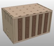
As I mentioned a few posts back, I changed the spacing of the back slats such that they're no longer 96 mm pitch. If I put 96 mm pitch holes in them, they'll be off-centre on the outer ones, something like this:

closed_back.jpg

As I said before, one option is simply to switch to 93 mm pitch.

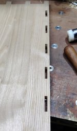
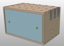
However, one of the changes I made since starting the design was to add the planing stops at the end of the board (you can see the cut-outs in the dovetails for them on the left of the image above). Those planing stops should do a lot of the work that the holes in the top were originally intended for.

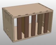
One option that I have that's starting to feel quite appealing is to get rid of the holes completely and also get rid of the thin filler pieces that go between the uprights on the back. I could then just put clamps through the gaps in the back or the opening at the front to clamp stuff to the top when needed.

I need to think a bit more about anything I might have missed that would screw up this idea (your thoughts, dear reader, are welcome as always), but I thought I'd scheme it out in CAD to see what it looked like:

open_back.jpg

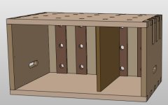
Another view (also showing the thingies that the planing stops will screw to so that the planing force is acting on the top rather than trying to pull the dovetails apart):

open_back_2.jpg

Of course, making a change like that isn't as simply as omitting the holes and the grooves for the thin back pieces. At the moment, the shooting board is designed to act as the front of the chest. It has some little knob things that lock it into place. When the shooting board is used, it drops onto the top of the chest and those knobs are conveniently located such that they drop into the holes in the top. That won't work very well if the holes aren't there :lol:

shooting_board_in_place.jpg

I'm sure I can come up with an alternative locking mechanism, but it's another thing that needs to be thought about.
 
AndyT":2yqi8mml said:
I should have also said, that on the scale of your box, I'm sure that what you plan will be ok.

That's really good to know, thanks.

AndyT":2yqi8mml said:
With all those joints, it won't have as much freedom to go out of square as a big empty window sash would, but you won't be bashing at the wedges with your biggest hammer, at least I hope you won't!

I won't be now that you've said that :lol:
 
Cabinetman":1qmuc2sl said:
I do hope your chest won’t rack when planing on it Al, don’t suppose you will be doing a whole lot of heavy planing anyway, that shooting board should stop quite a bit of it.
Ian

I hope not too! I guess that would be one argument for keeping the intermediate pieces in as they would help stop the racking. If it racks enough that the shooting board helps, then I suspect the shooting board would get jammed in there, which wouldn't be great.

I'm not sure what I can do to make that better though :eusa-think:

I'm only planning to make stuff on the scale of boxes while I'm away, but I guess the sides of a box can still need a fair bit of planing effort.
 
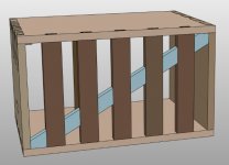
I think this would stop the risk of racking, but I also think it would be nigh-on impossible for me to make :D

racking.jpg

Fun to think about though...
 
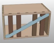
Actually, if I did it with half-lap joints, it might be possible to cut (as I could make it after assembling the chest I think). I've no idea whether it would cause problems with wood movement or anything else though :?

half_lap.jpg
 
I seem to have found myself in a situation where I've got lots of questions to answer about how I'm going to do things: wedge position and size, whether to have holes or not, whether to have the thin infill pieces and now Ian's also got me worrying about racking :D

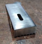
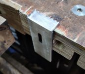
For a bit of light relief, I thought I'd have a go at making the first planing stop out of some 5 mm stainless steel flat bar.

planing_stop_1.jpg

planing_stop_2.jpg
 
That looks the business! Is it welded together? Is that another of your useful skills?
 
AndyT":rrt3mblo said:
That looks the business! Is it welded together? Is that another of your useful skills?

Yes, it's a bit of 40 mm × 5 mm stainless bar from which I cut a 100 mm length and a 20 mm length. The 100 mm length got a slot cut into it (the original plan you might be able to see in some of the models was to have a countersunk slot, but once I decided to make it out of stainless steel, I gave up on that idea as stainless steel is pretty unpleasant to mill). It also got a heavy chamfer on the end. The 20 mm length had the teeth cut into it. I then TIG-welded them and cleaned it all up with a flap-disk in an angle grinder.

I didn't take any photos during the process, but I might do so when I make the other two.
 
Back
Top