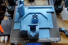
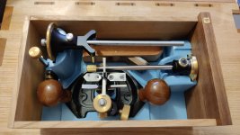
• Hi all and welcome to TheWoodHaven2 brought into the 21st Century, kicking and screaming! We all have Alasdair to thank for the vast bulk of the heavy lifting to get us here, no more so than me because he's taken away a huge burden of responsibility from my shoulders and brought us to this new shiny home, with all your previous content (hopefully) still intact! Please peruse and feed back. There is still plenty to do, like changing the colour scheme, adding the banner graphic, tweaking the odd setting here and there so I have added a new thread in the 'Technical Issues, Bugs and Feature Requests' forum for you to add any issues you find, any missing settings or just anything you'd like to see added/removed from the feature set that Xenforo offers. We will get to everything over the coming weeks so please be patient, but add anything at all to the thread I mention above and we promise to get to them over the next few days/weeks/months. In the meantime, please enjoy!

Holiday Toolchest

Andyp":2bbxipj5 said:
AJB is Adrian BTW but I do agree with his comment.

Whoops. Sorry Adrian, I should have known that. I've edited my post.

Andyp":2bbxipj5 said:
Have you considered a small caravan to tow behind that Passat. With a small geni you could then take the lathe on holiday too. ;) :) And the 3D printer :shock:

Now you're just being silly :lol: :lol:

In all seriousness though, this project was as much about the process as the end result. The idea of having the ability to carry a small workshop around with me for use on holiday while my other half needs to rest (for M.E. reasons) definitely has a strong appeal, but I could have possibly achieved that by getting into chip carving or something like that.

I really wanted something that would stretch my limited hand tool skills and give me an opportunity to learn as many new techniques as possible. I also wanted something that would give me enough practice at some of the core techniques (in particular, preparing planed boards from rough stock and cutting dovetail joints) that I could approach them with more confidence in the future. Given how quickly I made the last drawer (albeit from stock I had previously planed to thickness when making the previous ones), it's definitely achieved the goal of making me more confident at dovetails.

This project has given me loads of practice and experience at a lot of different types of woodwork while not having to worry unduly over aesthetics (which I don't find comes especially naturally to me). Although I'm sure it'll go on holiday with me for a few years yet, it's arguably academic whether it gets used: if it spends the rest of its life stored out the way, it still will have achieved the goal of helping me learn the techniques.

I've also enjoyed the process and that's even more important I think.
 
Enjoyment is good. But it is clear you have not understood the point of holidays, therefore your operating system needs a reset.

The ONLY tool required on holiday (if you really must) is a pen knife. This is used for whittling for which you just need a stick. These are always readily available locally - just ask the nearest dog.

As a slight aside my father always secreted a pen knife about his person "just in case". It was unfortunately confiscated when he went to the Vatican and the pope's gang never returned it. Would probably have been OK to take a stick though.
 
AJB Temple":21ij6mng said:
As a slight aside my father always secreted a pen knife about his person "just in case". It was unfortunately confiscated when he went to the Vatican and the pope's gang never returned it. Would probably have been OK to take a stick though.

Mine got confiscated at the London Eye (they didn't like that it was a locking one, which I find much safer to use but isn't entirely legal) :oops:

Its replacement now gets left behind on the extremely infrequent occasions when I go into a city.
 
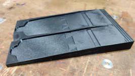
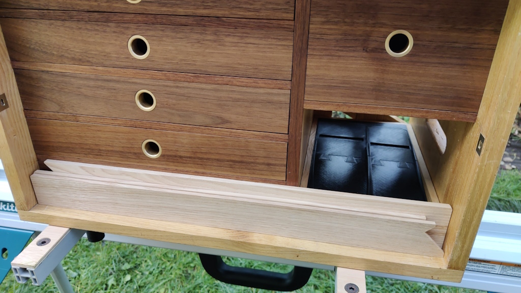
The plane tote drawer insert thing has finished 3D printing now (with cut-outs for protruding blades; merci Monsieur P for the suggestion).

01_plane_tote.jpg

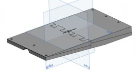
It's printed in 4 main parts, partly because of the limited size of the bed of the 3D printer and partly to make sure that the top surface was nice and smooth. There are also some small (hidden) alignment pins and a thin alignment strip that stop top and bottom bits wandering apart (not that I can think why they would). The construction is probably more obvious from the CAD model:

construction.jpg

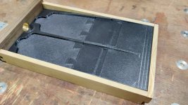
It fits the new drawer nicely:

02_fitted.jpg

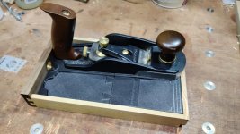
This shows how the long smoothing plane overhangs the drawer:

03_with_plane.jpg

In parallel with the print jobs, I decided to revisit something that's been bugging me for several months. You may remember that, when I oiled the box back in June-ish, a crack appeared that I hadn't seen before:

c01_crack.jpg

The hope was that it would close up with time, but it hasn't and it's a little unsightly. I've never tried fitting a grain-matched Dutchman before (the one on the back of the chest was just a random bit of chestnut and the butterfly things on the shooting board were in a contrasting wood). I wasn't really sure how to go about it, but I thought I'd try my best and see what happens. This was what I did (I'd be interested to hear if there are good alternative approaches to getting the grain match right).

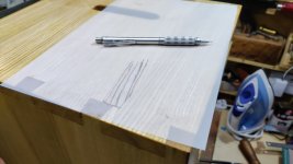
I started by laying a bit of tracing paper over the side of the chest and using a pencil to draw the grain onto the paper:

c02_tracing.jpg

(disclaimer: that photo was taken after fitting the Dutchman as I realised I hadn't taken one at the time actually did the tracing!)

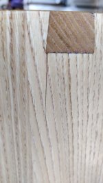
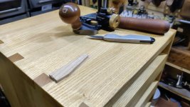
I then searched through the pile of offcuts until I found something that matched relatively well. I cut it out, planed the sides at a slight angle (thanks Mike G), traced around it with a knife and cut the shape out with chisels and router plane. Glue and some light hammering got it to this stage:

c03_insert.jpg

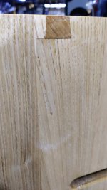
Then it was just a case of planing it down with a smoothing plane and reapplying Mike's Magic Mix:

c04_finished.jpg

For a first attempt at a discrete Dutchman, I was really pleased with that.
 
I know this is a practice piece, Al, and that Dutchman looks fine.......but I think a more realistic repair might have been either filler, or a thin sliver inserted in the crack. Even possibly a bit of inlay a few mm wide (a really narrow Dutchman, if you like). The thing which gives Dutchmen away is the cross-grain cut at the ends, so keeping that to a minimum is ideal.
 
I think that looks really good.

The tracing paper idea is one of those simple things that seem so sensible and obvious, but only after someone else has had the intelligence to suggest it. Nice one!
 
Mike G":32tummvu said:
I know this is a practice piece, Al, and that Dutchman looks fine.......but I think a more realistic repair might have been either filler, or a thin sliver inserted in the crack. Even possibly a bit of inlay a few mm wide (a really narrow Dutchman, if you like). The thing which gives Dutchmen away is the cross-grain cut at the ends, so keeping that to a minimum is ideal.

Thanks Mike, that's useful advice. I suspect filler might not have stuck very well (without removing at least some extra wood): I only saw the crack after oiling it and I doubt the filler would have stuck to the oiled surface very well. The really narrow Dutchman is definitely worth bearing in mind for future. The crack went right to the corner of the dovetail, so I felt I had to make the Dutchman overhang the corner a bit, which inevitably led to the visible cross-grain cut.

Cabinetman":32tummvu said:
Yes pretty good, only you know how much too tight it was when you put it together to cause it to do that Al, or was there a crack just there in the wood anyway waiting to trip you up?

I honestly have no idea. It felt like it went together relatively easily, but I'm not sure my "relatively easily" is well-calibrated.

AndyT":32tummvu said:
I think that looks really good.

The tracing paper idea is one of those simple things that seem so sensible and obvious, but only after someone else has had the intelligence to suggest it. Nice one!

Thanks Andy.
 
A major landmark was achieved today.

Over the last couple of weeks, I've oiled all the drawers (Mike's Magic Mix as usual) and then left them in the house for the oil to thoroughly dry. Yesterday I did two relatively minor things:

  1. Made a "7" badge for the new plane-tote-drawer-thing for consistency with the other six drawers.
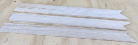
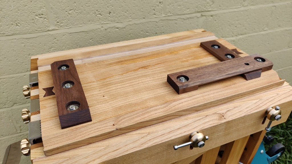
  2. Made a set of three "doe's feet" in different thicknesses. I don't really need three of them, but the thinner ones will be useful when working on thin stock while the thicker ones will be more robust. I can see myself using more than one: one holding the corner in the normal way and one as a general stop (using the non-doe's-foot end). However, the main reason I made three was that the thickness of the three adds up to just the right amount to stop the bottom drawers moving forward. If I think of a better thing to use the space for, it'll be easy to change it.

01_does_feet.jpg

That might not seem like a very major landmark. However, if you ignore all the 3D CAD modelling and 3D printing that's going to be required to make all the inserts for the drawers (and which will probably take me a long, long time to get through), I think I can call the chest finished.

:obscene-drinkingbuddies:

From first cut to completion has taken me 11 months; from first CAD model to completion more like 18.

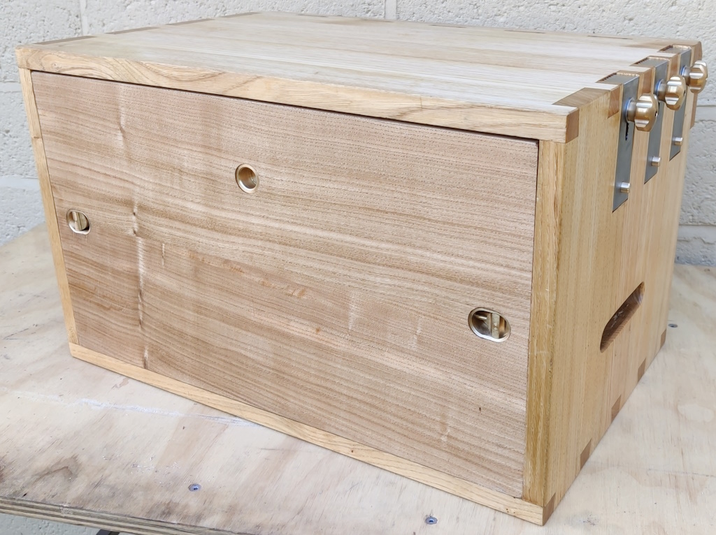
The last thing to do was take a lot of photos, so here they are:

Front view:

with_front_on.jpg


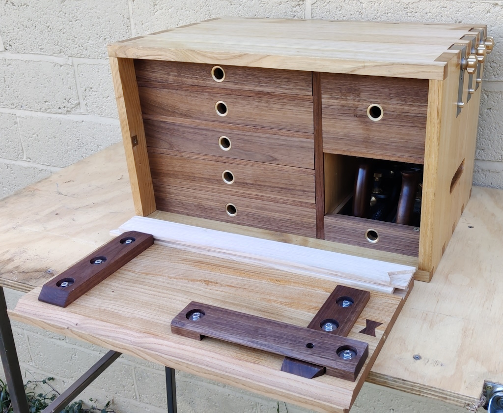
Front open, showing the doe's feet tucked in place:

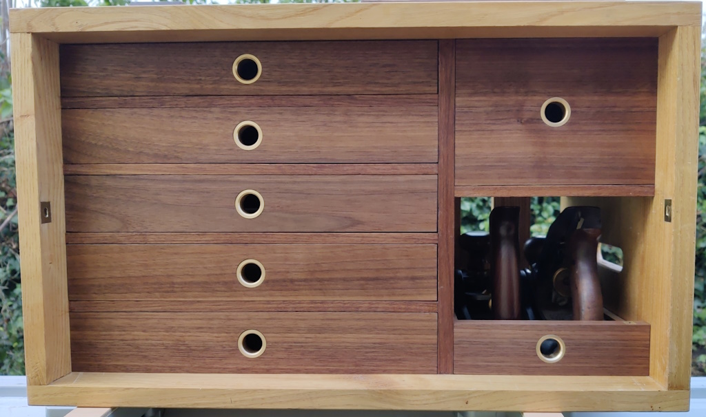
just_opened.jpg


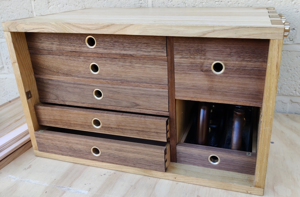
More views of the oiled drawers in place:

front_with_drawers_slightly_open.jpg


front_view_with_shooting_board_removed.jpg


This is where the doe's feet go:

does_feet_tucked_in.jpg


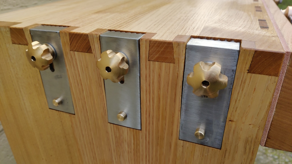
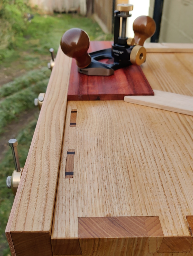
Planing stops:

planing_stops_close_up.jpg


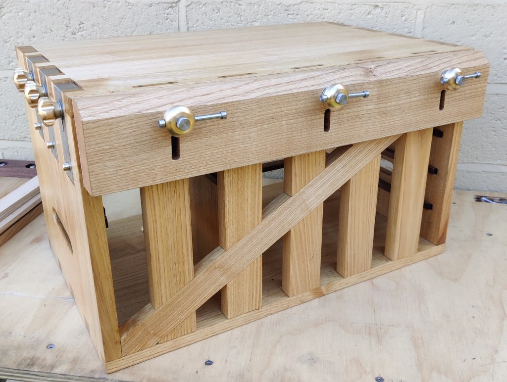
Back view:

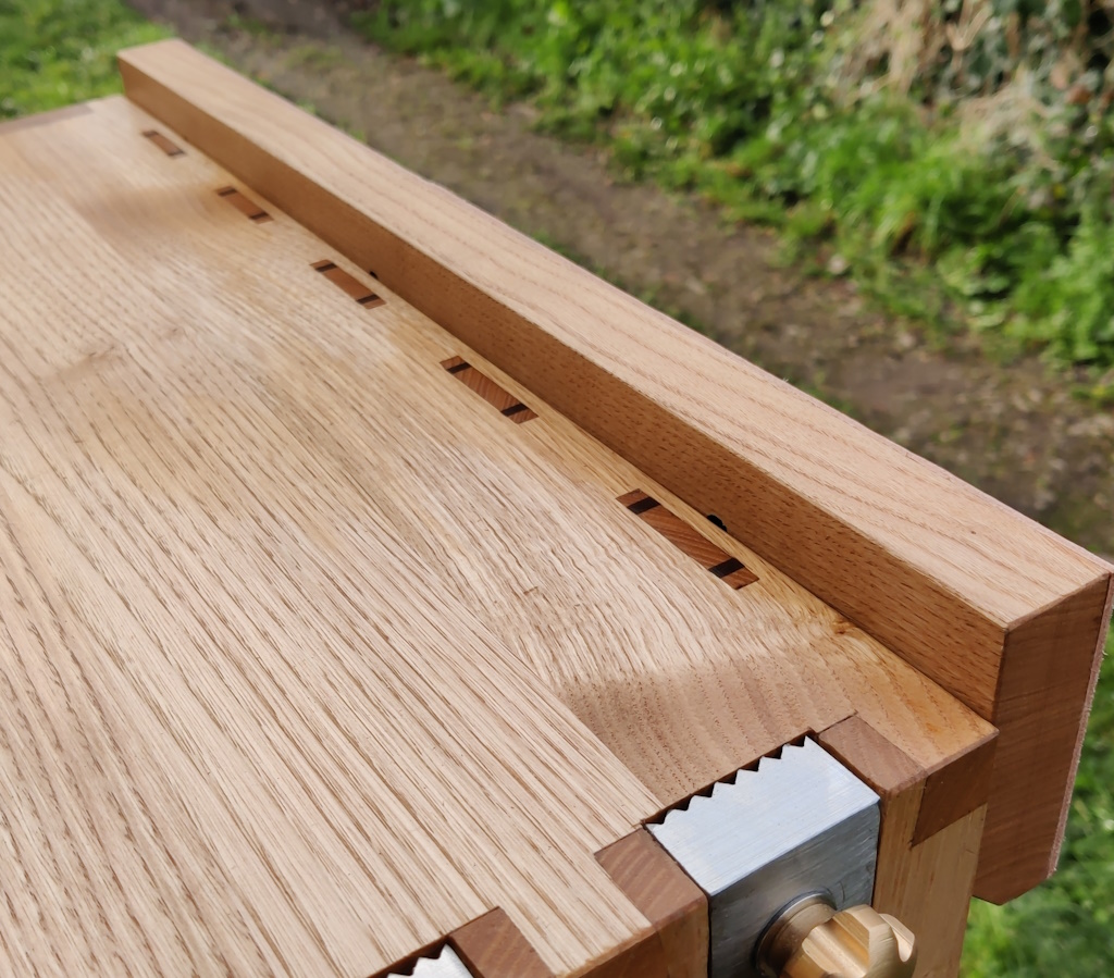
rear_view_showing_vice.jpg


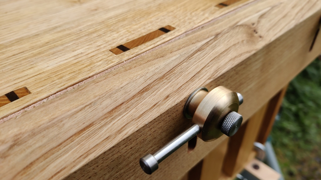
Close-up of the vice screw and a wedged tenon:

wedged_tenon_and_vice_screw.jpg


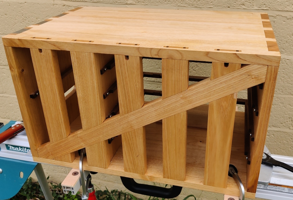
View showing the whole of the back with the anti-racking piece:

anti_racking.jpg


I also took the opportunity to take some photos of the various different work-holding methods that are available.

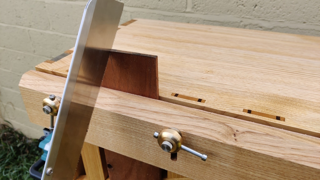
Holding a piece in the vice for sawing:

sawing_vertically.jpg


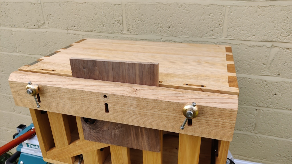
Removing the middle vice screw and holding a wider piece:

wide_board.jpg


The vice jaw can be completely removed and then really big pieces can be clamped to the back for sawing to length or edge planing:

clamping_to_back.jpg


or clamped to the top for sawing or chiselling or whatever:

clamping_to_top.jpg


The planing stops can be used for simple face planing:

face_planing.jpg


Or for a bit more robustness, a doe's foot can be clamped to the top:

planing_with_does_foot.jpg


The vice can also be flipped round (so that a solid face is against the chest rather than a leather face) and then moved up and down (this photo shows the upper limit):

fully_raised_stop.jpg


That allows boards to be fully constrained while still giving complete access to the top surface:

access_to_whole_top_surface_2.jpg


access_to_whole_top_surface.jpg


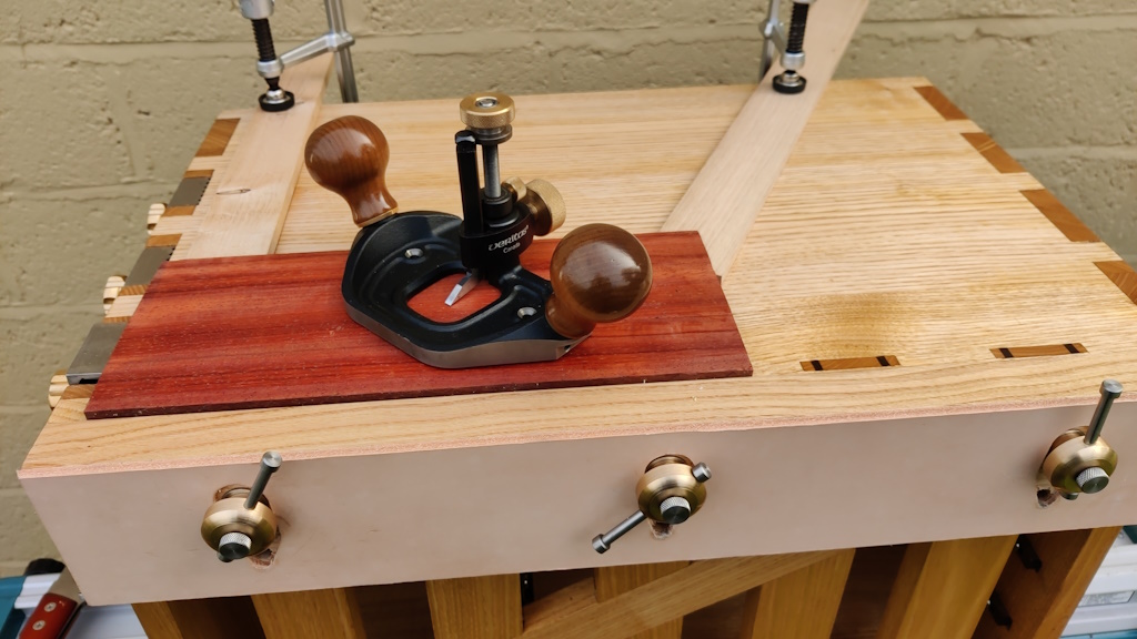
Finally (I think), there's the chest front / shooting board, which goes on top and pushes against the planing stops (this is the main reason for having three planing stops - so one is far enough over to support the shooting board near the working side)...

shooting_on_top.jpg


which can be used for shooting ends square...

shooting_end.jpg


... and shooting mitres:

shooting_mitre.jpg


shooting_mitre_2.jpg


fin.jpg

:)
 
Absolutely excellent!
The only thing left to do is to take it on tour.

Sent from my Redmi Note 9S using Tapatalk
 
Superb. A fascinating insight into how you think about problems and engineer solutions.

I can't remember what you have as a bench in your little shed, but I wonder if this could be built into or joined onto it in some way, for the times when you are holidaying at home, and need the clever workholding and shooting facilities?
 
Malc2098":x8pbj67u said:
Very nice.

Thanks Malc.

Jonathan":x8pbj67u said:
Absolutely excellent!
The only thing left to do is to take it on tour.

Thank you Jonathan.

AndyT":x8pbj67u said:
Superb. A fascinating insight into how you think about problems and engineer solutions.

Thanks Andy

AndyT":x8pbj67u said:
I can't remember what you have as a bench in your little shed, but I wonder if this could be built into or joined onto it in some way, for the times when you are holidaying at home, and need the clever workholding and shooting facilities?

My bench is three bits of plywood glued face-to-face, fixed to the wall at the back and fixed to some bits of scaffolding pole at the front. Putting the tool chest on top of it would result in a work surface that's far too high to be especially useful, but if I need alternative workholding I can always get the mitre saw stand out of the shed and use it with the travel toolchest in the garden (weather permitting obviously).

To be honest though, with the vice and my portable workbench, I don't really need any more workholding methods. It will be very nice to be able to use the portable workbench again: I've really missed it in the last few months (it has had the tool chest sitting on it as that was the only space available!)
 
Going right back to the start of the project, I said that one of the reasons I was doing this was to challenge myself, learn new techniques and get generally better at hand toolery. A few thoughts regarding that aspect:

This was:

  1. The first project in which I've made panels from rough sawn wood by hand. In the past I've made panels, but they've involved a table saw (which I'm very happy to have now sold!) and/or thicknesser (which I've still got, but it's nice to be able to work without it, especially given the amount of snipe from my cheap-ish thicknesser). I've planed wood to size by hand in the past, but only relatively small pieces (for boxes) and this is the first time I've had to make lots of pieces of wood square edged and the same size.
  2. The first project where I've cut dovetails without any sort of saw guide. I've cut quite a lot of dovetails with 3D printed saw guides and I've cut a few (not very successful) dovetails without the guides on bits of scrap wood for practice, but this is the first finished project that includes guide-less dovetails. Also the first time I've cut dovetails on such thick wood: all previous ones have been on box-scale projects, so 10-ish mm thick rather than 20 mm thick.
  3. The first project in which I've cut housing joints (for the middle upright support and the drawer runners).
  4. The first project with wedged through mortice-and-tenon joints (for the rear uprights). I used blind mortice-and-tenons on my side table, but the tenons were cut with a table saw and the fact that the mortices are blind makes them a lot easier! I'd done a few practice joints (with varying levels of success!) in offcuts, but never used them in a project.
  5. The first project with half-lap dovetails (for the drawer fronts). I'd done exactly one practice piece before starting this project.
  6. The first project with wooden drawers. Unless you count pocket-hole joined plywood boxes with ball-bearing slide runner things, I'd never made a wooden drawer before this project.
  7. The first project with half-lap joints (on the anti-racking diagonal piece on the back).
  8. The first project in which I've used protein-based glue (most joints with fish glue and some with TB hide glue).
  9. The first project where I've had to come up with my own way of dealing with wood movement. On previous projects I've just used well-known techniques (buttons for table tops, grooves for box bases), whereas making what is essentially a five sided box where all sides needed to be rigid took a bit more thought. Hopefully what I've done will last.
  10. The first time I've used a "Dutchman" / graving piece to repair a blemish. I used two different types of Dutchman: decorative butterfly ones in a contrasting wood and a discrete grain matched one.
  11. The first large project I've finished without sandpaper. The faces were finished with a smoothing plane without any of the dust and tedium of sanding (and I think it looks a lot better for it!). A scotchbrite pad was used for rubbing between coats of finish ("Mike's Magic Mix": equal parts pure tung oil, satin varnish & white spirit) but that's a quick job compared with sanding large surfaces.
  12. The first time I've tried photolithography (for etching the numbers that are inset into the top of each drawer front to help re-fit them in the right place as they're removed when the tool chest is in use).
  13. The biggest and most complicated hand-tool project (and woodworking project in general) I've done. I did use a bandsaw for some bits of resawing, but all the other woodwork was by hand. Metalwork was all powered, but that doesn't bother me as I hate filing and don't even aspire to being a hand-tool metalworker. Woodwork power tools are noisy and dusty, but most metalwork power tools I use aren't (angle grinders being the obvious exception). Welding the planing stops without some sort of power source would have been quite a challenge!
 
If we gave out prizes for project of the year I feel sure this would win hands down.

Thanks for sharing it with us in such detail.

Just a thought. Are those planing stops and vice handles removable for transit?
 
Andyp":2qg6xt1k said:
If we gave out prizes for project of the year I feel sure this would win hands down.

Awww, thanks :oops:

Andyp":2qg6xt1k said:
Thanks for sharing it with us in such detail.

Just a thought. Are those planing stops and vice handles removable for transit?

They can be removed, but I don't think they need to be. The chest sits on the back seat of the car and the natural shape of the seat means that vice screws are in the gap between the chest and the rear rest of the seat. The planing stop screws just hang out into space, but they don't really get in the way. It would be more of an issue if I was trying to squeeze the chest into a cuboid space, but I'm not.
 
I’m sure most of us have enjoyed the journey.
It’s inspired me to make a few bits and pieces for my workshop.

Looking forward to your next project
 
Lurker":1lx8cxqy said:
I’m sure most of us have enjoyed the journey.
Thanks Lurker.
Lurker":1lx8cxqy said:
It’s inspired me to make a few bits and pieces for my workshop.
I'll look forward to the detailed WIP then :D
Lurker":1lx8cxqy said:
Looking forward to your next project

It might be quite a lot less complicated :lol:
 
A really super piece of work with great attention to detail and design and quality workmanship. I’m sure it will keep you happy and busy on your excursions for years to come.
But Al, what on Earth are you going to do for an encore?
And thank you for the hours of work putting it up for us to see.
Ian
 
I declared this project finished back at the start of December, but that's not strictly true: I've still got to sort out holding the tools in drawers so they don't rattle around all over the place. As I've been in a bit of a workshop slump, not getting much done or feeling especially inspired, I thought I'd have a go at the (quite complex) CAD modelling for a 3D-printed liner for the first drawer.

This is the CAD model at the moment:

model.jpg

It needs work :lol:

Usually when doing this sort of thing, I'd print some very small cut-out bits that I could use to check dimensions and shapes, but this one had so many things I was uncertain about I just decided to print it as-is and try to fix all the various inevitable problems in one go.

It had to be split into two pieces to get it on the printer (the other, bigger drawers, will need four prints per drawer!), but I managed to get both pieces onto the bed at the same time so it could be printed in one go:

print_bed.jpg

As I said, it's far from perfect, but the idea works.

needs_work.jpg

The main thing that needs sorting is the dimensions of the slots for the marking gauges: they stay put (ish), but they don't drop down into the holes in the way I'd intended. Measuring the shape of things like this is a bit of a pain in the proverbial posterior, so I'm not surprised I got it wrong on the first attempt.

Now that I know what needs tweaking, I can do some prints of small sections of it (which will be quicker) to check the adjusted dimensions.
 
I realise this isn't the time to suggest just wrapping the bits in an old t-shirt and stuffing them in, so I won't! :lol:

Very elegant.
 
If you've come here hoping to read about woodwork, please look away now :)

I've tried to document everything involved in this tool chest project in detail. In that spirit, I thought one or two people might possibly be interested in the process of preparing the models for the 3D-printed drawer liners. If that interests you, read on...

The router plane drawer is by far the most complicated one as it involves the third dimension in terms of tool placement as well as tool shape. That design is mostly complete, although a few tweaks are outstanding. It would take me a very long time to describe everything involved in designing that one, so I thought I'd document one of the others. The saw drawer is probably the next most complicated as the saws aren't a simple shape (compared to an engineer's square or a sliding bevel or whatever).

The one thing that makes the saw drawer relatively simple is that there aren't many tools going into the drawer, so it seems to me an ideal candidate for a write-up.

As a quick refresher, this is the drawer with the saws that I want to include:
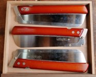
00_photo_of_saws.jpg

Just to make things a bit more complicated :D I'm going to overlap two of the saws. Despite the overlap, I'd like the saws to stay put during ferry crossings without them banging against one another too much. In practice, I'm sure the saws would be fine if they did bang into each other, but I'm going to protect them anyway.

The first thing I did for this drawer was to get a sheet of (A3) paper and draw the drawer outline. I then placed the saws onto that outline and drew carefully around them with a pencil. To get the shape of the handle, I drew around the saw first with the blade closed and then again with the blade open. The two Dozukis turned out to be the same shape, but the Kataba is subtly different.

After drawing round the Dozuki and the Kataba, I also sketched the position of the other Dozuki in two different locations - overlapping as mentioned before and separate. That was just for reference and, as you'll see later, I didn't make any use of those sketches.
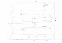
01_scanned_drawing.jpg

Note the little crosses that correspond with the location of the blade-retention screws (which result in the blade being thicker in that area).

With the drawing prepared, I scanned it into the computer and loaded into OnShape. I created a new "Part Studio" and started by sketching a rectangle to match the inner size of the drawer and extruding it 1 mm thick. I then created a new sketch on the face of that base plate and inserted the scanned drawing.

I had marked some known dimensions on the drawing, so I could scale the image until the dimensions were correct. I then used the "Spline" tool to draw around the saw handle profiles, erring on the side of being outside of the profile so that the resulting body is too large rather than too small:
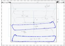
02_draw_round_bodies.jpg

That sketch could then be extruded to the measured thickness of the saw handles (20 mm). I did the extrude operation as a symmetric one, so the initial sketch plane ended up in the middle of the handles:
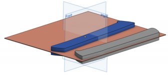
03_extrude_symmetric.jpg

I'd measured the radius of the curve on the edge of the handles using some 3D-printed radius gauges. With that number in hand (10 mm radius), I could fillet the edges of the handle:
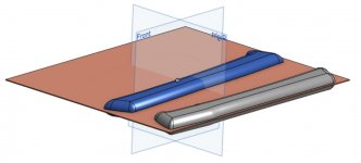
04_fillet.jpg

I could then create another sketch on the same face as the previous one, this time drawing splines around the blades:
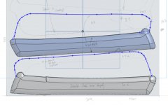
05_draw_round_blades.jpg

As with the previous extrude, I did a symmetric extrude again (3.5 mm this time, to correspond to the spine thickness). As both extrudes were symmetric about the same plane, the blade ended up in the middle of the body. I also created a simple sketch with just two circles, one in each of the screw locations and with the circle diameter quite a bit bigger than the screw head diameter (in case the position wasn't quite right). That got extruded as well and the end result was two models of saws and a base plate:
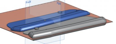
06_extruded_blades_and_screws.jpg

With that done, it was just a case of duplicating the Dozuki model and doing X, Y, Z and rotation transforms to drag them around until I was happy with where they sat:
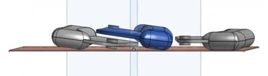
07_duplicate_dozuki_and_move_around.jpg

The base plate was then thickened until it came half-way up each of the saws...
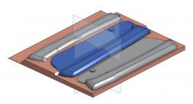
08_thicken_base_plate.jpg

... and the shape of the saws subtracted from the base plate. A little bit of tidying up of the shape resulted in this:
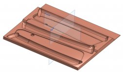
09_subtract.jpg

Another simple sketch was made on the front face of the model:
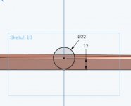
10_sketch_for_finger_hole.jpg

That got extruded as a cut into the front of the model and then the various edges softened using fillets.
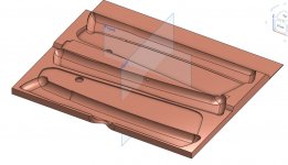
11_finger_hole_extruded_and_filleted.jpg

That cut-out gives a bit of clearance behind the finger pull hole.

Finally, a couple of surfaces were created, each bisecting the model:
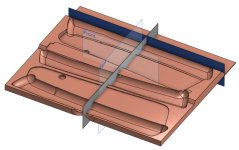
12_splitting_surfaces.jpg

These were used to split the model into four pieces, each small enough to fit on the bed of the 3D printer.
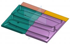
13_ready_to_print.jpg

I chose to split near the back as it means (a) that the saw body sections are in fewer pieces and (b) if I figure out something else that I want to put in that 40 mm wide section at the back of the drawer, I only have to reprint the 40 mm wide section and not half the drawer.

A little while later and the drawer is ready for use:
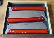
14_finished_drawer.jpg
 
Back
Top