
-
Hi all and welcome to TheWoodHaven2 brought into the 21st Century, kicking and screaming! We all have Alasdair to thank for the vast bulk of the heavy lifting to get us here, no more so than me because he's taken away a huge burden of responsibility from my shoulders and brought us to this new shiny home, with all your previous content (hopefully) still intact! Please peruse and feed back. There is still plenty to do, like changing the colour scheme, adding the banner graphic, tweaking the odd setting here and there so I have added a new thread in the 'Technical Issues, Bugs and Feature Requests' forum for you to add any issues you find, any missing settings or just anything you'd like to see added/removed from the feature set that Xenforo offers. We will get to everything over the coming weeks so please be patient, but add anything at all to the thread I mention above and we promise to get to them over the next few days/weeks/months. In the meantime, please enjoy!
You are using an out of date browser. It may not display this or other websites correctly.
You should upgrade or use an alternative browser.
You should upgrade or use an alternative browser.
Holiday Toolchest
- Thread starter Dr.Al
- Start date

Dr.Al
Old Oak
Malc2098":23fgh38s said:SSoCNCM
Gesundheit

Malc2098
Sequoia
Dr.Al":1469c9zs said:Malc2098":1469c9zs said:SSoCNCM
Gesundheit
:lol:

Dr.Al":fhckdm4y said:Andyp":fhckdm4y said:I like the idea of AndyT’s three fingered milled brass pull. Shouldn’t be difficult to make.
I think you underestimate how much more complicated it is to make a rounded rectangle (slot) with even wall thickness all round compared to making a cylinder. The milling operation would be complex and not a lot of fun really, especially having to do it 6 times for 6 drawers. There's then the extra accuracy required in getting the drilled holes (in the wood) for the slot ends perfectly aligned. I've done it for the locking knobs, but only because I couldn't think of a better way.
At the risk of disappointing the secret society, I'm afraid a milled slot thing isn't even making the shortlist!
Oh I knew how complicated it would be but was trying to get my membership ratified


Mike G
Petrified Pine
Al Peter Follansby is probably the best traditional chip-carver on Youtube, if you're looking for ideas. You'll soon see what I was talking about with striking straight down then taking out a chip horizontally being the fundamental of al low relief carving.
Dr.Al
Old Oak
Mike G":1qhejw6t said:Al Peter Follansby is probably the best traditional chip-carver on Youtube, if you're looking for ideas. You'll soon see what I was talking about with striking straight down then taking out a chip horizontally being the fundamental of al low relief carving.
Thanks Mike, I'll check out his stuff. I've also ordered a couple of books (one on chip carving and one on relief carving). I must admit I find it a bit frustrating that it a lot of stuff online goes by "choose your technique, then choose your pattern", whereas I'm trying to choose a pattern and then learn whatever technique is right for that pattern :?
The biggest problem, of course, is that I have virtually zero artistic ability so I've no idea where to start with coming up with a pattern. I've come pretty close to completely giving up on the idea, but perhaps the books and/or Mr Follansbee will help.
The one thought I did have was that if I set a recessed pull into the middle (left-to-right) of the front of the chest, it might be interesting to integrate that circle into the design somehow. However, that might just be making things even more complicated than they need to be :lol:
Dr.Al":qn5m44u5 said:However, that might just be making things even more complicated than they need to be :lol:
The society's work goes on.
Cabinetman
Sequoia
- Joined
- Oct 11, 2020
- Messages
- 5,837
- Reaction score
- 1,478
- Location
- Lincolnshire Wolds + Massachusetts
- Name
- Ian
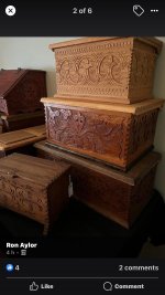
Stumbled over this and thought of your tool chest Al. It’s not my cup of tea - at all! But it might give you some ideas.
Dr.Al
Old Oak
Thanks Ian. That's a bit more ornate than I'd like: I'm after something quite simple I think - just something to break up the big wall of rather plain wood.
The two books arrived. The cover photo of the relief carving one was quite misleading from my point of view: it showed some simple patterns (from a practice piece near the start of the book). With the exception of the technique practice piece, all the actual patterns in the book were for more pictorial stuff (of this style), which isn't my cup of tea at all.
The chip carving book seems quite good though, so I'll read that one in more detail and see if anything inspires me.
I haven't watched any of Peter Follansbee's videos yet. I spend most of my day in front of a computer at work, so I'm not always that enthusiastic about watching youtube and I'd much rather read a book
The two books arrived. The cover photo of the relief carving one was quite misleading from my point of view: it showed some simple patterns (from a practice piece near the start of the book). With the exception of the technique practice piece, all the actual patterns in the book were for more pictorial stuff (of this style), which isn't my cup of tea at all.
The chip carving book seems quite good though, so I'll read that one in more detail and see if anything inspires me.
I haven't watched any of Peter Follansbee's videos yet. I spend most of my day in front of a computer at work, so I'm not always that enthusiastic about watching youtube and I'd much rather read a book
Dr.Al
Old Oak
While the carving and drawer pull pondering continues, I wanted to have a go at the drawer numbering. Experience tells me that this is going to take quite a few attempts to get right :lol:
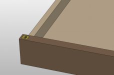
The plan is to have a small brass insert, about 10 mm square with a number engraved or etched into the surface. Something like this:
There are three approaches that I see as viable for this:
Engraving is a messy process and doesn't give the prettiest result, so I think I'd prefer to go with etching. I've never tried photolithography (although I think I've got most of the stuff that would be needed and I'd like to give it a try), so I thought I'd start with the toner transfer option.
I've tried toner transfer etching several times before and found it to be a rather hit-and-miss process, but I've got some "press-n-peel" paper left over from the last time I tried, so I figured I might as well give it a shot. For this process. it's necessary to print a mirrored and inverted version of the image onto the transfer paper using a laser printer. I don't have a laser printer, but my work does
As I knew it was going to take multiple attempts to get it right, I filled the page with numbers (all printed in Arial Rounded MT Bold in case anyone cares):
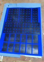
The faint border is 10 mm square and is intended to give me a mark to file down to after the parts have been cut out of the brass stock.
I went through (at least part of) this process several times; the photos below were from attempt number 5 which was the best of the 5 attempts I've made so far; as I said: it's a bit hit & miss.
The first step is to cut a bit of thin brass sheet to about the right size and give it a very, very thorough clean, first with 400 grit wet & dry paper under a running tap, then with acetone.
A section out of the press-n-peel paper is fixed it in place with some masking tape (with the toner side down):
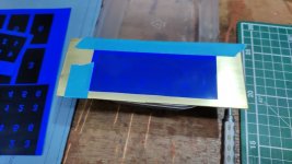
A piece of paper is then placed on top (to stop the iron sticking to the paper) and an iron is used to heat everything up while pressing the paper down onto the thin brass sheet (a better option is apparently to use a laminator rather than an iron, but I don't have one). The idea is that the toner detaches itself from the press-n-peel paper and sticks to the brass instead.
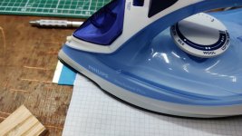
After ironing for a bit, it's clear that the colour has changed a bit, indicating that the toner has melted and detached from the film:
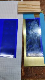
This is the first moment of truth with this process: you then peel the press-n-peel paper away to see what it looks like:
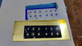
Not great. That's far, far better than any of the previous attempts, but still not great.
Wherever possible, the blemishes can be filled in with marker pens (paint might be better, but marker pens work and they're quicker):
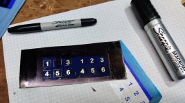
I rescored the borders (not very accurately ), which hadn't come out very well and then the final preparation stage was to chop the brass piece in half and superglue on some bits of plastic.
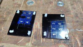
The plastic bits I used were just some cable pins with the pin removed. During etching, the to-be-etched face points down (so that etched material falls away) and the cable pins are just there to lift the face off the bottom of the tray in which the etching is done.
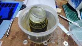
While all of that was happening, I put my (10+ year old) jar of ferric chloride in a plastic tub and poured boiling water into the tub to warm the ferric chloride up a bit. 70°C is a good target, although I didn't measure the temperature.
I could then put the two brass pieces number side down into a takeaway tray, pour the ferric chloride over the top and then fill the outer container with boiling water to help keep things warm.
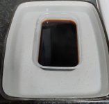
A scrappy bit of plywood was chucked over the top to help contain the heat and then it was left for 30 minutes.
Once the timer went off, I pulled the parts out of the ferric chloride and gave them a thorough clean under the tap and then removed the toner with acetone. The results were again not great:
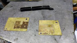
It looks like the toner hadn't adhered very well on one of the halves and hadn't protected the brass from the toner anywhere near as well as the marker pen had.
Nevertheless, I figured I might as well carry on to keep practising the process as much as possible. That broken stick in the top of the previous image is an engraver's black shellac stick (can't remember the proper name for it, but it's basically shellac with a dark pigment). The brass bits got heated up and, once nice and toasty, the shellac stick got shoved into the face of the brass, whereupon it melted and glooped over everything:

It probably would have been better to heat the brass a bit more than I did so the shellac went more runny and didn't end up quite so thick, but that's why I'm practising!
Once the brass bits had cooled down thoroughly, I attacked it with some 600 grit wet & dry paper. Part way through:
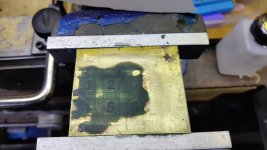
Nearly there:
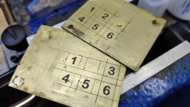
The last stage was to shove the brass bits in the kitchen oven at 180°C for a bit (probably not actually that hot as I took them out before the oven had got up to temperature). That remelts the shellac and gives a more glossy finish:
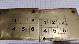
They're much better than my previous attempts, but there's definitely still room for improvement. I'm inclined to have a go at the photolithography process on the next attempt, although there's quite a lot of set-up to do and I'm sure that photolithography will take a few attempts as well. I'll also be using lots of old materials (e.g. the photosensitive film, which I bought about 5 years ago when I was last trying etching but still haven't got round to using). Hopefully the old materials won't have degraded and will still work okay.
The plan is to have a small brass insert, about 10 mm square with a number engraved or etched into the surface. Something like this:
There are three approaches that I see as viable for this:
- Engrave it with my home-made pantograph.
- Use a toner-transfer process and etch it.
- Use a photolithography process and etch it.
Engraving is a messy process and doesn't give the prettiest result, so I think I'd prefer to go with etching. I've never tried photolithography (although I think I've got most of the stuff that would be needed and I'd like to give it a try), so I thought I'd start with the toner transfer option.
I've tried toner transfer etching several times before and found it to be a rather hit-and-miss process, but I've got some "press-n-peel" paper left over from the last time I tried, so I figured I might as well give it a shot. For this process. it's necessary to print a mirrored and inverted version of the image onto the transfer paper using a laser printer. I don't have a laser printer, but my work does
As I knew it was going to take multiple attempts to get it right, I filled the page with numbers (all printed in Arial Rounded MT Bold in case anyone cares):
The faint border is 10 mm square and is intended to give me a mark to file down to after the parts have been cut out of the brass stock.
I went through (at least part of) this process several times; the photos below were from attempt number 5 which was the best of the 5 attempts I've made so far; as I said: it's a bit hit & miss.
The first step is to cut a bit of thin brass sheet to about the right size and give it a very, very thorough clean, first with 400 grit wet & dry paper under a running tap, then with acetone.
A section out of the press-n-peel paper is fixed it in place with some masking tape (with the toner side down):
A piece of paper is then placed on top (to stop the iron sticking to the paper) and an iron is used to heat everything up while pressing the paper down onto the thin brass sheet (a better option is apparently to use a laminator rather than an iron, but I don't have one). The idea is that the toner detaches itself from the press-n-peel paper and sticks to the brass instead.
After ironing for a bit, it's clear that the colour has changed a bit, indicating that the toner has melted and detached from the film:
This is the first moment of truth with this process: you then peel the press-n-peel paper away to see what it looks like:
Not great. That's far, far better than any of the previous attempts, but still not great.
Wherever possible, the blemishes can be filled in with marker pens (paint might be better, but marker pens work and they're quicker):
I rescored the borders (not very accurately
), which hadn't come out very well and then the final preparation stage was to chop the brass piece in half and superglue on some bits of plastic.The plastic bits I used were just some cable pins with the pin removed. During etching, the to-be-etched face points down (so that etched material falls away) and the cable pins are just there to lift the face off the bottom of the tray in which the etching is done.
While all of that was happening, I put my (10+ year old) jar of ferric chloride in a plastic tub and poured boiling water into the tub to warm the ferric chloride up a bit. 70°C is a good target, although I didn't measure the temperature.
I could then put the two brass pieces number side down into a takeaway tray, pour the ferric chloride over the top and then fill the outer container with boiling water to help keep things warm.
A scrappy bit of plywood was chucked over the top to help contain the heat and then it was left for 30 minutes.
Once the timer went off, I pulled the parts out of the ferric chloride and gave them a thorough clean under the tap and then removed the toner with acetone. The results were again not great:
It looks like the toner hadn't adhered very well on one of the halves and hadn't protected the brass from the toner anywhere near as well as the marker pen had.
Nevertheless, I figured I might as well carry on to keep practising the process as much as possible. That broken stick in the top of the previous image is an engraver's black shellac stick (can't remember the proper name for it, but it's basically shellac with a dark pigment). The brass bits got heated up and, once nice and toasty, the shellac stick got shoved into the face of the brass, whereupon it melted and glooped over everything:
It probably would have been better to heat the brass a bit more than I did so the shellac went more runny and didn't end up quite so thick, but that's why I'm practising!
Once the brass bits had cooled down thoroughly, I attacked it with some 600 grit wet & dry paper. Part way through:
Nearly there:
The last stage was to shove the brass bits in the kitchen oven at 180°C for a bit (probably not actually that hot as I took them out before the oven had got up to temperature). That remelts the shellac and gives a more glossy finish:
They're much better than my previous attempts, but there's definitely still room for improvement. I'm inclined to have a go at the photolithography process on the next attempt, although there's quite a lot of set-up to do and I'm sure that photolithography will take a few attempts as well. I'll also be using lots of old materials (e.g. the photosensitive film, which I bought about 5 years ago when I was last trying etching but still haven't got round to using). Hopefully the old materials won't have degraded and will still work okay.
Dr.Al
Old Oak
Malc2098":1y9o48w4 said:Wow!
Blimey Malc, have you been learning new vocabulary? :lol:
Malc2098
Sequoia
Dr.Al":1o8cjcek said:Malc2098":1o8cjcek said:Wow!
Blimey Malc, have you been learning new vocabulary? :lol:
:lol: :lol: :lol:
There really is nothing left for the secret society to suggest.
NickM
Old Oak
Great to see something new (to me) being described so thoroughly.
They'll look great, but just to throw another numbering option into the mix: you could carve Roman numerals straight into the wood. Being straight lines, the Roman numerals should be quite easy to carve (even if they're small). The Romans were clever like that...
They'll look great, but just to throw another numbering option into the mix: you could carve Roman numerals straight into the wood. Being straight lines, the Roman numerals should be quite easy to carve (even if they're small). The Romans were clever like that...
Dr.Al
Old Oak
NickM":2z966ogy said:Great to see something new (to me) being described so thoroughly.
They'll look great, but just to throw another numbering option into the mix: you could carve Roman numerals straight into the wood. Being straight lines, the Roman numerals should be quite easy to carve (even if they're small). The Romans were clever like that...
Thanks Nick. I think AndyP already suggested that and yes, it's definitely another option.
I know I've said this a few times, but part of this project is for me to learn and practice as many different skills/techniques as possible. I've done some simple etching before, but only twice and I definitely haven't mastered the technique, so it's nice to have an excuse to experiment and figure out how to do it well. I also love the look of brass against walnut
In case anyone cares, my previous attempts at etching follow...
The first one was a simple disc of aluminium bronze. A friend of Carolyn's called Hayley (who lived in Finland) was going to run her first half-marathon in her native South Africa. Unfortunately, do to various unforeseen problems, it became impossible for her to travel to South Africa for the race that she'd signed up for, so she decided to run a half-marathon on her own in Finland at the same time as the one was happening in South Africa. As she was doing the run independently and the finish line would just be a few friends and family standing around, we thought it would be nice for her kids to be able to hand over a medal when she finished, so I made this:
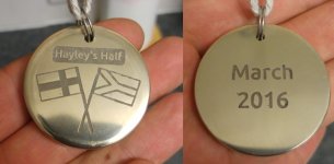
(It got a new lanyard before being handed over - the string was just what came to hand for the photo).
This was before I'd discovered engraver's black shellac & I honestly can't remember how I did the etching for that one: according to my email history it was made two years before I first discovered press-n-peel paper, so I must have come up with some other way to do toner transfer or similar.
The second was a gift for my father - a finger plate clamping tool, into which I set his initials on a brass plate. This was done with press-n-peel paper (again using an entire sheet and having quite a lot of attempts!) and the engraver's shellac.
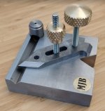
I do remember that the etching process for both of the above was quite fraught and took a few attempts, so it would be nice to get to the point that I can do it a bit more consistently when the need/desire arises.

Phil
Old Oak
Malc2098":1jfgnfgm said:Wow!
:text-goodpost:
Very interesting read.

One day when I have nothing to do I will try it.

When I retire ...................
Andyp":33k2twl1 said:There really is nothing left for the secret society to suggest.
Given that Dr Al himself now seems to be a member...
I'd have done roman numerals. I think someone said earlier that roman numerals only had straight lines. C and D don't. Although that would have to be a pretty damn big set of drawers, and is therefore a petty and pedantic quibble. And I expect it to be treated as such. I think some (but not all) of the runic numbering systems really are only straight lines. Another rabbit hole.
Tiresias":2epo8ogw said:Andyp":2epo8ogw said:There really is nothing left for the secret society to suggest.
Given that Dr Al himself now seems to be a member...
I'd have done roman numerals. I think someone said earlier that roman numerals only had straight lines. C and D don't.
I think I said 1-100 were straight lines which is incorrect. It would only need a 90 drawer cabinet before curves were needed.
Dr.Al
Old Oak
Exercises in photolithography. I haven't finished the photolithography versions yet, but I'm making progress, so I thought I'd write it up.
I bought some "inkjet transparency film" and printed out a pattern on my inkjet printer (as with the press-n-peel paper, the image is inverted, but unlike the press-n-peel, it isn't inverted for this process). It looked a bit pants to be honest (I possibly just need to tweak the printer settings a bit) so I decided to take some of the acetate into work and print the pattern on the laserjet - that came out looking much better.
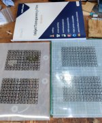
As you can see I also made the mistake of leaving the inkjet one lying ink side down on a bit of cardboard, which proceeded to stick to the ink!
Next up was to assemble the kit I needed, some of which is shown in this photo.
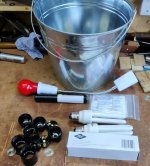
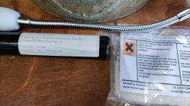
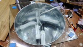
That includes a metal bucket (metal as it'll be more reflective than plastic), some UV light bulbs, some light fittings for E27 screw thread bulbs, a darkroom safe light (basically just a red bulb) and these two chemicals - photosensitive film and photoresist developer:
There were also a handful of more mundane tools like an iron, a cutting mat, a knife and ruler, some masking tape etc.
The lights were wired up to a plug and dumped in the bottom of the bucket and a (rather scratched, which probably isn't ideal) piece of glass placed on top:
The first part of the process is very similar to the press-n-peel process: trim the template to size and give the brass piece a very thorough clean: I used 600 grit wet & dry under a running tap and then cleaned the surface with acetone.

Once everything was ready, I then left it all for a few hours as I needed to wait until it got dark outside (I suppose there's one benefit of these ridiculously short evenings).
I didn't take many photos of the process from here for the simple reason that it's all done under dim red light and it really isn't very easy to see, let alone take any photos:
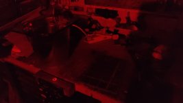
You'll just have to put up with a textual description (or go and watch #9 in Clickspring's Byzantine Sundial Calendar series, which is what I based the process on).
Once the light is off, it gets really hard to see what's going on. The first thing to do is get the photosensitive film out of the black tube and cut a bit off. The photosensitive film has two layers of protective cover. One gets removed immediately (with a bit of masking tape stuck on the corner to help lift it) and then the film gets laid on the brass plate and pressed firmly with a bit of paper towel.
The paper towel is rubbed around a lot to try to get rid of any air bubbles. If there are any major ones, the film can be lifted and then you can have another go. If you manage to crease the film, then you just have to cut another piece and try again. The brass has to be really, really clean and free of particles - I don't think I got it quite clean enough, but in my case I don't think it's a problem (as I'm making lots of spares so I only really need one of each number to work).
Once the film is smooth all over the brass, a piece of paper is put on top and then an iron (I used the wool setting on the successful attempts) is briefly but firmly pressed on the paper. This sticks the film firmly to the brass. You can check progress by removing the iron and trying to tug on the corner of the film. If it peels off easily, you need more iron time.
Once the film is firmly attached, I trimmed any excess off and then peeled away the other protective layer. The transparency is then placed on top with the printed side against the film (hence printing it mirrored).
The whole lot is then placed face down on the glass-covered bucket, then something heavy put on top to stop anything from shifting (I used a bit of wood and a smoothing plane!). I then put my lab coat over the top of the whole assembly (I don't know how dangerous UV bulbs are but I thought it better to err on the side of caution).
The power was then turned on and I left it for 1 minute and 40 seconds before turning the power off again.
At that point, you need some of the photoresist developer mixed up. I intended to mix up a quarter of the pack, but slipped on the scales and mixed up a half of the pack instead. The stuff I've got wants 25 g per litre in room temperature water.
The brass piece goes into the developer for about 30 seconds, brushing with a soft brush all over the surface until the unexposed film has all gone. It's then rinsed in tap water (and the light can come back on!)
That description covers what I did on the third attempt. The first attempt looked like this:
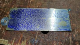
On my first attempt I'd assumed that it needed a similar amount of ironing to the press-n-peel paper. It really doesn't: that much heat just melts everything!
This was my second attempt:
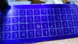
That was before I re-read the notes I'd made while watching the Clickspring video - I hadn't used the soft brush while it was in the developer. Going back and having another go in the developer resulted in it being over developed.
This was the next attempt:
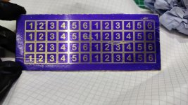
I was happy with that. There are some definite blemishes where the film hadn't stuck properly, but given this is the first day of photolithography for me, I thought it was worth carrying on.
Next job was sharpie marking some of the blemishes (I really should have done this with paint, but I was being impatient) and gluing on the plastic clips again.
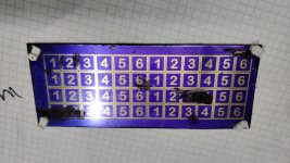
It then went in the warm ferric chloride bath for 25 minutes:
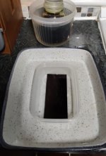
Finally, it came out, was rinsed with water and then dunked in acetone to remove the film completely:
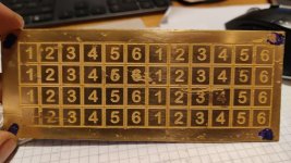
I think there should be enough good squares in there to do the job, but we'll see what it looks like once I've added the black shellac and cleaned it all up (that's a job for tomorrow).
Given that this is the first time I've tried photolithography, I'm really pleased with the result. It's a much, much nicer process to do than the press-n-peel stuff. Ironing the film on is quick and you can check progress and carry on if it hasn't worked (rather than starting again like the press-n-peel film). The printed transparency is reusable rather than sacrificial like the press-n-peel film. The UV cure bit is quite quick and once it's come out of the developer you can easily see whether the process has worked. If it looks a bit shabby, you just wash the film off with acetone and have another go, so you don't waste the brass piece.
It's a bit awkward working under the dim red light (although it probably would have been better if the light wasn't behind me so I was also working in shadow ), but overall it's a much better option I think. With hindsight it would have been better to space the numbers out a bit more: I've got some fairly narrow lines to cut down, but I think it'll be okay if I'm careful. I'll worry about that after blackening the numbers tomorrow.
I bought some "inkjet transparency film" and printed out a pattern on my inkjet printer (as with the press-n-peel paper, the image is inverted, but unlike the press-n-peel, it isn't inverted for this process). It looked a bit pants to be honest (I possibly just need to tweak the printer settings a bit) so I decided to take some of the acetate into work and print the pattern on the laserjet - that came out looking much better.
As you can see I also made the mistake of leaving the inkjet one lying ink side down on a bit of cardboard, which proceeded to stick to the ink!
Next up was to assemble the kit I needed, some of which is shown in this photo.
That includes a metal bucket (metal as it'll be more reflective than plastic), some UV light bulbs, some light fittings for E27 screw thread bulbs, a darkroom safe light (basically just a red bulb) and these two chemicals - photosensitive film and photoresist developer:
There were also a handful of more mundane tools like an iron, a cutting mat, a knife and ruler, some masking tape etc.
The lights were wired up to a plug and dumped in the bottom of the bucket and a (rather scratched, which probably isn't ideal) piece of glass placed on top:
The first part of the process is very similar to the press-n-peel process: trim the template to size and give the brass piece a very thorough clean: I used 600 grit wet & dry under a running tap and then cleaned the surface with acetone.
Once everything was ready, I then left it all for a few hours as I needed to wait until it got dark outside (I suppose there's one benefit of these ridiculously short evenings).
I didn't take many photos of the process from here for the simple reason that it's all done under dim red light and it really isn't very easy to see, let alone take any photos:
You'll just have to put up with a textual description (or go and watch #9 in Clickspring's Byzantine Sundial Calendar series, which is what I based the process on).
Once the light is off, it gets really hard to see what's going on. The first thing to do is get the photosensitive film out of the black tube and cut a bit off. The photosensitive film has two layers of protective cover. One gets removed immediately (with a bit of masking tape stuck on the corner to help lift it) and then the film gets laid on the brass plate and pressed firmly with a bit of paper towel.
The paper towel is rubbed around a lot to try to get rid of any air bubbles. If there are any major ones, the film can be lifted and then you can have another go. If you manage to crease the film, then you just have to cut another piece and try again. The brass has to be really, really clean and free of particles - I don't think I got it quite clean enough, but in my case I don't think it's a problem (as I'm making lots of spares so I only really need one of each number to work).
Once the film is smooth all over the brass, a piece of paper is put on top and then an iron (I used the wool setting on the successful attempts) is briefly but firmly pressed on the paper. This sticks the film firmly to the brass. You can check progress by removing the iron and trying to tug on the corner of the film. If it peels off easily, you need more iron time.
Once the film is firmly attached, I trimmed any excess off and then peeled away the other protective layer. The transparency is then placed on top with the printed side against the film (hence printing it mirrored).
The whole lot is then placed face down on the glass-covered bucket, then something heavy put on top to stop anything from shifting (I used a bit of wood and a smoothing plane!). I then put my lab coat over the top of the whole assembly (I don't know how dangerous UV bulbs are but I thought it better to err on the side of caution).
The power was then turned on and I left it for 1 minute and 40 seconds before turning the power off again.
At that point, you need some of the photoresist developer mixed up. I intended to mix up a quarter of the pack, but slipped on the scales and mixed up a half of the pack instead. The stuff I've got wants 25 g per litre in room temperature water.
The brass piece goes into the developer for about 30 seconds, brushing with a soft brush all over the surface until the unexposed film has all gone. It's then rinsed in tap water (and the light can come back on!)
That description covers what I did on the third attempt. The first attempt looked like this:
On my first attempt I'd assumed that it needed a similar amount of ironing to the press-n-peel paper. It really doesn't: that much heat just melts everything!
This was my second attempt:
That was before I re-read the notes I'd made while watching the Clickspring video - I hadn't used the soft brush while it was in the developer. Going back and having another go in the developer resulted in it being over developed.
This was the next attempt:
I was happy with that. There are some definite blemishes where the film hadn't stuck properly, but given this is the first day of photolithography for me, I thought it was worth carrying on.
Next job was sharpie marking some of the blemishes (I really should have done this with paint, but I was being impatient) and gluing on the plastic clips again.
It then went in the warm ferric chloride bath for 25 minutes:
Finally, it came out, was rinsed with water and then dunked in acetone to remove the film completely:
I think there should be enough good squares in there to do the job, but we'll see what it looks like once I've added the black shellac and cleaned it all up (that's a job for tomorrow).
Given that this is the first time I've tried photolithography, I'm really pleased with the result. It's a much, much nicer process to do than the press-n-peel stuff. Ironing the film on is quick and you can check progress and carry on if it hasn't worked (rather than starting again like the press-n-peel film). The printed transparency is reusable rather than sacrificial like the press-n-peel film. The UV cure bit is quite quick and once it's come out of the developer you can easily see whether the process has worked. If it looks a bit shabby, you just wash the film off with acetone and have another go, so you don't waste the brass piece.
It's a bit awkward working under the dim red light (although it probably would have been better if the light wasn't behind me so I was also working in shadow
), but overall it's a much better option I think. With hindsight it would have been better to space the numbers out a bit more: I've got some fairly narrow lines to cut down, but I think it'll be okay if I'm careful. I'll worry about that after blackening the numbers tomorrow.
Dr.Al
Old Oak
First job for the morning was a tidy up of all the photolithography stuff. Then I heated the brass plate up with a blow torch and melted some shellac wax into all over it as before. 600 grit wet & dry paper (lubricated with WD40) was used to clean up the face:
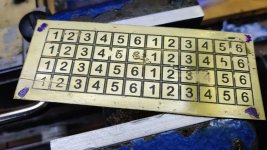
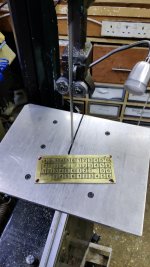
I put my home-made vertical table in the horizontal bandsaw and chopped a few of the bits up.
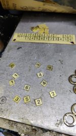
I kept going until I had a couple of promising examples of each number, then left the rest as spares.
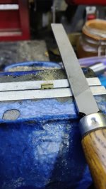
Each piece was then held in the bench vice (which has home-made aluminium soft jaws) and filed at a slight angle (narrowing towards the back) until the border line just disappeared.
Each piece then got a few strokes face down on some 1200 grit wet & dry paper to finish them off.
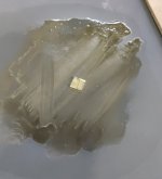
Finally, they went in the kitchen oven at 180°C for a bit to smooth out the wax. It didn't go as glossy this time, but I'm still happy with how it looks.
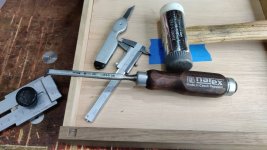
Finally, I chopped out some mortices in the top of each drawer with an 8 mm chisel...
... and glued the brass number plates in with some superglue.
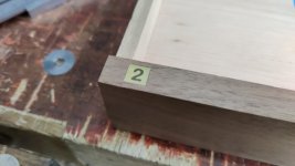
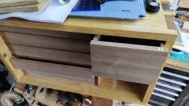
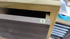
With that done, I could finally take off the masking tape (with drawer numbers written on) that has been on the drawers for the last 6 months
I put my home-made vertical table in the horizontal bandsaw and chopped a few of the bits up.
I kept going until I had a couple of promising examples of each number, then left the rest as spares.
Each piece was then held in the bench vice (which has home-made aluminium soft jaws) and filed at a slight angle (narrowing towards the back) until the border line just disappeared.
Each piece then got a few strokes face down on some 1200 grit wet & dry paper to finish them off.
Finally, they went in the kitchen oven at 180°C for a bit to smooth out the wax. It didn't go as glossy this time, but I'm still happy with how it looks.
Finally, I chopped out some mortices in the top of each drawer with an 8 mm chisel...
... and glued the brass number plates in with some superglue.
With that done, I could finally take off the masking tape (with drawer numbers written on) that has been on the drawers for the last 6 months
Dr.Al
Old Oak
Thanks Malc, your descent into verbosity is appreciated
Right, you might want to sit down before reading on...
... I've made a decision about the drawer pulls!
When I did the test piece, I didn't document the process of making the brass bits. Since I needed to make a load more of them, I thought I'd write it up here.
I started with a bit of 32-ish mm brass bar (which, as I've mentioned before, I got rather a lot of for free a few years ago). The first job was to face the end of the bar, with the tool inverted and the lathe running backwards so it would fire the brass bits downwards instead of up into my face:
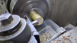
I then turned the two outer diameters (25 mm for about 20 mm length, then 22 mm for 13 mm length), making note of the cross-feed dial settings on the first one so I could just work to the cross-slide settings on the later ones.
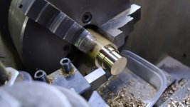
I gave the outside corners a quick touch with a smooth file, then used an 8 mm spot drill to start a central hole:
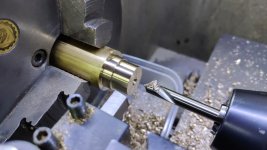
I then drilled 10 mm and then 13 mm:
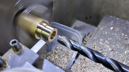
Then went in with an 18 mm end mill to a depth of 16 mm or so:
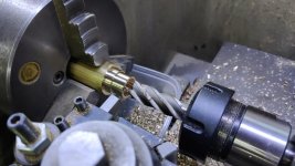
A large countersink was used to turn a circa 1 mm chamfer on the inside rim:
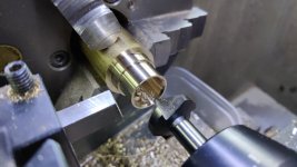
I could have parted it off there, but given that it needed to go back in the lathe to have the other end worked on, I just chopped it off with the bandsaw:
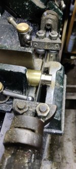
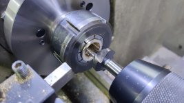
I did the same operations to all the other ones, then swapped the three-jaw chuck for a collet chuck. That was used to finish the other end: facing to length and chamfering with the countersink bit again:
The first stage in fitting the inserts to the drawers was to put some masking tape on the face of the drawer and mark the centre:
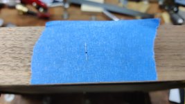
The masking tape is partly there to make the marks easier to see, but mainly there to protect the face from being marked by the depth stop.
Speaking of the depth stop, I made a new one, seen next to the old one here:
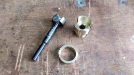
The new one has two advantages: firstly it's a lot more robust and less likely to move. The second advantage is the cut-outs in the sides, more clearly visible here:
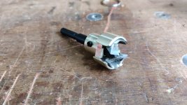
They give the waste wood an escape route: With the previous depth stop I found I was frequently having to remove the Forstner bit and clear the waste away manually. The red colour in the image above is just a reflection of something or other that was lying on my bench.
The 25 mm Forstner bit was used with an egg-whisk drill and the depth stop to drill the first bit of the hole:
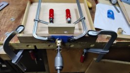
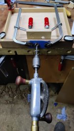
Then a 22 mm Forstner bit went the rest of the way through (with a small offcut of plywood to prevent break-out on exit):
Then it was just a case of fitting them. They're a tight enough fit that they needed a bit of persuasion (with an F-clamp) to slide in, so I didn't bother gluing them in place. I don't think they'll go anywhere.
That's all the drawer pulls done, phew!
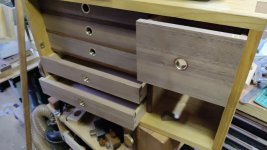
I'll take a better photo in daylight tomorrow. I've no idea why the right-hand drawer insert looks a purple colour in the photo: it looks like all the others in reality.
If I did this exercise again, I'd definitely drill the holes before assembling the drawers. I'd put it off partly because I was expecting to just stick something simple on the outside and partly because I was rushing to have the drawers ready for the June holiday in France. Drilling the holes would have been much easier if I could have used the pillar drill. To be honest, if I did the exercise again, I'd used the powered pillar drill - drilling isn't noisy or dusty so doesn't fit into quite the same category of power tools as sanders and table saws etc, so I don't have quite the same aversion to it (even Paul Sellers uses a cordless power drill!). However, I'd told myself I'd use hand tools for woodwork wherever possible, so I wanted to prove to myself that I could do it.
That's the drawers basically done (ignoring inserts for holding tools in place, which I've pretty much decided I'll just 3D print). They still need oiling. What's the opinion of those on here regarding drawer oiling. I've seen lots of ̶a̶r̶g̶u̶m̶e̶n̶t̶s̶ discussions on-line about whether to:
I can see the argument for not oiling the inside if you're going to keep clothes in the drawer, but that doesn't apply here. I'd be interested to know any opinions here, although I'm probably leaning towards the oil everything option (or possibly oil everything except the base).
Right, you might want to sit down before reading on...
... I've made a decision about the drawer pulls!
When I did the test piece, I didn't document the process of making the brass bits. Since I needed to make a load more of them, I thought I'd write it up here.
I started with a bit of 32-ish mm brass bar (which, as I've mentioned before, I got rather a lot of for free a few years ago). The first job was to face the end of the bar, with the tool inverted and the lathe running backwards so it would fire the brass bits downwards instead of up into my face:
I then turned the two outer diameters (25 mm for about 20 mm length, then 22 mm for 13 mm length), making note of the cross-feed dial settings on the first one so I could just work to the cross-slide settings on the later ones.
I gave the outside corners a quick touch with a smooth file, then used an 8 mm spot drill to start a central hole:
I then drilled 10 mm and then 13 mm:
Then went in with an 18 mm end mill to a depth of 16 mm or so:
A large countersink was used to turn a circa 1 mm chamfer on the inside rim:
I could have parted it off there, but given that it needed to go back in the lathe to have the other end worked on, I just chopped it off with the bandsaw:
I did the same operations to all the other ones, then swapped the three-jaw chuck for a collet chuck. That was used to finish the other end: facing to length and chamfering with the countersink bit again:
The first stage in fitting the inserts to the drawers was to put some masking tape on the face of the drawer and mark the centre:
The masking tape is partly there to make the marks easier to see, but mainly there to protect the face from being marked by the depth stop.
Speaking of the depth stop, I made a new one, seen next to the old one here:
The new one has two advantages: firstly it's a lot more robust and less likely to move. The second advantage is the cut-outs in the sides, more clearly visible here:
They give the waste wood an escape route: With the previous depth stop I found I was frequently having to remove the Forstner bit and clear the waste away manually. The red colour in the image above is just a reflection of something or other that was lying on my bench.
The 25 mm Forstner bit was used with an egg-whisk drill and the depth stop to drill the first bit of the hole:
Then a 22 mm Forstner bit went the rest of the way through (with a small offcut of plywood to prevent break-out on exit):
Then it was just a case of fitting them. They're a tight enough fit that they needed a bit of persuasion (with an F-clamp) to slide in, so I didn't bother gluing them in place. I don't think they'll go anywhere.
That's all the drawer pulls done, phew!
I'll take a better photo in daylight tomorrow. I've no idea why the right-hand drawer insert looks a purple colour in the photo: it looks like all the others in reality.
If I did this exercise again, I'd definitely drill the holes before assembling the drawers. I'd put it off partly because I was expecting to just stick something simple on the outside and partly because I was rushing to have the drawers ready for the June holiday in France. Drilling the holes would have been much easier if I could have used the pillar drill. To be honest, if I did the exercise again, I'd used the powered pillar drill - drilling isn't noisy or dusty so doesn't fit into quite the same category of power tools as sanders and table saws etc, so I don't have quite the same aversion to it (even Paul Sellers uses a cordless power drill!). However, I'd told myself I'd use hand tools for woodwork wherever possible, so I wanted to prove to myself that I could do it.
That's the drawers basically done (ignoring inserts for holding tools in place, which I've pretty much decided I'll just 3D print). They still need oiling. What's the opinion of those on here regarding drawer oiling. I've seen lots of ̶a̶r̶g̶u̶m̶e̶n̶t̶s̶ discussions on-line about whether to:
- Just oil the outside and top face of the front
- Oil the above, plus the outside face of the sides
- Oil everything except the base, inside & out
- Oil everything, inside & out
- Variations on the above
I can see the argument for not oiling the inside if you're going to keep clothes in the drawer, but that doesn't apply here. I'd be interested to know any opinions here, although I'm probably leaning towards the oil everything option (or possibly oil everything except the base).
Fascinating and so glad you numbered drawer #6. Could have been a disaster had you tried to put that one in the wrong place.

I'm a bit disappointed we didn't get a chance to have two or three pages debating whether the drawers should be numbered top to bottom or bottom to top, and whether to start at 1 or zero!
Seriously though, I think the need for advice disappeared long ago. But if you still want opinions... I think it's normal for furniture making to just oil the drawer fronts, on the outside face, top edge and ends (including the dovetails but not the rest of the sides).
But this isn't furniture, it's a very smart toolchest. I expect you will want to keep the insides of the drawers clean and unstained by dirt. So oiling all over makes sense. Obviously, you'll need to leave them all indoors in the warm and dry for as long as you can bear - at least a week at this time of year - to be sure that nothing will stick.
Seriously though, I think the need for advice disappeared long ago. But if you still want opinions... I think it's normal for furniture making to just oil the drawer fronts, on the outside face, top edge and ends (including the dovetails but not the rest of the sides).
But this isn't furniture, it's a very smart toolchest. I expect you will want to keep the insides of the drawers clean and unstained by dirt. So oiling all over makes sense. Obviously, you'll need to leave them all indoors in the warm and dry for as long as you can bear - at least a week at this time of year - to be sure that nothing will stick.
Dr.Al
Old Oak
AndyT":3q2r9moe said:I'm a bit disappointed we didn't get a chance to have two or three pages debating whether the drawers should be numbered top to bottom or bottom to top, and whether to start at 1 or zero!
Seriously though, I think the need for advice disappeared long ago. But if you still want opinions... I think it's normal for furniture making to just oil the drawer fronts, on the outside face, top edge and ends (including the dovetails but not the rest of the sides).
But this isn't furniture, it's a very smart toolchest. I expect you will want to keep the insides of the drawers clean and unstained by dirt. So oiling all over makes sense. Obviously, you'll need to leave them all indoors in the warm and dry for as long as you can bear - at least a week at this time of year - to be sure that nothing will stick.
Thanks Andy, that's really useful.
Dr.Al
Old Oak
A few little odd jobs done today. Firstly, do you remember the blind pull I made as a trial for the drawers? If not, go back and read this earlier post! It's very much like the drawer pulls, except the hole doesn't go all the way through and there's a "lip" on the inside at the front, so it gives the finger something to pull on.
It's not going to be used for the drawers now, but the brass bit can still be useful: for pulling the front out after unlocking the knobs.
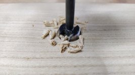
For this one, I used the hand-crank pillar drill. I started with a 25 mm Forstner bit:
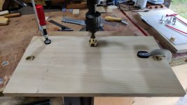
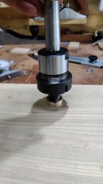
Then finished with a 22 mm Forstner bit (with the limit of travel of the pillar drill set such that the tip of the Forstner bit stayed about 1 mm from the far side of the shooting board):
That gave me a 13 mm deep hole; any deeper would have resulted in the tip of the Forstner bit coming out the other side. I needed a 15 mm deep hole. To deal with the difference, I dug out a 21 mm slot drill, put it in a collet chuck and turned it by hand to deepen the central bit of the hole (the brass thing in the picture is just something I turned out of a brass offcut to keep the slot drill central in the hole).
Once that was down to depth, I tidied up the bottom corners with a gouge.
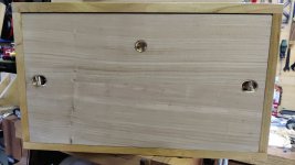
It could then be pressed into place (again without glue as it was a tight fit):
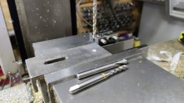
Another little job I did was on the planing stops. I used the milling machine to spot drill, drill 4.2 mm and tap M5: one hole in each planing stop.
I then turned some extremely simple little brass bits (for scale, the head is 9 mm diameter and 6 mm long, the thread is M5 and 4.5 mm long):
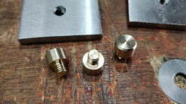
The brass bits go in the threaded holes and just provide something to push up & down on when moving the planing stop:
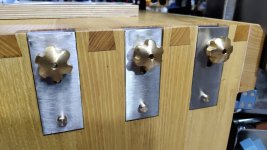
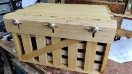
Another quick job: the 4 mm 303 stainless bar I'd ordered arrived in the week, so I fitted the cross-bars to the other two knobs:
I think the next job I'll do is give the chest top surface a quick skim with a smoothing plane and then oil the top and back of the chest, the drawers, the shooting board fences and the shooting board. I'd planned to leave oiling the shooting board until after carving a pattern, but I'm still no closer to having the faintest idea what sort of pattern to carve, so I think I'll just leave it for now. I can always come back to it at a later date: I don't see that a coat or two of oil will stop me from being able to carve into the surface.
There are still a few other jobs to do, but I'm definitely on the home straight. The ones that occur to me off the top of my head are:
There are a couple of other things on the "possibly, but probably not" list (including replacing the plywood drawer bases with hardwood ones), but they probably won't happen so I haven't included them here.
It's not going to be used for the drawers now, but the brass bit can still be useful: for pulling the front out after unlocking the knobs.
For this one, I used the hand-crank pillar drill. I started with a 25 mm Forstner bit:
Then finished with a 22 mm Forstner bit (with the limit of travel of the pillar drill set such that the tip of the Forstner bit stayed about 1 mm from the far side of the shooting board):
That gave me a 13 mm deep hole; any deeper would have resulted in the tip of the Forstner bit coming out the other side. I needed a 15 mm deep hole. To deal with the difference, I dug out a 21 mm slot drill, put it in a collet chuck and turned it by hand to deepen the central bit of the hole (the brass thing in the picture is just something I turned out of a brass offcut to keep the slot drill central in the hole).
Once that was down to depth, I tidied up the bottom corners with a gouge.
It could then be pressed into place (again without glue as it was a tight fit):
Another little job I did was on the planing stops. I used the milling machine to spot drill, drill 4.2 mm and tap M5: one hole in each planing stop.
I then turned some extremely simple little brass bits (for scale, the head is 9 mm diameter and 6 mm long, the thread is M5 and 4.5 mm long):
The brass bits go in the threaded holes and just provide something to push up & down on when moving the planing stop:
Another quick job: the 4 mm 303 stainless bar I'd ordered arrived in the week, so I fitted the cross-bars to the other two knobs:
I think the next job I'll do is give the chest top surface a quick skim with a smoothing plane and then oil the top and back of the chest, the drawers, the shooting board fences and the shooting board. I'd planned to leave oiling the shooting board until after carving a pattern, but I'm still no closer to having the faintest idea what sort of pattern to carve, so I think I'll just leave it for now. I can always come back to it at a later date: I don't see that a coat or two of oil will stop me from being able to carve into the surface.
There are still a few other jobs to do, but I'm definitely on the home straight. The ones that occur to me off the top of my head are:
- Remake the plane tote (I was never very happy with the two-bits-of-plywood-stuck-together plane tote, which was made in a bit of a rush ahead of the trip to France back in June; I've since dismantled it and will make a nicer one as one of the next jobs).
- Make something to stop the bottom drawer (and the plane tote) sliding forward. This will probably just be a "doe's foot" or two that make up the right thickness and will fit in the bottom of the chest before the front goes on.
- Drawer inserts - these will almost certainly be 3D printed and will take a long time to design. I'd been umming and ahing over whether to make them out of wood or 3D print them, but I think I've settled on 3D printing. It has the advantages of being lightweight and infinitely customisable; it has the disadvantage of taking quite a lot of work to get the shapes right to hold the various tools.
There are a couple of other things on the "possibly, but probably not" list (including replacing the plywood drawer bases with hardwood ones), but they probably won't happen so I haven't included them here.
Dr.Al
Old Oak
It's been a fairly busy weekend with lots of non-workshop stuff going on, but I have managed a couple of hours each day and in that time I've made a little progress.
Do you remember my old plane tote? Here it is:

It was made out of two bits of plywood stuck together and was a bit naff:

I'd made that in a bit of a rush before the trip to France in June and I've since been thinking it would be nice to make something a bit better. I've been pondering on different approaches and had pretty much settled on getting a thick bit of sweet chestnut and router planing out the shapes of the two planes. I could then put a small bit of walnut on the front.
However, I've since had a brainwave and found a better way. You might remember that there were two reasons I went with the plywood plane tote rather than making a drawer for the planes to sit in:
The first one of those is easy to sort out: there's no reason the drawer has to fill the available space - it can just be a narrow drawer of a similar depth to the ones on the left of the chest.
The brainwave I mentioned was that, if I mount the planes at an angle, the toe of the bevel-up smoothing plane can sit over the top of the drawer back. As I've decided to 3D print the inserts for the other drawers, I can also 3D print an insert for the plane drawer and that'll sort out getting it at the right angle.
The insert will look a bit like this:
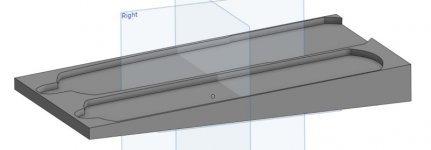
With that decided (and a 3D print done to prove the concept), I could get on with making a drawer. The drawer was made in much the same way as the previous drawers so I didn't bother taking photos of the process. Here it is:
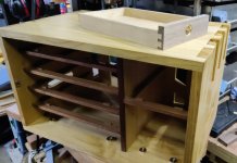
As you can see, I've also made eccentric drawer stops for this drawer, which I think is nice as it is in keeping with the left-hand bottom drawer.
Here it is in place:
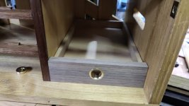
I'll make a brass "7" label for it in due course, again for consistency with the other drawers.
This is (sort-of) what it'll look like with the planes in place:
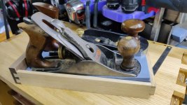
I say "sort-of" as I did that 3D print before deciding exactly what height the drawer would be, so the planes are lifted up further than they will be in the final version. I'll do the final print in black as well: this was just a case of using the filament that was already in the printer as it was just a test run.
Do you remember my old plane tote? Here it is:
It was made out of two bits of plywood stuck together and was a bit naff:
I'd made that in a bit of a rush before the trip to France in June and I've since been thinking it would be nice to make something a bit better. I've been pondering on different approaches and had pretty much settled on getting a thick bit of sweet chestnut and router planing out the shapes of the two planes. I could then put a small bit of walnut on the front.
However, I've since had a brainwave and found a better way. You might remember that there were two reasons I went with the plywood plane tote rather than making a drawer for the planes to sit in:
- Getting the planes out of a deep drawer would be a bit awkward, and...
- The bevel-up smoothing plane (which I bought after having made the body of the chest) is a little bit too long to fit in a drawer (assuming a 15 mm thick drawer front and an 8–10 mm thick back).
The first one of those is easy to sort out: there's no reason the drawer has to fill the available space - it can just be a narrow drawer of a similar depth to the ones on the left of the chest.
The brainwave I mentioned was that, if I mount the planes at an angle, the toe of the bevel-up smoothing plane can sit over the top of the drawer back. As I've decided to 3D print the inserts for the other drawers, I can also 3D print an insert for the plane drawer and that'll sort out getting it at the right angle.
The insert will look a bit like this:
With that decided (and a 3D print done to prove the concept), I could get on with making a drawer. The drawer was made in much the same way as the previous drawers so I didn't bother taking photos of the process. Here it is:
As you can see, I've also made eccentric drawer stops for this drawer, which I think is nice as it is in keeping with the left-hand bottom drawer.
Here it is in place:
I'll make a brass "7" label for it in due course, again for consistency with the other drawers.
This is (sort-of) what it'll look like with the planes in place:
I say "sort-of" as I did that 3D print before deciding exactly what height the drawer would be, so the planes are lifted up further than they will be in the final version. I'll do the final print in black as well: this was just a case of using the filament that was already in the printer as it was just a test run.
Dr.Al
Old Oak
Malc2098":2uqlqu02 said:Nice.
Thanks Malcolm.
Do those printed inserts allow the plane iron to be left un-retracted or are they soft enough not to cause a problem with the nicely honed edges?
Dr.Al
Old Oak
Andyp":dr0giz16 said:Do those printed inserts allow the plane iron to be left un-retracted or are they soft enough not to cause a problem with the nicely honed edges?
They're definitely soft enough, but I'll probably design a cut-out into the shape before doing the final print just to be on the safe side. I must admit it wasn't something I'd thought about, so thanks for mentioning it.

AJB Temple
Sequoia
- Joined
- Apr 15, 2019
- Messages
- 7,850
- Reaction score
- 1,313
Very nice work.
I presume that it must also have a regular place in the workshop, as time away on holiday must be limited unless you are a proper millennial who works from the beach hut mainly?
I have a plastic rectangular toolbox about 3ft by 10" by 10" that sometimes has in it what I consider to be essential hand tools when I go to fix things at family or friends houses (which I try hard to avoid). When it's tooled up I can hardly lift it. So I'm wondering what yours will weigh when ready to roll?
Is the plan to leave one of the kids and possibly Mrs Dr Al at home when you go on holiday so as to have enough space in the car for mobile w/s? How do you get away with this?
I presume that it must also have a regular place in the workshop, as time away on holiday must be limited unless you are a proper millennial who works from the beach hut mainly?
I have a plastic rectangular toolbox about 3ft by 10" by 10" that sometimes has in it what I consider to be essential hand tools when I go to fix things at family or friends houses (which I try hard to avoid). When it's tooled up I can hardly lift it. So I'm wondering what yours will weigh when ready to roll?
Is the plan to leave one of the kids and possibly Mrs Dr Al at home when you go on holiday so as to have enough space in the car for mobile w/s? How do you get away with this?
Dr.Al
Old Oak
AJB Temple":5dw4ytxw said:Very nice work.
Thanks Adrian, much appreciated.
AJB Temple":5dw4ytxw said:I presume that it must also have a regular place in the workshop, as time away on holiday must be limited unless you are a proper millennial who works from the beach hut mainly?
No, it's not going to get a home in the workshop for now. In fact I'll be quite pleased to get it out of the workshop as I'm seriously short of space and it gets in the way! While not being taken on holiday it'll live in the house somewhere (empty of tools): either in the dining room or on top of a wardrobe in the bedroom probably.
AJB Temple":5dw4ytxw said:I have a plastic rectangular toolbox about 3ft by 10" by 10" that sometimes has in it what I consider to be essential hand tools when I go to fix things at family or friends houses (which I try hard to avoid). When it's tooled up I can hardly lift it. So I'm wondering what yours will weigh when ready to roll?
When I took it to France for the "trial run" in June, I weighed it fully loaded, but I can't remember how much it was. About 30 kg maybe (but I might have remembered that completely wrong). It's definitely in the category of luggable rather than portable, but I can lift it for short distances without too much difficulty. The expectation is that it'll be carried from workshop to car (which isn't very far) and then from car to self-catering cottage (which hopefully won't be far) and will otherwise live a rather sedentary life, so the weight isn't too much of a problem.
AJB Temple":5dw4ytxw said:Is the plan to leave one of the kids and possibly Mrs Dr Al at home when you go on holiday so as to have enough space in the car for mobile w/s? How do you get away with this?
I have two key approaches that help with this:
- Have a big car (a Passat Estate)
- Don't have kids
AJB Temple
Sequoia
- Joined
- Apr 15, 2019
- Messages
- 7,850
- Reaction score
- 1,313
Not having kids is a good strategem. Mine is gradually and surreptitiously moving my tools from my house to his. Children call this "borrowing". :lol:
Dr.Al
Old Oak
AJB Temple":3cwtoi0z said:Not having kids is a good strategem. Mine is gradually and surreptitiously moving my tools from my house to his. Children call this "borrowing". :lol:
:text-lol:
Dr.Al":1n98vwtf said:It's definitely in the category of luggable rather than portable, but I can lift it for short distances without too much difficulty. The expectation is that it'll be carried from workshop to car (which isn't very far) and then from car to self-catering cottage (which hopefully won't be far) and will otherwise live a rather sedentary life, so the weight isn't too much of a problem.
Of course, you could do what a lot of my friends do and send your luggage on beforehand.
But then, obviously, you’d need a protective case to put your work chest in. Possibly something with brass bound corners and lined with padded leather. Campaign furniture sort of thing. Another box to make.
The secret society thrives…
To be fair, very nice work. But it’s the route one takes really, isn’t it? 'I took the one less travelled by, and that has made all the difference'.
AJB is Adrian BTW but I do agree with his comment.
Have you considered a small caravan to tow behind that Passat. With a small geni you could then take the lathe on holiday too. And the 3D printer :shock:
Have you considered a small caravan to tow behind that Passat. With a small geni you could then take the lathe on holiday too.
And the 3D printer :shock: