• Hi all and welcome to TheWoodHaven2 brought into the 21st Century, kicking and screaming! We all have Alasdair to thank for the vast bulk of the heavy lifting to get us here, no more so than me because he's taken away a huge burden of responsibility from my shoulders and brought us to this new shiny home, with all your previous content (hopefully) still intact! Please peruse and feed back. There is still plenty to do, like changing the colour scheme, adding the banner graphic, tweaking the odd setting here and there so I have added a new thread in the 'Technical Issues, Bugs and Feature Requests' forum for you to add any issues you find, any missing settings or just anything you'd like to see added/removed from the feature set that Xenforo offers. We will get to everything over the coming weeks so please be patient, but add anything at all to the thread I mention above and we promise to get to them over the next few days/weeks/months. In the meantime, please enjoy!

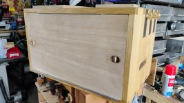
Holiday Toolchest

That’s looking good Dr Al.

If you are only going to use it on the shooting board, why not put a side handle on it. To save space, (and you seem to be pretty good at metal work) how about a folding polished steel handle – I just looked at some of the joints on my Leatherman, with a click lock, and I’m sure they could be adapted. It would look really natty.

Pointless, but natty, nonetheless.

Oh, and for the record the plane I posted earlier isn’t three part, it’s a single body. P19 of Haywards ‘Making Woodwork Tools’. I think it was the first plane I made. Oh, the delights of complete ignorance. I like kittens and knitting, but I’m going to have a go anyway…

I’ve done a two part one. Made the abutments (if that is what you call them) easier. I have a three part Krenovian on the go, and a big block of sycamore for a smoother for a 2 ¼ inch Mathieson cutter that, believe it or not, travelled all the way to Australia, where it was picked up on the roadside, by one of my brother’s staff (they have a habit in Sydney of putting reuseable stuff out on the pavement for passersby to take) , and returned, via my parents’ luggage allowance to me. Don’t count the airmiles.
 
Cabinetman":29v57fpp said:
Most impressive Al, but I think I would have rounded it’s rear end a bit before the finish went on myself.

I did wonder about it, but I figured it would be easy enough to round it later if I want it rounded. Finish can always be reapplied. It'll mostly be used on it's side & in that orientation it has a rounded rear end.

Tiresias":29v57fpp said:
That’s looking good Dr Al.
Thanks!

Tiresias":29v57fpp said:
If you are only going to use it on the shooting board, why not put a side handle on it. To save space, (and you seem to be pretty good at metal work) how about a folding polished steel handle – I just looked at some of the joints on my Leatherman, with a click lock, and I’m sure they could be adapted. It would look really natty.

A leatherman style joint sounds quite challenging, but I agree it could look natty (although "polished" isn't really in my vocabulary: I generally go for rough and ready :lol: ). I do like the folding side handle on my normal shooting plane, so it would be nice to have one on this. I think I might put that off for a later version!

Tiresias":29v57fpp said:
Oh, and for the record the plane I posted earlier isn’t three part, it’s a single body. P19 of Haywards ‘Making Woodwork Tools’. I think it was the first plane I made.

It looks very good for a first ever plane (and apologies for assuming it was a three-part!).

Tiresias":29v57fpp said:
I’ve done a two part one. Made the abutments (if that is what you call them) easier. I have a three part Krenovian on the go, and a big block of sycamore for a smoother for a 2 ¼ inch Mathieson cutter that, believe it or not, travelled all the way to Australia, where it was picked up on the roadside, by one of my brother’s staff (they have a habit in Sydney of putting reuseable stuff out on the pavement for passersby to take) , and returned, via my parents’ luggage allowance to me.

Sounds great, I'll look forward to reading all of your WIPs then :lol: :lol:
 
Welcome to the next instalment in this ridiculously convoluted toolbox build. "Only" 27 photos (spread over two posts) today :lol:

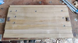
With a viable plane available, I could finish the groove. The main job was just to bring the depth of the groove down low enough that the plane blade is slightly below the surface of the shooting board (so that the whole end of the piece being shot is cut). After that was done, I could plane a bit more off the edge piece to give some clearance for the blade.

The finished groove:

01_finished_groove.jpg

End view showing the reduced height of the right-hand bit:

02_groove_end.jpg

Now that the groove was finished, I thought I'd get on with lining it with this stuff:

03_uhmw.jpg

That's UHMW-PE tape, which is extremely slippery stuff (the same stuff I used on the equivalent groove on my big shooting board). The stuff I've got isn't wide enough to cover the whole groove, so I put two pieces in:

04_uhmw_fitted.jpg

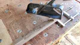
After pushing it into the corners I could trim it with a knife & test the block plane it its groove:

05_uhmw_trimmed.jpg

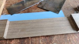
Next up were the various fences etc that fit onto the shooting board. I started off with some lumps of American black walnut, which were Ryoba-sawn and #5 planed until they were square and about the right thickness.

One piece then got a long chamfer along the edge. I wanted this to be pretty close to 45°, so I used a dedicated chamfering plane:

06_chamfering.jpg

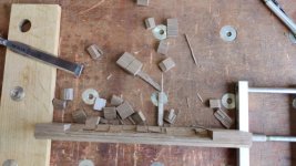
There was then a whole lot of shooting ends square:

07_shooting.jpg

Shooting mitred ends:

08_shooting_45.jpg

and shooting the other sort of mitres (for relief at the back edge of the fences):

09_shooting_relief.jpg

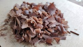
I really like the look of end-grain walnut shavings:

10_pretty_shavings.jpg

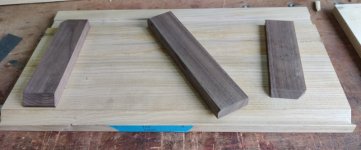
With all the sawing, planing & shooting done, I had these three blocks of ABW:

11_walnut_blocks.jpg

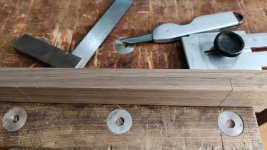
The next job was to mark out what I think would be called a housing; this is for the mitre fence (and the to-be-mitred workpiece) to slide under:

12_marked_out_housing.jpg

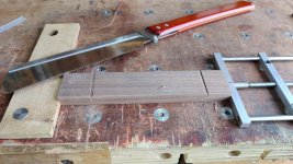
I then made a knife-wall thing with a chisel and then used a dozuki to cut the ends of the housing:

13_chiselled_and_sawn.jpg

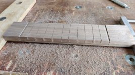
I then did a few more cuts along the length to make it easier to hollow out.

14_more_sawing.jpg

A chisel was used to get rid of the bulk of the waste (apologies for the blurry photo):

15_chopping_blurry.jpg

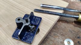
I wasn't really sure how to do a housing like this (I've never cut anything quite like this before). I started by using a recently acquired Record #712 to chamfer one edge of the housing down to the line.

16_chamfer.jpg

I then turned the piece round so the chamfer was at the back and attacked it with an even more recently acquired #10:

17_rebate.jpg

I kept working it down until the mitre fence fitted all the way along the housing thing:

18_checking.jpg

Then cleaned up the surface with some card scrapers (as I couldn't think of a better way):

19_card_scrapers.jpg

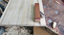
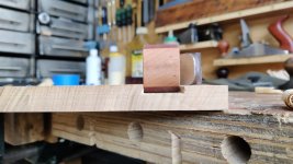
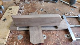
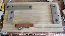
A quick mock up, taking advantage of having two block planes to show the two types of shooting I'll be able to do with this board:

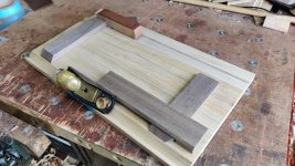
20_mock_up.jpg

Continued in the next post...
 
When do we see a chest to hold all the new planes?! :lol:

But I'm only teasing, it's good to see your enthusiasm for trying things out and making your own solutions. Look a lot of fun.
 
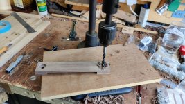
With the fence pieces mostly made, I needed to cut some holes in them for the threaded fasteners that will hold them down and allow a bit of adjustment. The plan is to use low-head cap screws (M6 or possibly M8), with 20 mm diameter penny washers (to spread the load a bit). They need to be sub-flush (as there isn't a lot of space in the front of the tool chest) and the holes for both washer and screw need to be oversize to allow movement when adjusting for squareness.

With all that in mind, the first job was to lug the hand-powered pillar drill out of the dining room, down the garden path and onto the bench in the garage.

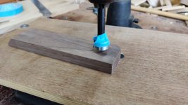
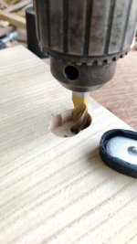
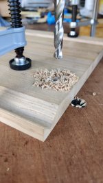
These parts are all quite thin (especially the mitre fence), so I need to be fairly accurate (although not to metalworking precision levels :D ) when drilling the hole in which the washer and low-head cap-screw head will sit. I figured a bit of masking tape on the side of a 25 mm Forstner bit would probably be accurate enough for the purpose:

21_forstner.jpg

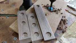
It didn't take long to drill all the holes:

22_forstnered.jpg

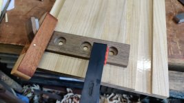
I could then use a 10 mm drill bit (which should give plenty of adjustability for an M6 cap screw, and probably even enough for an M8 one) to drill the rest of the way through:

23_10mm.jpg

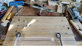
With all the holes drilled, I could then work out where to drill the holes for the threaded inserts in the shooting board itself. To line up the mitre fence, I took advantage of the fact that I'd shot the end of the fence quite accurately using my big shooting board with the mitre attachment. By pushing the fence firmly up against the block plane and making sure there was contact all the way along and across the mitred end, I'm reasonably confident that it'll be in the right place (especially considering there's plenty of adjustability built in):

24_lining_up_mitre_fence.jpg

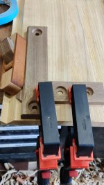
Once that was in place and the hole locations transferred, I could do the same thing to position the mitre support piece:

25_lining_up_mitre_support.jpg

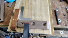
The main fence was quite simple to position, simply using a square to get the nominal hole centres in the right place:

26_lining_up_main_fence.jpg

There are only two things left to do on the shooting board fences:

  1. Drill a hold in the mitre support in the right place to allow Allen-key access to the hidden mitre fence screw.
  2. Drill the blind holes in the shooting board base for the threaded inserts.

These are the only threaded inserts I've got (and they're the ones I used on my big shooting board):

27_threaded_inserts.jpg

I'm wondering whether they're really the best option. The hex-socket at the top (which is used to screw them in place) is relatively deep and hence there isn't that much thread in these (13 mm long) inserts. I'm tempted to look around and see if there are any inserts you can get that are fully (or at least mostly) threaded so that the fences are held more securely in place. I'm also wondering whether I ought to glue the inserts in rather than just relying on the outer thread.

Does anyone have any experience of other types of threaded insert? Any recommendations?
 
AndyT":3cs9kfzj said:
When do we see a chest to hold all the new planes?! :lol:

Eep, that would be a big chest :lol:

I have to admit though: I was having a quite serious ponder this morning about making a box to hold all my (metal) plough planes. Even that could well end up being quite a big box :D

AndyT":3cs9kfzj said:
But I'm only teasing, it's good to see your enthusiasm for trying things out and making your own solutions. Look a lot of fun.

Thanks Andy.
 
Super neat accurate work as always Al.
I promised to show my alternative mitre shooting gubbins, and even thought, I must take some pics when I go to the workshop next time, but forgot before setting off here again. One of these days!
 
I don't know if readymade long inserts exist, but I do know a clever engineer with a lathe, a drill and some taps... ;)
 
Dr.Al":3n3h2hxz said:
the first job was to lug the hand-powered pillar drill out of the dining room, down the garden path and onto the bench in the garage.

I am sure that there is a very good reason for the pillar drill to be in stored in the dining room. Would, though, it not have been easier to take the wood to the drill?
 
Andyp":3v12ikc4 said:
Dr.Al":3v12ikc4 said:
the first job was to lug the hand-powered pillar drill out of the dining room, down the garden path and onto the bench in the garage.

I am sure that there is a very good reason for the pillar drill to be in stored in the dining room.

Lack of space in the garage.

Andyp":3v12ikc4 said:
Would, though, it not have been easier to take the wood to the drill?

Yes, but the first problem with that is the mess it would have made of the dining room (I'm not sure I'd be that popular if I start doing woodwork in the house!) and the second is where it lives tucked out of the way in the dining room isn't somewhere that would be comfortable to work (and it sits on a somewhat wobbly box, which probably wouldn't help make a good hole).

When I eventually move to somewhere with a larger workshop, the hand pillar drill will get a permanent home (possibly next to the powered one :lol: ). To be honest, I mostly use the powered one (it's not as if it suffers from the problems of most power tools, like noise, dust etc). However, I've told myself I would try to use hand tools for anything I could possibly manage on this project in order to prove to myself I could (exceptions I've allowed myself are resawing on the bandsaw and anything involving cutting metal).
 
Dr.Al":3kuzthrf said:
. (I'm not sure I'd be that popular if I start doing woodwork in the house!)

I’ll resist the temptation of sharing an image of my dining table build which was built it it’s entirety indoors using the old dining table as a bench in the kitchen/diner of the house we were living in at the time.
 
Today was a fairly long day in the metal-mangling end of the workshop. It all started with taking the milling machine apart to try to get to the bottom of a temperamental spindle-speed display. I'd assumed it was a result of a vibrating connector on one of the looms that snake their way around the mill. I'd already tried hot glue on the most accessible of them, but I was still having problems so I decided to move the milling machine out and investigate the other end. After moving it and dismantling it, the other end looked fine, so I realised it must be a bad connection on one of the PCBs. Best guess was the display PCB, so I took it out, wicked away all the (lead-free) solder and re-soldered all the joints with leaded solder. After putting it back together, all was sorted and it seems to be working consistently now, even when the mill is a bit vibratey.

With that done, I could get on with the task I was planning to use the mill for.

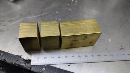
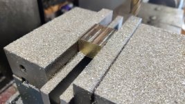
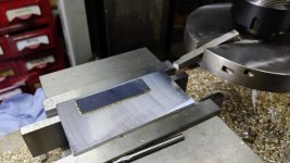
It all started with a lump of 25 × 35 mm brass, which I chopped up into bits:

01_brass_lumps.jpg

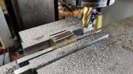
I then went through the three-step process of squaring up the sawn ends with the other four faces and bringing the thickness down to 18 mm:

02_squaring_1.jpg

03_squaring_2.jpg

04_squaring_3.jpg

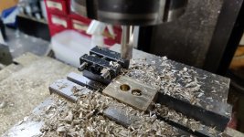
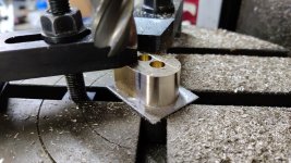
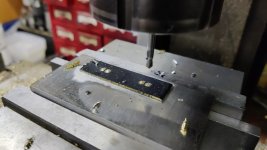
Two 8 mm diameter holes were drilled, 10 mm apart, down to a point depth of about 15 mm:

05_drilling_8mm.jpg

The next job needed my rotary table, which doesn't get used much, but it's very useful on occasion. The first job was to align the centre of the rotary table with the spindle and then zero the axes so I could always refer back to that centre:

06_centring_rotary_table.jpg

The part was then mounted on top of a little scrap of aluminium sheet, using the 8 mm spotting drill in the chuck to ensure that one of the holes was centred on the centre of the rotary table:

07_mounting_part.jpg

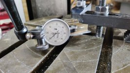
With that done (and the clamps as far out of the way as I could manage), I rotated the rotary table and tweaked it back and forth until a DTI running along the side of the part showed it to be aligned with the X-axis of the machine:

08_aligning_side.jpg

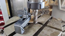
With it aligned nicely, I could zero the rotary table dials and put some pen marks on the table to show me where I needed to stop (it's very easy to overrun!). Then it was just a case of sticking a gert long 18 mm end mill in the chuck and gradually reducing the end of the piece to have a 12 mm radius / 24 mm diameter.

09_milling_round.jpg

10_milled_one_round.jpg

With one end done, I then removed the part, got the spindle back over the centre of the rotary table, fitted the part the other way round, clamped it down, used the DTI to zero the rotary table again, then milled the other end 24 mm diameter.

... and again with the second part, one end then the other.

The parts started off as 25 mm wide but the ends are 24 mm diameter, so there's now a lump in the middle. In theory, I could have milled the sides while on the rotary table, but the clamps would have got in the way and it would have been a pain in the backside, so I decided to use a different approach.

11_rounded_and_lumpy.jpg

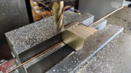
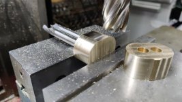
I shoved a couple of 8 mm spotting drills in the holes and used the spotting drills to ensure that the part was aligned with the top of the vice jaw (which I've already checked is level with the lathe axis). It was then quite simple to get rid of the excess 0.5 mm.

12_aligned_for_removing_lump.jpg

Turn it over, rinse & repeat; swap for the other part, rinse and repeat. You get the idea.

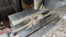
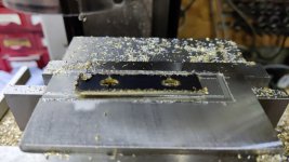
With the outside profile complete, I could hollow out the inside. First with a 16 mm slot drill down to 15.8 mm depth, then with a 19.6 mm end mill (I bought it second hand: I think it's a 20 mm end mill that had been sharpened a few times, hence the reduction in diameter) down to 16 mm depth.

13_hollowing_out.jpg

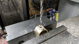
The last milling job on these pieces was to cross-drill a 4.1 mm hole all the way through, 10 mm from the front face of the part:

14_cross_drilling.jpg

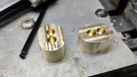
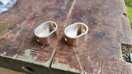
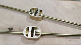
A quick rub back-and-forth on some 180 grit wet-and-dry paper and the back pieces are complete:

15_backpieces_complete.jpg

All of the above (apart from the cross-drilling) could probably have been done in a single setting on a CNC mill and taken a few minutes, but it took me most of the day!

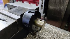
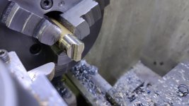
I had a handy little bar of 20 mm round brass, so I faced both ends in the lathe and then put it in a collet block on the milling machine. After finding the location of the end and the centre across the width, I cross-drilled a 4 mm hole all the way through:

16_faced_in_lathe_and_drilling.jpg

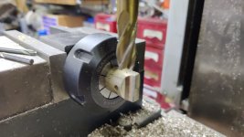
I then turned the collet block through 90° and used a 12 mm end mill to cut a couple of indenty things:

17_milling_finger_grips.jpg

I then turned the bar round in the collet block and did the same two operations on the other end of the bar.

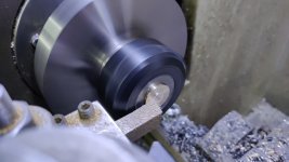
The bar was then chucked in the lathe and the outside diameter turned to fit smoothly into the back pieces I hollowed out earlier:

18_turning_to_size.jpg

After sawing the parts off the parent bar, each then went back to the lathe to have the sawn end faced to length:

19_facing_to_length.jpg

After grabbing a couple of bits of 4 mm brass bar out of the drawer, I could give them a try:

20_ready_for_use.jpg

The plan is to sink the back pieces into the underside of the shooting board and drill a hole into each end of the shooting board. The bar can then be passed through the shooting board end hole and into the back piece. A bit of glue will hold it into the knob thing and then the knob can be moved left-to-right to push the 4 mm bars out of the ends of the shooting board and hence hold it in place in the front of the chest and stop the drawers coming out.

That all sounds very simple when I say it like that, but there are a couple of fairly major challenges to overcome:

  1. How to drill an 18 mm deep blind flat-bottomed hole in a 20 mm thick shooting board. The easy way to do this would be a template and a power router, but I've promised myself I won't do any powered woodwork (apart from bandsaw resawing) on this project, so that's out. A 24 mm Forstner bit on each end will definitely help get it started, but the point of the Forstner bit protrudes quite a long a way, so I don't think I'll be able to go all the way down (at least not without the Forstner bit point coming through the other side). The best idea I've had for this so far is the 24 mm Forstner bit as far as possible on each end of the pocket, then chisels and small router plane to finish it off. If it ends up a bit undercut at the bottom of the hole, it won't really matter.
  2. How to make sure the holes I drill in the ends of the shooting board come out in the right place to mate with the slidey locking things. To some degree I can make that easier on myself by drilling the holes oversize, but there's only so much oversize I can go.

:eusa-think:
 
Today's efforts are likely to fall foul of the swear filter :(

I wanted this project to really challenge my hand tool skills. To that end I had decided that, with one exception (resawing thick wood into thinner wood), I would only use hand tools for all the wood work in this project. What I needed to do next would have been really, really quick & easy with a template and a power router. Assuming a bit of care and a well-made template, I also wouldn't have bug*ered it up if I'd used a power router.

Ah well, here's what I did anyway.

I had today booked off with nothing planned (needed some R&R after a very busy few months at work, and what better R&R could there be than a bit of garage pottering?). I decided the best thing to do would be to try to tackle the daunting task of making the slots for the "locks" that will hold the shooting board into the front of the chest.

These slots need to be 17 mm deep and the wood is only 19 mm thick (I had thought it was 20 mm, but I'd obviously planed it a bit more than originally planned!).

I did a few trial runs on some offcuts. Most of these went badly, with the Forstner bit wandering during the cut (especially the second one). My hand-powered pillar drill isn't exactly rigid and it allows the chuck to move both left-to-right and back-to-front a little. This is not ideal when you're trying to drill a hole right next to another one so the point can't guide the second hole.

Anyway, after about 5 or 6 attempts (during which I came very close to just giving up and getting the power router out), I'd finally managed to come up with a successful method, so I decided to bite the proverbial bullet and start drilling into the shooting board.

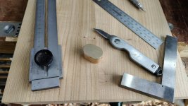
First job was to mark out where the cut-outs needed to be. I did this by using a square & my edge-distance-gauge-thing to get the piece in the right-place, then knifed around it. Finally, I used a fine pencil to make the knife line more visible. This photo was before adding the pencil line and you'll have to look very closely to see the marking.

01_marking_out.jpg

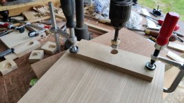
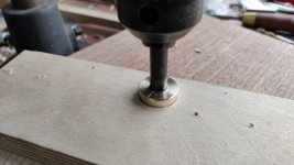
I used the Forstner bit to drill a hole all the way through an offcut of plywood. I also turned a little brass ring, 24 mm diameter (to match the Forstner bit) with a 10 mm hole through (also to match the Forstner bit). That slid over the shank of the Forstner bit.

The plywood piece was very carefully lined up with the marked out slot and then everything was clamped in place:

02_forstner.jpg

As the Forstner bit went into the cut, the brass piece was pushed into the plywood template and helped stop the bit wandering around. Inevitably the waste wood eventually started pushing the brass alignment piece up, at which point I retracted the drill, cleaned all the waste wood out and then carried on drilling.

03_brass_forstner_close_up.jpg

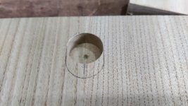
After the first step was complete, this is what it looked like. All good so far:

04_first_step_complete.jpg

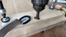
The second half of the slot was cut in the same way. This is where the plywood template and the brass piece really help: once the Forstner bit is deep enough in the wood that it's no longer in the template, the brass piece keeps it going in a straight line.

05_second_forstner.jpg

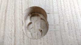
With that done, I had the beginnings of a slot:

06_second_forstner_complete.jpg

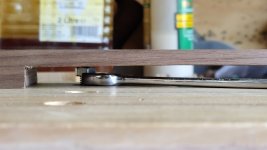
I'd set the pillar drill up so that the point of the Forstner bit wouldn't penetrate through the wood (leaving about 2 mm clearance). That meant that the resulting hole was only about 13 mm deep whereas I needed it to be 17 mm.

To get rid of the bulk of the remaining waste, I grabbed a 12 mm end mill from the other end of the workshop and used the hand pillar drill to make four cuts into the wood, again using the depth limit on the pillar drill to stop about 2 mm before I would have punched through to the other side.

07_end_mill.jpg

The result:

08_end_milling_complete.jpg

From there it was just gouge, 10 mm chisel and the mini router plane (which is much less enjoyable to use than the big ones are!)

09_gouge_chisel_router.jpg

The first one came out really well:

10_one_looks_good.jpg

Test fit:

11_test_fit.jpg

The second one seemed to be going really well until it was time to use the router plane, at which point there was a nasty bit of tear-out (which I didn't notice until after I'd blown all the chips away):

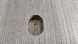
12_arse.jpg

That dark bit is my bench showing through. :( :cry:

This is what it looks like from the other side:

13_arse_2.jpg

:cry: :cry: :cry: :cry: :cry: :cry: :cry: :cry:

That probably wouldn't have happened if I used a power router and a template :cry:

I haven't figured out what I'm going to do about that yet. I guess I could try and find a thin-ish piece of wood with a matching grain (I'm not sure how easy that would be given the colouring of the wood) and set it into the shooting board side of the panel. Or I could try to shove something in from behind (under the brass locking thing), but I suspect that would look rubbish. Or I could just make a new main shooting fence that's a lot wider and hence covers the hole.

Any and all other suggestions are very welcome.

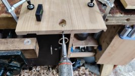
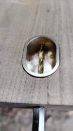
Rather than just wallowing in self-pity, I thought I'd have a go at drilling some holes. After marking out, I drilled a 5 mm hole into from the end into the pocket. On one end (the same one as the breakage!), the drill started slightly off where I'd intended, but I was able to persuade it back into the right place so it ended up okay.

14_drilling.jpg

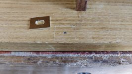
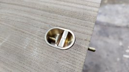
I then inserted the brass bit and used a 4 mm drill bit to mark where the continuation of the hole needed to be:

15_drilling_2.jpg

The 5 mm drill bit then went back in to give a bit more depth & clearance at the back.

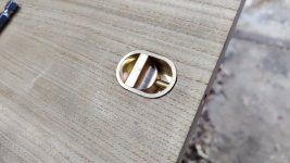
With that I could do a little test and see what it looks like locked:

16_locked.jpg

and unlocked:

17_unlocked.jpg

Note that the pin isn't attached to the knob yet (it'll eventually be glued in place with Loctite 603) , so for now unlocking it is just a case of pushing on the end of the pin and then sliding the knob to match!

That's it for now. I guess I've got a few days to ponder (and despair!) on what to do about the breakage.
 
Don't beat yourself up too badly. A spot of filler, or sawdust and glue, is what I would use. Maybe followed by a bit of dirt!

If your intention was to stretch your skills, you'll have learned a lot. And if you got all the tricky bits right first time, would they even count as tricky?
-----

If you want a really complicated "fix", could you back each of the inserts with a disc of 2mm thick brass, bigger than the inserts all round, so as to make a shoulder. Solder them onto what you have, or mill fresh ones out of solid if you really must!

Drill matching 2mm deep holes from the other side of the wood.
 
I'll be absolutely honest, Al, and say that I am not sure what you are trying to achieve. Therefore, the following might be miles off the mark. Is there any mileage in just making it a through-hole/ slot thingy?

Or, is there a lot of work invested in the piece of wood in which the mistake has occurred, and if not, couldn't you just scrap it and have another go? Or could you slice off a piece which includes the break-out, and edge-join a new piece in?
 
I assume you're going to be gluing the brass pieces into the slots - if so then I'd be tempted to just mix up some glue and sawdust, put it in the slot under the brass piece, let the excess squeeze out through the hole, then clean it up from the other side to make sure everything stays flush.
 
Thank you Andy, Andy, Mike & Stephen for the suggestions (and also to Malc, who replied by email rather than on the forum).

I'll have a ponder during the course of the week. In direct answer to Mike's comment, there is quite a lot of work that's gone into it (mainly just preparing the large panel and then ploughing two grooves, one at 45° which was a bit complicated). There's also the issue that cutting these holes was really quite difficult, so there's every chance I could mess it up on the new one if I just started again :lol:

When I did the CAD model of the shooting board, I drew it with the brass bits going all the way through (which would have been much, much easier!) - you can see the holes in this image I shared in an earlier post:

file.php


The reason I decided to make them blind is that I figured it would be difficult to make the brass bits exactly the same thickness as the wood and with them going all the way through I would never be able to skim the shooting board surface with a smoothing plane in future (I don't think my smoothing plane blade would like meeting a bit of brass part way through the cut).

My gut feel at the moment is that the solution I'll be happiest with would be the decorative Dutchman that AndyP suggested. Given the brass insert lies exactly on the join between the two pieces, I could even try fitting a butterfly / bow-tie type affair over both of the brass knob things and make it look like it was deliberate reinforcement :D

They'd end up being partially hidden by the two fences, but that's not the end of the world.

The Dutchman / graving piece idea also has the advantage that I've never used one before and it would be good experience.
 
Although we tend to think of a dutchman as a butterfly, and I am sure you would relish the challenge of making one, in my mind I was imagining a simple contrasting circle. Much easier to make and fit too.
 
How about six thin felt pads/feet, you would only need four but the two extras could cover the area under the brass thingies.
The problem with a Dutchman style infill is it will only be 2 mill thick in places, doable but fiddly.
Ian
 
Have a play around with fine saw dust and CA glue, my old French polisher used this method. He would get you to stop the repair, if you didn't know where it was originally you wouldn't see it.

Sent from my Redmi Note 9S using Tapatalk
 
Cabinetman":1r5eqo4f said:
How about six thin felt pads/feet, you would only need four but the two extras could cover the area under the brass thingies.

The problem with that is the felt pads would be on the working surface of the shooting board: the top surface in the CAD model view posted above. At least two of them would be in the groove in which the plane runs!

Cabinetman":1r5eqo4f said:
The problem with a Dutchman style infill is it will only be 2 mill thick in places, doable but fiddly.
Ian

Yep, as if the idea of a Dutchman isn't hard enough already :lol:

I had thought that, if I do an infill, I'd make the piece quite a bit thicker and then saw/plane it flush afterwards. Perhaps it won't be as fiddly that way, although what do I know?! It's not like I have any experience of such things :D

Andyp":1r5eqo4f said:
Although we tend to think of a dutchman as a butterfly, and I am sure you would relish the challenge of making on, in my mind I was imagining a simple contrasting circle. Much easier to make and fit too.

I can see that it would be much easier to fit (drill a hole with a Forstner bit, glue piece in), but I'm struggling with the "easier to make" bit. At the moment, I can't think how I would go about making a circular bit of wood of the right size to insert. With a butterfly (or just a rectangle if I want to make life easier), it would just be simple straight cuts and chisel work. Am I missing something obvious?
 
I have made infill discs ( for kitchen hinges) in the past, obviously draw a circle then remove most of the waste, followed by careful rubbing up to the line on a disc sander, or in your case Al with a sanding block by hand, the disc resting over an edge would work quite well I think.
 
Dr.Al":373q4thw said:
Andyp":373q4thw said:
Although we tend to think of a dutchman as a butterfly, and I am sure you would relish the challenge of making on, in my mind I was imagining a simple contrasting circle. Much easier to make and fit too.

I can see that it would be much easier to fit (drill a hole with a Forstner bit, glue piece in), but I'm struggling with the "easier to make" bit. At the moment, I can't think how I would go about making a circular bit of wood of the right size to insert. With a butterfly (or just a rectangle if I want to make life easier), it would just be simple straight cuts and chisel work. Am I missing something obvious?

What :shock: you don’t have a hand powered treadle lathe yet :) . You could perhaps try a hole saw, minus the pilot drill, in your hand powered bench drill.
 
Andyp":3cktdixo said:
What :shock: you don’t have a hand powered treadle lathe yet :) .

I have to admit I've looked at them a few times on ebay :lol: At the moment I've got so little space that it would have to live in the garden, which wouldn't be very good for it I suspect, so that one might have to wait a while.
 
Dr.Al":jihva1pm said:
....I had thought that, if I do an infill, I'd make the piece quite a bit thicker and then saw/plane it flush afterwards.....

The secret to a good Dutchman is to make the sides tapered. Not much, just a few degrees, and that way it wedges in to its own depth and fits tighter and tighter the more you hit it. That technique demands that you make them over-thick, as you suggested, and means you might be re-visiting the hole on the other side to take that back down to the required depth. And make your insert piece first, so that you can mark around it for the hole. It's generally difficult to transfer the shape of a hole to a piece of wood for the Dutchman.
 
Mike G":145yeduv said:
Dr.Al":145yeduv said:
....I had thought that, if I do an infill, I'd make the piece quite a bit thicker and then saw/plane it flush afterwards.....

The secret to a good Dutchman is to make the sides tapered. Not much, just a few degrees, and that way it wedges in to its own depth and fits tighter and tighter the more you hit it. That technique demands that you make them over-thick, as you suggested, and means you might be re-visiting the hole on the other side to take that back down to the required depth. And make your insert piece first, so that you can mark around it for the hole. It's generally difficult to transfer the shape of a hole to a piece of wood for the Dutchman.

Thanks Mike
 
After pondering through the week, I decided I most liked the idea of the decorative Dutchman (even if only as it'll be an interesting experience to try making one). I thought I'd try making it in butterfly shape (as if to reinforce the join between the two boards), but it doesn't really serve any structural purpose: it's just hiding a mistake.

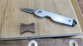
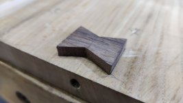
I started by sawing out a minimal sized butterfly. There's a definite and very obvious disadvantage to this in that it won't be fully supported underneath, but considering it won't be structural and that the brass bit will provide that structure, I figured it was worth a shot. If all goes wrong I'll have to make a bigger one.

01_making_insert.jpg

I then chiselled all the edges at a slight angle (thanks for the suggestion Mike). No idea what the angle was (and the sides are almost certainly not at the same angle as it was just by eye, but we'll see whether that's an issue later).

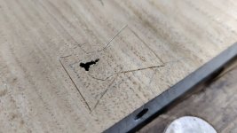
With the butterfly ready, I marked out where it would go with a knife:

02_marking_insert.jpg

You can probably see what I mean by minimal size in the next photo: the crack covers almost the entire width of the narrowest bit of the butterfly:

03_marked.jpg

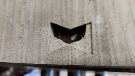
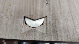
With it marked out, it was a case of attacking it with 10 mm chisel, knife (for the corners) and 4 mm router plane blade until it looked like this:

04_chopped.jpg

Here the disadvantage is clear: the top half of the butterfly will be unsupported, as is the sweet chestnut overhang against which I'll be forcing the butterfly. My plan there is just to epoxy the brass piece in first so it looks more like this:

05_chopped_with_brass.jpg

That does mean that I won't have much excess depth for the taper on the butterfly to help make a tight joint, but again I'm falling back on "suck it and see". If it all goes wrong there will be a plan B available I'm sure.

A quick test fit (not pressed in very hard as I wanted to be able to get it out again without breaking anything!)

06_light_test_fit.jpg

I'd hoped to get some of the gluing done tonight given the long cure times, but I had a pounding headache and figured it was probably better to do relatively irreversible things when I'm feeling a bit fresher.
 
I wonder if that butterfly might look a bit more structural if it had a partner at the other end of the board?
 
Mike G":ib2qig65 said:
I wonder if that butterfly might look a bit more structural if it had a partner at the other end of the board?

Yes, probably. I'd originally cut two of the butterflies out, but I snapped a corner off one of them while paring the angle on it so I thought I'd just carry on and finish cutting the first one and, if that goes well, think about the second one afterwards.
 
Welcome to the next instalment in this rather slow but someone epic toolchest build. Are you sitting comfortably? Then I'll begin.

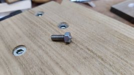
I'd investigated a few other types of threaded fastener, but in the end I decided to stick with the ones I had. I did a few careful measurements and I think I should be able to use standard length M6 low-head cap screws and get a decent amount of thread engagement in the insert.

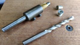
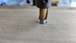
To that end, I started by collecting some hole-making tools: a 9 mm drill bit and a counterboring tool with a 9 mm alignment piece and a 13.5 mm cutter:

01_hole_making_tools.jpg

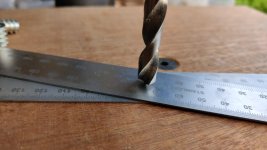
To set the depth on the hand pillar drill, I extended the quill as far as it would go and then lowered the head down until the drill bit just touched a couple of 1 mm thick steel rules.

02_setting_depth.jpg

There was a brief interlude while I sharpened the drill bit and then I proceeded to drill all the holes...

03_drilling_9mm.jpg

... and then counterbore them. I didn't use a depth stop for counterboring, I just turned the pillar drill's handle until the counterbore started to cut, then turned it 10 more times (based on experimentation on the first hole) for consistency.

04_counterboring.jpg

That left the counterbore deeper than the head of the threaded insert, so I'll still be able to take a very light smoothing plane pass if I want to later.

To help get the inserts started (and to compensate for a small fillet on the inside of the insert), I put a 12 mm countersinking bit into a hand drill and chamfered the 9 mm hole slightly. I could then screw in the inserts using a t-handled non-ball-end hex key (to help ensure they went in straight).

05_all_holes_drilled_cb_and_csk.jpg

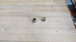
That left one more hole to be drilled: an access hole to get at one of the screws in the mitre fence. To locate that, I turned a (not especially sharp) point on a bit of M6 threaded rod and then superglued a nut to it:

06_locating_screw.jpg

That got screwed into the relevant fence-mounting hole and then the mitre support got attached and a spanner was used to raise the locating screw until it dug into the mitre support:

07_locating.jpg

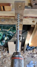
I then went with the relatively quick option of a brace to drill the hole (starting from one side and then finishing from t'other):

08_drilling.jpg

Time for a test fit:

09_test_fit.jpg

I think that's everything done on the shooting board now, except for gluing in the lock pieces and the Dutchmen. Note I said "men". Before carrying on, I made another butterfly thing and used the same method as posted yesterday (chisel, knife & router plane) to cut out the shape on the other end of the shooting board. I didn't take any photos of that process.

The first things to get glued in are the brass pieces. To help press them down firmly, I drew round them on handy bit of wood and cut the shape out very roughly with a coping saw:

10_clamping_pads.jpg

I then coated one side of each clamping pad with parcel tape to help keep it from sticking to the brass.

A couple of bits of plywood were also coated in parcel tape to put on the butterfly side of the board. I'm sure there will be plenty of epoxy that oozes down the sides of the butterfly hole, but hopefully there won't be too much on the face of the board as the parcel-tape covered plywood bits will stop it leaking round the corners.

I also put parcel tape over the hole into which the brass bit will go and then cut round the hole with a knife. That was intended to keep the squeeze-out off the wood and it seemed to work given that I only remembered to do the parcel tape on one of the two holes so I could see how effective it was on the one I remembered vs the one I didn't :eusa-doh:

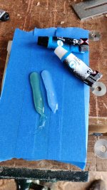
With everything (apart from the missing bit of parcel tape!) prepared, I mixed up some epoxy on some masking tape:

11_epoxy.jpg

Then used the clamping pads and a handily thick bit of wood to clamp everything down on top of the tool chest (to keep it out of the way):

12_clamping_one_end.jpg

The other end was clamped directly down as I could get access to the underside of the toolchest at that end:

13_clamping_both_ends.jpg

If you look at the left-hand end of that picture, you can see the darker area of wood where I wiped the excess epoxy off with some IPA on a rag.

That's going to take a long time to cure now. I'm pondering fitting the butterflies before the epoxy has fully cured (I'll leave it a good few hours before doing so though). Alternatively, I could leave it until tomorrow morning and then fit the butterflies, but then I probably won't get them planed down and the shooting board finished until next weekend. :eusa-think:
 
I don't have anything to add except to say that I am still really enjoying the level of detailed, thoughtful problem solving that you are putting into this.
 
AndyT":1nh2yq12 said:
I don't have anything to add except to say that I am still really enjoying the level of detailed, thoughtful problem solving that you are putting into this.


:text-+1:
 
Lurker":234rq3m0 said:
AndyT":234rq3m0 said:
I don't have anything to add except to say that I am still really enjoying the level of detailed, thoughtful problem solving that you are putting into this.


:text-+1:

Thanks both, much appreciated It's nice to know people are still reading all my waffling and haven't got too bored yet :D
 
Just before coming in this evening, I decided I was going to be impatient (as if you couldn't have guessed that was going to happen :o :lol: ). I took the shooting board out of its clamps, flipped it over and had a look under the parcel tape covered plywood bits. The epoxy that had squeezed out into the butterfly slot was still fluid, but very viscous, so I figured what the heck and scraped the excess out before replacing it with some fresh stuff and attaching the butterflies with clamps:

01_gluing_butterflies_in.jpg

(the other side of the clamp is holding onto the little coping-sawed-out bit of wood, which is pushed up against the brass insert).

Before all that happened, I had some time to kill while waiting for the epoxy to do its thing. I grabbed a random scrap of aluminium out of the drawer and used a flycutter to skim the top surface of it on the mill. I then superglued a bit of thin (1.6 mm) brass to the aluminium and plonked a heavy lump of steel on top of it to hold it down while the superglue cured.

02_flycut_and_glue.jpg

The blue covering on the brass is just a plastic protective sheet thing. I figured I'd leave that on while machining and take it off later.

Once the glue was cured, I drilled four 4 mm holes:

03_drill_4mm.jpg

I then replaced the drill bit with a 4 mm end mill (I don't have any 4 mm slot drills), inserted it into one of the drill holes and then joined the pairs of holes together. I then ran the end mill along the length on both sides of hole, to give to edges parallel with the slots.

Finally, I started milling in the other axis to split the part up and sort out the ends of the pieces, but I'd obviously been a bit over-eager and let it get warm enough to soften the superglue (either that or I was suffering from the fact the superglue is about 5 years old).

04_glue_gave_way.jpg

Not the end of the world though: I'd done the important bit (getting the sides parallel to the slot). I marked the ends with a square and a scriber and finished them with hacksaw and hand files.

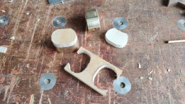
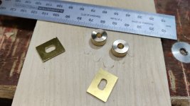
While I was at it, I also made a couple of simple brass bushes: 12 mm OD and 4.1 mm ID.

05_brasswork_done.jpg

I haven't decided whether to use the brass cylinders yet, but if I do they'll be inserted into the end of the shooting board to guide the travel of the locking pin.

The thin brass slotted pieces will be inserted into the sides of the chest to give somewhere for the pins to go (the slots will allow for some wood movement).
 
Malc2098":3kcwdc7b said:
I'm watching/reading. Honest! :)

Me too, although half the time I have little idea of what’s going on but the end results and how how you get there is a joy to watch.
 
Malc2098":2z3ck1pp said:
I'm watching/reading. Honest! :)

Andyp":2z3ck1pp said:
Malc2098":2z3ck1pp said:
I'm watching/reading. Honest! :)

Me too, although half the time I have little idea of what’s going on but the end results and how how you get there is a joy to watch.

Thanks both. Here's another 20 photos for your viewing pleasure :D

Having taken the clamps off, this is what one side looked like:
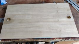
01_one_side.jpg

It's a bit gappy around the edge of the brass, so I guess my chopping wasn't perfect:
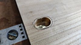
02_a_bit_gappy.jpg

The second side looked like this:

03_second_side.jpg

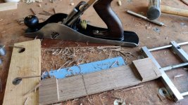
I sawed off the excess with a flush-cut saw, but decided to put it on top of a 1 mm thick ruler rather than trying to cut it flush. I could then clean it up flush with a smoothing plane.
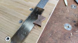
04_sawing_off_excess.jpg

That bout of impatience yesterday showed its ugly head on one of the butterflies: the thin and unsupported bit of chestnut had cracked slightly when I inserted the Dutchman (visible in the top-right of this image):
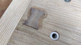
05_impatience_crack.jpg

As there were a few little gaps to fill (including the small knots that I mentioned a month or so ago). I thought I'd try out the sanding-dust-and-superglue method to fill these as they're all quite small. I've tried this a few times before (on oak I think) and not had a lot of success, but I couldn't think of a better way so I thought I'd give it a go.

The first problem was that I've managed so far without doing any sanding (apart from on the hand grip holes on the sides), so sanding dust wasn't something I had a stock of. I grabbed a random orbital disc and a block of plywood and attacked the outside face. I'm not sure I'd want to plane this face now given the presence of the brass, so it was the least impact thing to sand (I might still give it a once over with a card scraper later anyway).

That made a small pile of wood dust, which I carefully swept into a component bag and then stuffed into the various holes. I then dribbled on some (old) superglue, took a photo, then poured some more dust on top and tamped it down a bit with a plastic spatula. I was going to use a bottle of low viscosity superglue I had in the drawer, but it turned out to be significantly higher viscosity than the normal stuff (probably related to the "best before" date of September 2021!).
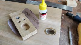
08_sanding_and_superglue.jpg

I did that on all the various holes and left it to dry for a bit. Once I was fairly confident it was fully cured, I rubbed all the bits with my 240 grit sandpaper pad. The results were similar to my previous attempts at sawdust filling (whether with CA or wood glue): a bit meh, but it'll do.
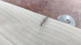
09_filler_meh.jpg

The crack is smoothly filled but fairly obvious:
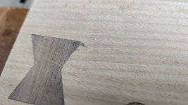
10_filled_crack.jpg

However, once the fence is fitted, it'll be virtually invisible, so I can live with it:
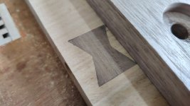
11_mostly_hidden.jpg

I decided I definitely wanted to fit the little brass bushes I made yesterday. To help get them in the right place and with hole that's square to the end, I drilled a 12 mm hole in a bit of aluminium. After fitting both bushes in the hole in the aluminium, I could fit a bit of 4 mm brass bar all the way through the knob mechanism and out through the bushes and the aluminium offcut.

That made sure that the aluminium offcut's 12 mm hole was centred on the axis of the locking bar and, after clamping the aluminium offcut in place, I could remove the 4 mm brass bar and the two bushes.

I then did something that I imagine very few people have ever tried: using an end mill in a drill brace:
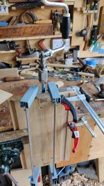
06_end_mill_in_a_brace.jpg

The 12 mm end mill seemed like the easiest way to make a flat bottomed hole of the right size; the aluminium block stopped it from wandering around and hence it made a nice hole. The brace slipped a few times on the end mill (the gripping mechanism on a brace isn't ideally suited to an end mill :lol: ), but it worked:
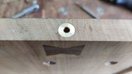
07_bush_installed.jpg

After gluing the bush in with superglue, I put a little bit of 3-in-1 oil on a paint brush and brushed the oil into the brass housing thing, focusing on the 4.1 mm hole furthest from the edge of the shooting board. The oil is there to stop any glue from sticking where it shouldn't.

I used a dressmaker's needle to put a few drops of Loctite 603 in the hole in the knob piece. I then inserted a (cut to length and lightly chamfered) brass bar through the bush and the first hole in the housing. Another drop of Loctite 603 was added to the protruding bit of brass bar and then it was pushed through the knob. A quick wipe with a towel on the exit of the knob and it could be pushed the rest of the way into the housing and left to dry.
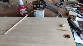
12_oil_and_loctite.jpg

There's a bit of clearance in the shooting board / front relative to the size of the chest. That's to allow for wood movement. To mark the locking pin locations in the centre of the chest, I used some 1 mm thick rules to lift the chest front up slightly. I used another 1 mm thick rule at the top to check the shooting board was equally spaced from top and bottom.
13_lining_up_with_rulers.jpg

After clamping the chest front in place, I then used a small offcut of wood and a persuading stick to push the knobs outwards and make a small indent from the locking pin in the sides of the chest.

I could then empty the chest, stand it up on one end and mark around the little brass sheet piece on the chest (after spending rather a long time hunting around in the pile of plane shavings on the floor after knocking the brass piece off the bench :oops: ).

14_knife_lines_round_insert.jpg

There was no way I was going to get a router plane near that hole, so chopping out the pocket was just a case of taking my time with a 10 mm chisel and skewed end chisel:
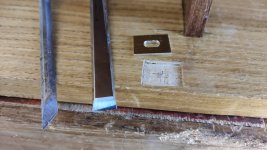
15_chopped_out_pocket.jpg

Once the brass bit fitted nicely, I drew round the hole shape with a pencil and then used a 5 mm chisel to chop out a clearance pocket for the locking pin to go into:
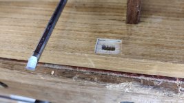
16_chopped_out_mortice.jpg

That was quite tedious as I couldn't lever the chisel far enough over to get the waste out (due to the chest walls getting in the way). In the end I just mashed it up as much as I could and then used compressed air to blow the waste out.

Once the pocket was complete, the brass piece could be glued in with superglue.
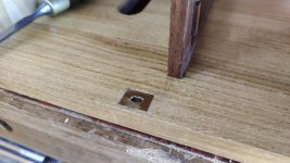
17_glued_in_brass.jpg

Then it was just a case of refitting the drawers...
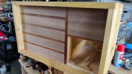
18_fit_the_drawers_again.jpg

... and dropping the front into place:
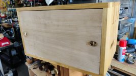
19_front_fitted.jpg

It still needs a going over with a smoothing plane and/or card scraper (probably the latter on the outside face and the former on the shooting board face) and then I'll give it the Mike's Magic Mix treatment.

The next major job to sort out is the drawer handles. At the moment, the only way to get the drawers out is to push them from behind, but I'd like to have something or other to pull on.

There are a few difficulties with this. One is that the mitre support piece and main shooting fence press against the drawers. The main fence is far enough to the left of the chest that it won't get in the way of a centrally mounted knob on the wider drawers. The mitre support piece is more of an issue as it goes across the right-hand drawer (it also goes across the left-hand ones, but again I don't think it'll reach the centre of those drawers so it shouldn't be an issue).

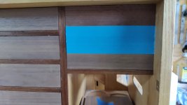
I've marked the "keep-out zone" with masking tape on the right-hand drawer:
20_keep_out_zone.jpg

That feels to me like it covers the most "aesthetically pleasing" location for a knob.

One option is to take Ian's (I think) suggestion and just drill some holes for a finger to go through and pull the drawer open. I won't be able to use the hand pillar drill for that, but I guess that's good for testing my drilling skills :D

Another option is just to offset the drawer pull-thing, maybe mounting something near the top of the drawer.

Another option is to drill or carve an indent into the front of the drawers and fit a knob ends up flush with the front of the drawers. A bit like this image, but with a much, much deeper indent and a much, much shorter knob:

sddefault.jpg


Yet another option would be to make a strategically placed hole in the mitre support piece for the knob to go into when the chest is closed. Whether that's even possible will depend on how the existing holes in the mitre support piece sit relative to where the knob would be.

Any other thoughts?

Another challenge that comes with knobs / pulls is how to make them. I'd originally imagined having a simple rectangular block, as you can see in this old CAD model image:

file.php


That has one significant advantage over a knob in the style of the GR Woodworking image above: I can think of a way to make it! I don't have a woodworking lathe and even when/if I get one, it'll be a powered one as I don't have space for some sort of treadle operated thing (and this project is supposed to be hand-tool woodwork only, so a powered lathe is out).

Again I'd welcome any and all thoughts on this as I'm lacking inspiration somewhat.
 
Well, I like the combination of modern tooling and brace power!

A few random thoughts - hide glue and sawdust works well, but is better on darker woods. I think I would have used a light coloured filler (but I'd have used it a lot more readily than you!).

For handles, you could consider little leather tabs under the fronts of the drawers, which would take up very little space. Or you could turn some pairs of little round brass knobs on your mini lathe. (If you wanted this to be a bit more 'hand tools' you could hold the cutting tool freehand, like Uri Tuchman often does on his most enjoyable YT channel.)

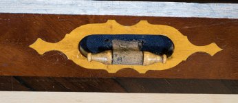
Or else, if you really wanted a challenge, how about this, as seen on one of the drawers in the wonderful 1888 Warrington Chest - a combination of marquetry escutcheon, blue fabric, leather tab and either ivory or boxwood for the turned pull, which is a little over an inch long - don't feel obliged to veneer and French polish everything in sight if you don't want to!

Second back till pull 02.jpg
 
AndyT":31l8o0sp said:
For handles, you could consider little leather tabs under the fronts of the drawers, which would take up very little space. Or you could turn some pairs of little round brass knobs on your mini lathe. (If you wanted this to be a bit more 'hand tools' you could hold the cutting tool freehand, like Uri Tuchman often does on his most enjoyable YT channel.)

Or else, if you really wanted a challenge, how about this, as seen on one of the drawers in the wonderful 1888 Warrington Chest - a combination of marquetry escutcheon, blue fabric, leather tab and either ivory or boxwood for the turned pull, which is a little over an inch long - don't feel obliged to veneer and French polish everything in sight if you don't want to!

View attachment 4

Yeah, I don't think I'll be doing the marquetry thing :lol:

Thanks for the leather suggestion - that's another one for the list.
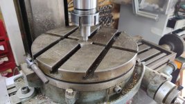
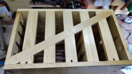
Buoyed by the success (ish) of the butterfly Dutchmen, I thought I'd deal with a longer-standing issue:

01_spot_the_crack.jpg

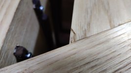
If you look closely at the bottom-left of that picture, you might spot the issue. When I was originally planing the back of the chest back in May or thereabouts, I was working my way up the diagonal with the smoothing plane and the blade caught on the edge of one of the uprights and tore a chunk out. This sort of planing (where two pieces join at such an angle that planing along one grain is planing across another) is definitely not something I've mastered yet. A closer look:
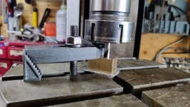
02_closeup.jpg

It's hidden behind the vice jaw thing when that's fitted, but nevertheless it was going to bug me if I didn't do something about it.

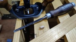
Being on the flat back surface of the chest, access was quite easy with an 8 mm chisel and my beloved router plane. I was very cautious with the down-cuts with the chisel as there's nothing supporting the underside of the uprights, but it went very smoothly.

03_easy_access.jpg

Clamping was a little more awkward on such a small piece; this was the best I could come up with:

04_less_easy_clamping.jpg

I used fish glue so it needs a fairly long time to dry. I'm not sure how busy my evenings are going to be this week, but worst case I'll tidy it up next weekend.
 
Back
Top