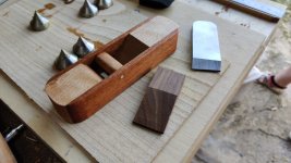
• Hi all and welcome to TheWoodHaven2 brought into the 21st Century, kicking and screaming! We all have Alasdair to thank for the vast bulk of the heavy lifting to get us here, no more so than me because he's taken away a huge burden of responsibility from my shoulders and brought us to this new shiny home, with all your previous content (hopefully) still intact! Please peruse and feed back. There is still plenty to do, like changing the colour scheme, adding the banner graphic, tweaking the odd setting here and there so I have added a new thread in the 'Technical Issues, Bugs and Feature Requests' forum for you to add any issues you find, any missing settings or just anything you'd like to see added/removed from the feature set that Xenforo offers. We will get to everything over the coming weeks so please be patient, but add anything at all to the thread I mention above and we promise to get to them over the next few days/weeks/months. In the meantime, please enjoy!

Holiday Toolchest

Cabinetman":18scud4h said:
Just a quick thought re-the handles, you could save weight and space by having leather tabs instead of handles/knobs?

Hmmm... interesting idea, I hadn't thought of that. It would probably be easier to fit them than what I had in mind. :eusa-think:
 
Conclusion? Well, I think there's probably a law defined somewhere, that as soon as a product is finished enough to be usable, all the development effort that might have finished it off gets diverted onto Mark 2, which is going to be even better...one day! ;)
 
Well, no-one told me off about too many photos, so here's some more :D

If you cast your mind back to the post you'll find at the end of this link, you might remember that I'd found that the angle I put on the top of the planing stops (to help pull the wood down) meant that the back edge was a bit high when planing thin things. I'd been putting off dealing with that as milling steel isn't that much fun in my little mini-mill (one day I'll have enough space for something bigger!)

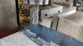
Today I decided to just get on with it and in the end it wasn't that bad at all. I used this big end mill (mainly because it was already in the chuck and I was too lazy to change it):

01_milling_top.jpg

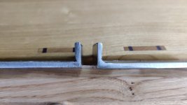
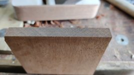
Before and after photo below. As you can see, it doesn't make a huge difference to the thickness (so no concerns about strength), but the top surface will now be parallel to the top of the chest so the plane should clear all (or none!) of the planing stop. It still has the angled teeth that will hopefully help stop the workpiece lifting.

02_before_and_after_milling.jpg

With that done a lot quicker than expected, I thought I'd move onto the next challenge. As you can see in the following photo, the drawers than run on the walnut cross pieces (I think I've called them something different every time I've mentioned them :D ) have drawer stops set into them. The bottom drawer, however, runs directly on the chestnut base and I'd put off thinking about the drawer stops for the bottom drawer... until now...
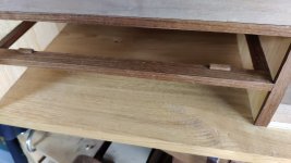
03_missing_a_drawer_stop.jpg

Getting these in the right place could be considered somewhat challenging, but here's how I went about it.

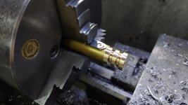
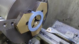
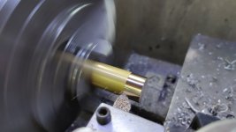
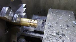
I started by putting a bit of 20 mm brass in the lathe chuck and taking a very light skim cut on the outside to prettify it:

04_skim_some_brass.jpg

I then cut a couple of grooves with a parting tool, mostly as a visual guide for how big I want the parts to be:

05_groove_and_chamfer.jpg

A couple of bits of feeler gauge stock (totalling 1.5 mm) were then put in between the workpiece and one of the chuck jaws:

06_offset.jpg

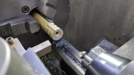
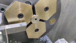
I could then drill and countersink an off-centre hole:

07_drill_and_countersink.jpg

The first one was parted off in the groove line and then I faced, drilled and countersunk the second one before parting that off as well.

The parting tool left a rather shabby face (I've never really managed an acceptable finish straight off the parting tool), so I fitted my home-made brass soft jaws to the chuck along with a 3D printed thingamabob that allows the jaws to clamp down on something while they're machined.

A plunge cut with a 16 mm slot drill started the hole and then I could bring it to dimension with a boring bar:

08_soft_jaws.jpg

The parts could then be pushed against the back of the bore in the soft jaws and I could face and chamfer them. I did both faces of each part in this set-up just to make everything tidy and consistent.

09_clean_up.jpg

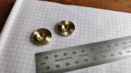
With that, my little custom cams were made:

10_cams_done.jpg

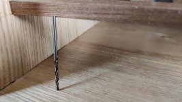
That was the easy bit. The next challenge was how to drill the pilot holes for the screws that would hold the cams in place. Not easy when the chosen drill bit is longer than the gap between the base and the first cross piece, even before you put it in a drill chuck :lol:

11_marked_with_drill_bit.jpg

Given it was only very slightly too long to fit in the gap (and given it's a 2.5 mm drill bit, which is tapping size for M3 and hence I have lots of spares :D ), I sorted out the length by just cutting a bit off the shank with the angry grinder. Now all I needed was a zero-length drill chuck.
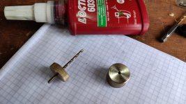
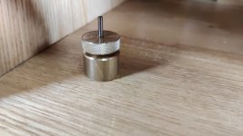
It's handy having a lathe:

12_custom_drill.jpg

The drill bit is glued into the knurled brass bit with Loctite 603; the other piece is just a plain brass piece with a 2.5 mm hole, which serves two purposes. Firstly, by holding it down to the chestnut surface, it makes sure that the drill bit goes in square. Secondly, it acts as a depth stop: when the knurled bit reaches the plain brass bit, I've drilled far enough and it's time to stop.

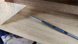
Before drilling though, an awl or a centre punch mark would be useful to get the drill going in the right place. Not a chance I'd fit either awl or centre punch in that gap, so I abused a metalwork scriber:

13_abusing_scriber.jpg

It was then just a case of turning the knurled ring by hand until it reached the stop:

14_drill_until_stop.jpg

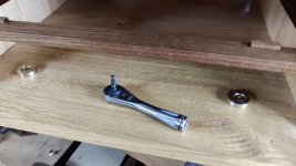
Fitting the parts was quite straightforward as I have a very handy little ratcheting bit driver.

15_screwed_in_place.jpg

Loosening the screws off very slightly allows the cams to rotate and, being eccentric, adjusts the exact place at which the drawer stops.
 
I am beginning to think this whole project is really an exercise in finding as many problems as possible and then solving them - and it looks a lot of fun!

There are so many other ways you could have made bottom drawer stops, that it must be quite frustrating for you having to choose just one :)
 
AndyT":boeu86pf said:
I am beginning to think this whole project is really an exercise in finding as many problems as possible and then solving them - and it looks a lot of fun!

There are so many other ways you could have made bottom drawer stops, that it must be quite frustrating for you having to choose just one :)
:text-lol:
 
The reason I didn't put a packing piece behind the drawer was that I was worried that it would look wrong when the chest expanded / contracted with humidity. If I'm understanding expansion right, then the chest itself will get deeper and shallower as humidity changes but the drawer will stay the same depth regardless. If that's right, then when the humidity changes, the top four drawers will stay aligned with the walnut crosspieces (as the stops are at the front of the drawer). If the bottom drawer was aligned with a packing piece at the back, that one drawer would be misaligned.

Now of course it's a tool chest so it probably doesn't matter, but I thought it best to try to do the best job I can. If nothing else I'll learn more that way.

The reason I didn't use any other method for a bottom drawer stop is simply that this was the only one I thought of :)
 
With all the drawers having their stops, it seemed like a good idea to do a few light passes with a smoothing plane on all the drawers and make sure everything lined up nicely:

01_drawers_planed.jpg

I'm thinking I'll probably oil the drawers next and then think about handles afterwards (although if anyone thinks that's a stupid idea, please do say!) If I use wooden handles, they'll likely be set into pockets (maybe?) in the surface, so the oiled surface would be removed in that area. If I use leather then I guess it'll need a screw or something. Either way, I'd imagine that oiling it now won't be a disaster.

I'll ponder on it anyway and perhaps oil them tomorrow evening. I wouldn't be surprised if I have to tweak the fit after oiling (by planing a little more off the drawer sides and oiling them again) as I'm guessing that the wood will expand a little.

To continue the spirit of avoiding making any decisions until the last possible moment, I thought I'd move onto another big unknown: the shooting board. I don't really know what this is going to look like yet (or even which plane I'll use with it), but it's likely to be made out of sweet chestnut. All my previous shooting boards have been plywood, but I'm trying to make this chest as much as possible out of "real" wood, so I'd like the shooting-board to be the same if possible.

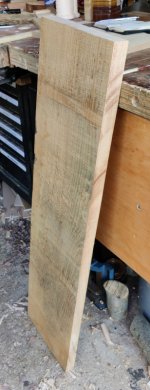
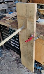
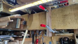
I've got quite a lot of chestnut stored on the ladder racks above my head in the workshop, so I picked one of them, slid it part way out and (with some clamps and a bit of walnut that was a convenient size attaching the hanging-out piece to a joist), attacked it with the big ryoba:

02_sawing_overhead.jpg

That might look like a slightly daft way to saw, but it's actually quite comfortable for someone of my height. Having the to-be-cut-off piece attached to the joists means everything's nice and stable and vibration-free as I cut and nothing moves at the end of the cut, which is always nice!

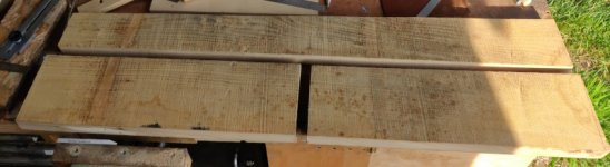
That gave me a length of chestnut to play with:

03_cut_off_piece.jpg

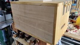
Now I need to decide what to do with it. It's probably not quite wide enough to form the chest front as a single piece (although if I were very careful, I might just get away with it). However, that piece I've cut off is twice as long as it needs to be and quite a lot wider. Therefore, one option is that I can cut a slice off it that's half the required width, cut it in two lengthways and then join the two pieces together to get the width I want.

Alternatively, I could cut it in half lengthways and then resaw one half into two pieces and unfold/bookmatch it.

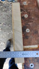
It's currently a little over 35 mm thick. The grain is perpendicular (effectively quartersawn?) in a lot of the width (probably most of the width once it's been trimmed down to half the height of the chest), so it should be nice and stable, which seems like a good feature for a shooting board.

04_end_grain.jpg

My completely made-up-in-my-head idea of the shooting board was going to be based on a 20 mm thick base. There's obviously no way I'd get two 20 mm thick pieces out of that if I resaw it in half, but I expect I'd manage 15 mm and that might be enough.

It would probably help if I'd decided what the shooting board was going to look like :lol:
 
After pondering a bit overnight, I decided that the best option would be to split the board in half lengthways and join the two ends together, rather than trying to resaw & bookmatch. That way I can shoot (pun intended) for a 20 mm thickness for the shooting board. If I later decide to drop that to 15 mm, it's going to be a lot easier than starting at 15 mm and then trying to make it up to 20 mm!

As I knew I was going to use both ends of the wood, I started by ripping the width down with the big ryoba (so I end up with one long offcut rather than two short ones):

01_ripping.jpg

I then chopped the wider piece in half:

02_ripped_and_chopped.jpg

One of the ends sat quite flat on the bench (so not too twisted) but the other wobbled all over the place, so obviously had quite a lot of wind. I thought I'd deal with the twisted one first and save the easier one for later.

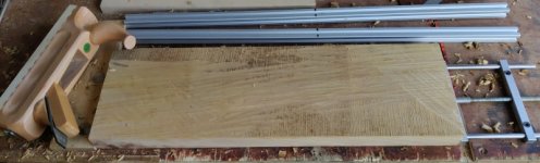
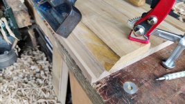
I started by attacking on side of the board with the scrub plane. I wasn't aiming for any particular amount of coverage or anything else, I just kept taking more off until, when flipped over, it would sit on the bench without rocking:

03_scrub_flattening.jpg

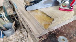
I could then use the scrub plane to get the other side flat enough that it looked good when sighted along the winding sticks:

04_scrub_flattening_other_side.jpg

Once that was done, I gave the whole surface a once-over with the scrub plane in preparation for some more elegant work with the #5:

05_scrub_overall_pass.jpg

That's it for now; it was getting very hot in the workshop despite being only 10am and I decided it was time for a tea break :)
 
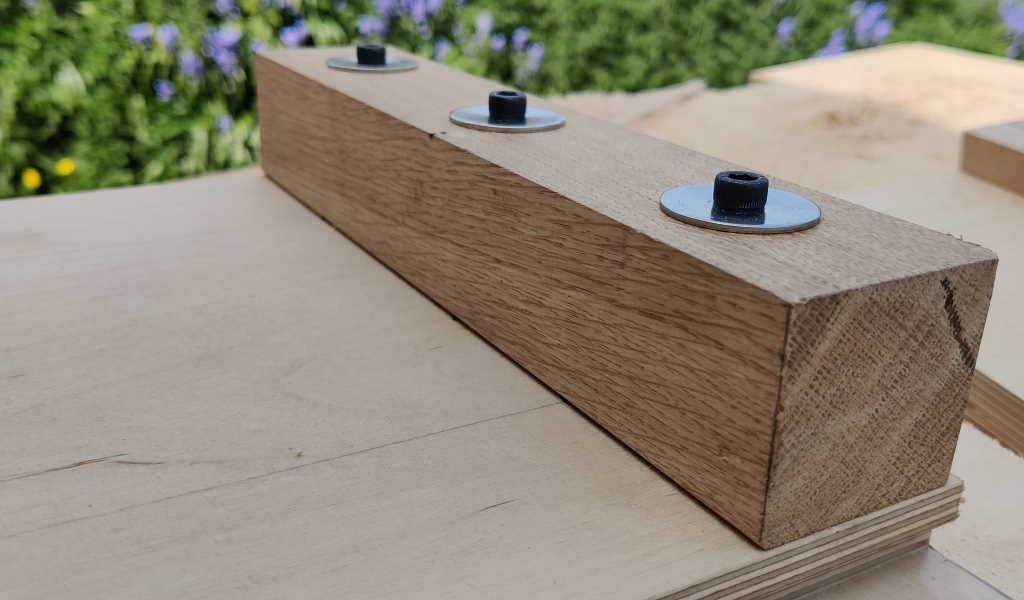
I wise man (I think it was Bugbear) once told me if you can’t make it accurate make it adjustable. Very true for shooting boards. I think his design called for the fence to be bolted to the board with two bolts. One fixed bolt the other in an enlarged hole, enough to allow a little movement.
 
Andyp":2vzavfhw said:
I wise man (I think it was Bugbear) once told me if you can’t make it accurate make it adjustable. Very true for shooting boards. I think his design called for the fence to be bolted to the board with two bolts. One fixed bolt the other in an enlarged hole, enough to allow a little movement.

Bingo, that's basically how my main shooting board works (although all the holes are enlarged to allow for plenty of adjustment) - more pictures here.

shooting_board_fence.jpg


The travel toolchest one will at least in some ways be based on my main one as it works really well (and is very easy to adjust to be bang-on square), although at least it'll only be used on much thinner boards so that should help.

The challenge is to make it work as well while also being a lot smaller & thinner and using a smaller plane.
 
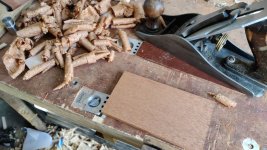
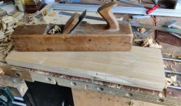
Progress has been slow as a result of the heat, but I did manage a little bit of workshop time first thing this morning. I finished off planing one side of each of the planks. I decided to use a wooden jack plane for a change, partly because it's a lot lighter than my Axminster #5 and every little helps in this heat!

a_lighter_jack.jpg

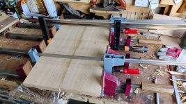
I then planed the edges square and fed the two planks through the bandsaw to reduce them to a bit over 20 mm thickness. As it was getting very hot already, I decided that rather than planing them to thickness, I'd just glue them together and deal with them once the weather's a bit more civilised:

clamps.jpg

It'll be a first for me trying to evenly thickness a board that wide (especially since I really need it to be good and flat to work as a shooting board base).
 
Will you be adding something nice and slidey for the plane to run along? Someone around here added a strip of formica.
 
Andyp":1sue6f21 said:
Will you be adding something nice and slidey for the plane to run along? Someone around here added a strip of formica.

I hadn't really got that far in thinking, but probably, yes.

My big shooting board uses UHMW-PE tape, which is super slidey, so that's a likely contender.
 
I wonder how many photos of bits of wood pre- or post-surface planing there are in this thread so far :eusa-think:

Here are some more :lol:

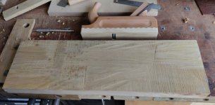
It was a bit cooler this morning (probably helped by being in the workshop by 7am :) ). I took the panel out of the clamps and smoothed off the bandsawn side (with scrub plane, wooden jack plane, Axminster jack plane and Stanley smoothing plane, just because). That side was looking generally quite nice, so I used it as a reference for the marking gauge and worked the original side down to thickness.
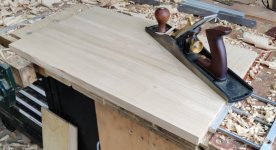
01_plane.jpg

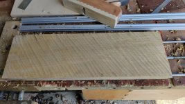
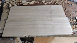
What was once the bandsawn side:

02_planed.jpg

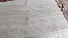
There are a few knotty things in the panel, which I'm not sure what to do about:

03_knotty_things.jpg

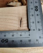
I was thinking this would be the outside face of the chest front, and hence the underside of the shooting board (i.e. no grooves to cut in this face or anything else really), so I don't have to worry about ploughing through those knots, but I'm wondering if it would be a good idea to blob a bit of superglue or epoxy into them before applying finish. Alternatively I could just rely on Mike's Magic Mix to gloop up the holes a bit. I'd welcome any thoughts. This is the biggest of the knots/holes - as you can see it ain't huge:

04_close_up.jpg

None of them are visible on the other side of the panel (although I guess that might change when I plough a groove for the plane to run in).

The other side is a bit more colourful thanks to that yellow staining, but I don't really want to make it any thinner than it currently is (about 20 mm).

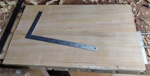
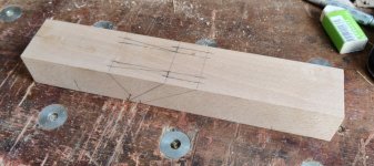
To finish off today's fun, I marked up the approximate size ready for sawing out:

05_other_side.jpg

The dimensions of that rectangle are a bit on the large size: I figured I'd saw to those lines and then plane to fit. I guess I'll have to reduce the width of the board by a few millimetres compared to the close-fit size so that I allow for wood movement.

I'm not going to manage any more today I don't think: I've got to get in a taxi in a few hours to go to Heathrow for a work trip to Hong Kong. Last time I went (back in March), I caught covid and felt awful for a week afterwards, so I'm really hoping that experience won't be repeated :(
 
Re the little holes, my first thought would be to say leave them, it's a toolchest not a jewellery box. But I can feel your uncertainty - the standards elsewhere on this piece are so high - so I think something else is in order.

The simple option is to use whatever filler you have to hand. This could be epoxy or a mixture of sawdust and any glue. I'd probably use some Brummer Stopping but just because I have a tin and it lasts for years, generally setting like a rock long before it's used up.

The snag is that no filler will stay matching the colour of the surrounding wood.

If that bothers you, the most labour intensive option would be to cut back the holes with a chisel and insert little patches of the same wood, with the grain pattern matched and lined up.

I think they are a bit too big to rely on the finish to fill in.

Hope your trip is ok and hasn't been affected by the floods - parts of Hong Kong had over 150mm of rain in just one hour the other day.
 
AndyT":18lmp70v said:
Re the little holes, my first thought would be to say leave them, it's a toolchest not a jewellery box. But I can feel your uncertainty - the standards elsewhere on this piece are so high - so I think something else is in order.

The simple option is to use whatever filler you have to hand. This could be epoxy or a mixture of sawdust and any glue. I'd probably use some Brummer Stopping but just because I have a tin and it lasts for years, generally setting like a rock long before it's used up.

The snag is that no filler will stay matching the colour of the surrounding wood.

If that bothers you, the most labour intensive option would be to cut back the holes with a chisel and insert little patches of the same wood, with the grain pattern matched and lined up.

I think they are a bit too big to rely on the finish to fill in.

Thanks Andy, that's good advice. I'll have a ponder while I'm bored out of my skull trying in vain to sleep on a 13 hour flight!


AndyT":18lmp70v said:
Hope your trip is ok and hasn't been affected by the floods - parts of Hong Kong had over 150mm of rain in just one hour the other day.

Yes, I'm hoping it's okay. We'll probably ring the local rep before getting on the plane just to get his opinion.
 
Dr.Al":1ln8fofk said:
I haven't had much time near a computer to carry on with the design work, but I did have a nice trip out to Wentwood Timber yesterday. I'd never been there before so wasn't sure what to expect, but I liked it a lot. I'd also been to Bristol Wood Recycling Project the day before (another first), but I'm less tempted to go back there unless I want construction timber (and can face the god-awful Bristol traffic again!). They sold hardwood, but Wentwood was much better value. I did come away from BWRP with some bits of birch plywood and a couple of lengths of unknownium though, including one that looks like maple to me.

Wentwood hardly had any poplar (one short piece, which I bought just to experiment with since it was only £7). They had loads of sweet chestnut though and, despite not having finished designing the box, I couldn't resist coming away with quite a lot of that. I've now got four long planks stored in the garage so I expect that I'll make the chest out of that.

I'm going away on holiday relatively soon and I'm going to have a go at making something or other (possibly just practice joinery) while I'm away. I obviously don't have a tool chest yet so I'll take my portable workbench. It also occurred to me that I have one of these in the shed:


I got this as a result of someone on another forum offering it free to a good home. I don't have a mitre saw any more as I sold it a year or two ago, but I kept hold of the stand just in case it came in handy.

It isn't especially robust, but the mounts for the mitre saw are a good size for holding my portable workbench and it fits behind the front seats in the car so won't be a problem to transport. I'll take it away with the workbench and see how I get on with that combination and it might help guide me in my design of the chest (and possibly a collapsible bench to go with it!) I wouldn't be surprised if I end up finding the mitre saw stand too flimsy as soon as I start chopping dovetails, but it won't hurt to have it with me.
I gave one of those away :)
 
Andyp":33zoqx8p said:
I wise man (I think it was Bugbear) once told me if you can’t make it accurate make it adjustable.

You might be right, but I thought I heard it from Rob (( wood bloke) originally.
 
Lurker":27z9l6xh said:
Andyp":27z9l6xh said:
I wise man (I think it was Bugbear) once told me if you can’t make it accurate make it adjustable.

You might be right, but I thought I heard it from Rob (( wood bloke) originally.
That must be in the very dim n'distant past :lol: - Rob
 
In the long-standing tradition of putting off decisions until the last possible moment, I've decided not to think about filling in those holes just yet. I'm sure I'll fill them with one of AndyT's suggestions, but I don't know which yet so I'll think about it later.

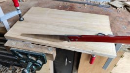
I'm back from Hong Kong now and have had a good night's sleep, so I thought I'd do a bit of gentle pottering along with the shooting board. I started by sawing along the lines (which were placed deliberately to leave the board oversize, so I could just saw directly along the lines).

01_sawing.jpg

I then planed one long edge flat & square and then used it as a reference to shoot the ends to length. I find it inordinately satisfying to produce full-length end-grain shavings on a jointed panel...

02_shooting.jpg

Once it was a close fit end-to-end, I reduced the width of the board until it was a relatively good fit top-to-bottom:

03_tight_fit.jpg

I then took a few shavings off with the #7 until there was a couple of millimetres gap at the top: this should allow for some expansion of the panel.

04_loose_fit.jpg

The next job was to plough a groove for the plane to run in. The idea is that, like my other shooting board, the plane will be constrained on the right so it can't drift away from the board. I measured the width of the webs on the side of the plane and they seemed to be pretty much spot on 30 mm, so I marked out for 30 mm groove, 30 mm (arbitrarily) from the edge of the panel:

05_mark_groove.jpg

As it's quite a wide groove to plough, I wanted to use both depth stops on the plough plane, but my #45 didn't come with the second depth stop. Thankfully, my #55 did and they seem to be the same part, so I could nick it off the #55 :D .

I've never ploughed a groove wider than about 12 mm and was a bit nervous about going straight to 30 mm, so I decided to start with a (home-made) 25 mm blade. Due to the grain direction of the wood, I had to configure the plough plane for left-handed use (I'm going to be ploughing a groove on the other side of the board later, so turning the board round and using the other edge just would have put off the problem for the next groove).

06_plough_groove_25mm.jpg

There was a lot of what I would (as a machinist) call chatter: the blade seemed to bounce along the surface quite a bit making some very strange looking shavings...

07_juddery_shavings.jpg

... and a pretty awful finish on the bottom of the groove:

08_juddery_finish.jpg

I'd set the depth stops for a 4 mm deep groove with the intention of getting it down to 5 mm (the distance from the side of the block plane to the blade) later, so that juddery finish doesn't really matter, but it would have been nice to get a good finish off the plough plane. I'm guessing it's due to the width of the cutter and the lack of support over a substantial amount of its width.

With the 25 mm groove ploughed, I replaced the cutter with a 30 mm one and ploughed the sides down. This cutter took lovely (narrow) shavings, so I guess that confirms the theory that the unsupported width was the cause of the chattering.

09_ploughing_30mm.jpg

With the groove now the right width, I could take it down to depth with a router plane. This has the advantage of guaranteeing that the bottom of the groove is parallel to the surface of the shooting board. It also left a lovely finish, removing all that chatter from earlier.

10_router_finishing.jpg

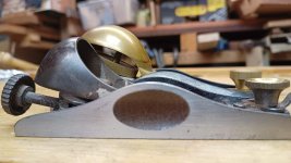
With the groove finished I could try putting the plough plane into it. The web fitted really nicely, but it was at this point I realised that the brass lever cap thing sticks out over the top of the web and hence interferes with the edge of the groove :oops:

11_plough_plane_fit.jpg

I decided that was a good point to stop and ponder on the options. The obvious possibility is to widen the groove to give space for the lever cap. However, if I do that then the only thing stopping the plane from moving sideways (resulting in an out-of-square cut) is the lever cap, which is a long way back from the cutting edge, so that wouldn't work very well.

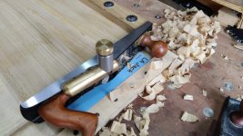
I could widen the groove to the point that it becomes a rebate (i.e. take it all the way to the edge of the panel). That would get rid of any interference issues, but would mean there's nothing to stop the plane wandering to the right and again resulting in an out-of-square cut. The block plane is very light and hence doesn't have a lot of momentum, so it's quite easy for that to happen. I had the problem of planes wandering to the right on my older shooting board and the one in the photo near the start of this post was a complete revelation as it completely removed any chance of drift.

Another option would be to modify the groove to take a 3D printed carrier, a bit like the one used on my existing shooting board:

shooting_board_inserts.jpg


That would require a much deeper groove (to allow for the thickness of the base of the 3D printed carrier). It would also have to be wider. If I did it in exactly the same way as my existing shooting board, it would also require an undercut, but I could probably do without that if the carrier only supported the right-hand side of the plane and not the left.

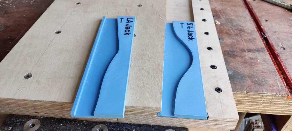
Another really drastic option would be to reshape the block plane's lever cap, something like this:

12_drastic_option.jpg

I'm not sure whether I can bring myself to do that last one though...
 
Well, I can think of a suggestion...

Just to make sure I understand the problem - with your block plane, the difference in width between the iron base and the bulbous brass grip is almost nothing, unlike an ordinary Bailey style plane where the wooden handle is considerably narrower, and so clears the groove you want it to run in.

The ordinary way round this is to have a rebate, not a groove, and this works well for many of us, but I understand your wish to engineer an elegant solution. You like your constrained runway (which works well, so I have read, on the old Stanley 52 chute board/plane combo or its modern Veritas version).

I thought at first that a slimmer profile block plane would be the answer. Here's a photo of my 60½ (one of Stanley's low angle block planes, and my personal favourite) posed in front of a modern block plane that's like yours

IMG_20230916_175112646.jpg

The handle is lower, at about 52mm overall, but it has the same problem - it won't sit nicely in a 30mm groove of any useful depth.

So, I think you have cunningly designed yourself into a corner with two nice solutions.

One is to find a plane of block plane size without the bulbous handle. The obvious choice would be a Stanley No 2 or No 1. They are about the size of a block plane but have an ordinary narrow handle. I don't have one to measure myself, but one of the wealthier forum members might oblige. Maybe one of your tool-hunting trips will provide one? ;)

Here's a recent example of a No2 that sold at auction in August - https://www.davidstanley.com/catalo...antique-and-modern-woodworking-tools-lot-782/. Don't forget to add 22% fees to the hammer price.

But maybe the more realistic outcome is to recognise that you have uncovered a gap in the history of plane making, which will be your perfect excuse to embark on making planes for yourself? You've got the skills and the gear and I'm sure you could produce something to fit the bill.
 
Absolutely fascinating, Dr Al. This is a really excellent thread, a lovely project, and full of ingenious high-quality work.

AndyT":5sliu47r said:
....But maybe the more realistic outcome is to recognise that you have uncovered a gap in the history of plane making, which will be your perfect excuse to embark on making planes for yourself? You've got the skills and the gear and I'm sure you could produce something to fit the bill.

Take that as an order rather than a suggestion :lol:

 
AndyT":2ibpdnm1 said:
Well, I can think of a suggestion...

Just to make sure I understand the problem - with your block plane, the difference in width between the iron base and the bulbous brass grip is almost nothing, unlike an ordinary Bailey style plane where the wooden handle is considerably narrower, and so clears the groove you want it to run in.

That's exactly the issue, yes.

AndyT":2ibpdnm1 said:
The ordinary way round this is to have a rebate, not a groove, and this works well for many of us, but I understand your wish to engineer an elegant solution. You like your constrained runway (which works well, so I have read, on the old Stanley 52 chute board/plane combo or its modern Veritas version).

I should probably just learn to use a rebated shooting board, but I've been so happy with the grooved type that it seems a shame not to at least try to implement something on this tool chest.

AndyT":2ibpdnm1 said:
I thought at first that a slimmer profile block plane would be the answer. Here's a photo of my 60½ (one of Stanley's low angle block planes, and my personal favourite) posed in front of a modern block plane that's like yours

View attachment 1

The handle is lower, at about 52mm overall, but it has the same problem - it won't sit nicely in a 30mm groove of any useful depth.

Thanks for looking anyway.

AndyT":2ibpdnm1 said:
So, I think you have cunningly designed yourself into a corner

I've got to have a hobby :lol:

AndyT":2ibpdnm1 said:
with two nice solutions.

One is to find a plane of block plane size without the bulbous handle. The obvious choice would be a Stanley No 2 or No 1. They are about the size of a block plane but have an ordinary narrow handle. I don't have one to measure myself, but one of the wealthier forum members might oblige. Maybe one of your tool-hunting trips will provide one? ;)

Here's a recent example of a No2 that sold at auction in August - https://www.davidstanley.com/catalo...antique-and-modern-woodworking-tools-lot-782/. Don't forget to add 22% fees to the hammer price.

:o :o :o :o :o :o :o :o :o

I don't think I'm going to be following that approach :lol:

AndyT":2ibpdnm1 said:
But maybe the more realistic outcome is to recognise that you have uncovered a gap in the history of plane making, which will be your perfect excuse to embark on making planes for yourself? You've got the skills and the gear and I'm sure you could produce something to fit the bill.

Plane making is definitely very high on my list of things that I want to do (I've already made some simple grooving planes and I enjoyed that process).

After watching the GR Woodworking block plane video I was already feeling very tempted to have a go at making a block plane. Perhaps it would be good to make one that can also be used as a shooting board plane. I think I'd want to go for a low angle (38° or thereabouts), which isn't something I've seen in a wooden plane before (although I'm sure they exist). I'd also be quite tempted to go all out and skew the blade as well, but perhaps that's biting off more than I can chew for my first wooden bench plane :lol:

Mike G":2ibpdnm1 said:
Absolutely fascinating, Dr Al. This is a really excellent thread, a lovely project, and full of ingenious high-quality work.

Thanks Mike, that's very much appreciated.

Mike G":2ibpdnm1 said:
AndyT":2ibpdnm1 said:
....But maybe the more realistic outcome is to recognise that you have uncovered a gap in the history of plane making, which will be your perfect excuse to embark on making planes for yourself? You've got the skills and the gear and I'm sure you could produce something to fit the bill.

Take that as an order rather than a suggestion :lol:

yes-sir-salute-han-solo-vo6xd3ohh7qfttdf.gif
 
Well, that sounds very positive!

And thanks for the link - I'd not seen that one. And a single iron is all you need for end grain where the shavings have no strength. There is so much good info online about planemaking now, from the last ten years, since YouTube and the hand tool revival became mainstream. But will you go for wood or metal? How could you possibly find out which would be more suitable for your needs???
 
AndyT":18zjz0wu said:
Well, that sounds very positive!

And thanks for the link - I'd not seen that one. And a single iron is all you need for end grain where the shavings have no strength. There is so much good info online about planemaking now, from the last ten years, since YouTube and the hand tool revival became mainstream. But will you go for wood or metal? How could you possibly find out which would be more suitable for your needs???

If I didn't know better, I'd suspect you were trying to goad me into making multiple planes :lol:

I'm pretty sure it would be a wooden one. As much as I like metalwork (and find it easy in comparison to woodwork), I'm not a big fan of milling (vs turning) and also not a big fan of polishing or similar, which I think I would feel obliged to do when making a metal plane. I'm much more inclined to keep learning about woodwork and hence make a wooden plane.

Thanks for the advice about only needing a single iron: that's very helpful. I'm probably going to end up going down a rabbit hole of reading about planes, but perhaps it would be better to just try making one and see what happens. Learn from one's mistakes and all that :D
 
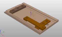
To give a bit of an idea of what I'm aiming for here, this is the current CAD model of the shooting board:

01_model.jpg

The idea is that the groove at the top-right of the image is used for conventional shooting, while the groove at the bottom-left of the image is used for mitre shooting. The perpendicular pieces are the fences for the workpiece to rest against (held in place with screws so that they can be adjusted for squareness), while the strange looking piece with the long housing cut into it will support the left-hand edge of the plane while shooting the mitres.

This is a completely different approach to mitre shooting compared to my existing shooting board, which looks like this:

shooting_mitres.jpg


I don't think the new shooting board is a particularly unusual design of mitre shooting: I'm sure I've seen similar things posted on here before as well as in other places. The main advantage is that it doesn't need a separate assembly (which would have to be dismantlable to fit in the chest).

The only issue is that the 45° groove needs to be quite deep: if it is only a shallow groove supporting the edge of the plane then the top supporting piece would have to be quite high up and that would result in it not fitting into the front of the chest.

That groove was making me feel a bit nervous (hence arranging the wood the grain so that this one would be in the more natural orientation for cutting and the more conventional groove ended up being made left-handed).

After pondering on a few different approaches to making the groove, this is what I settled on...

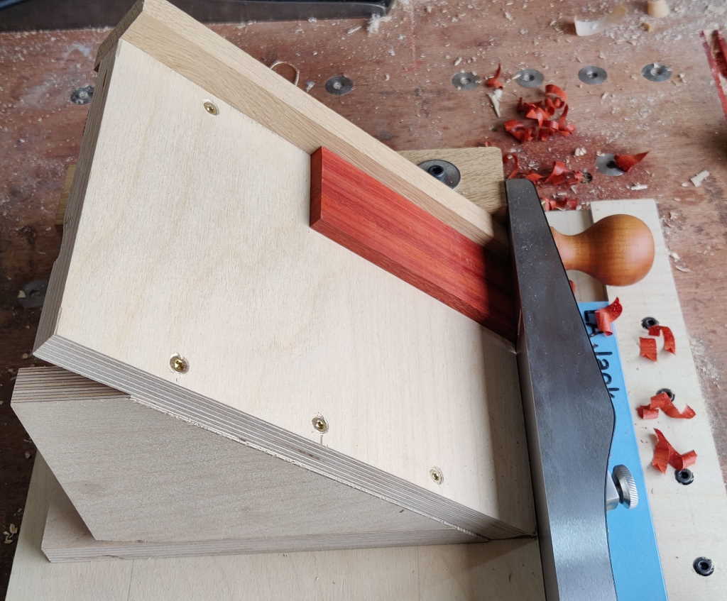
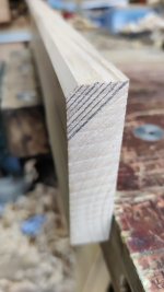
I started with an offcut of sweet chestnut (I've got rather a lot of those now :D ) and planed one side flat and free of twist. I then used a small combination square to draw lots of 45° lines on the end grain at both ends:
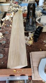
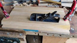
02_marked_angle.jpg

I then attacked it repeatedly with a #5½ until the mitre was complete, then kept tweaking and adjusting (finishing with a #7) until it was at the correct angle and also straight all the way along the board:

03_planed_angle.jpg

This reference piece could then be clamped to the shooting board and I used my recently acquired (from Bristol Design) Record 712 skew shoulder plane to cut the groove.

04_clamped_to_board.jpg

It was quite satisfying to watch the groove progress reasonably accurately along the reference line I'd drawn:

05_following_line.jpg

06_still_following_line.jpg

I kept going until the long side of the groove was 20 mm long (ish). There's enough of a reference surface there now that I should be able to tweak if necessary later.

07_finished_groove.jpg

That left a sharp corner, which was dealt with using the block plane:

08_sharp_corner_removed.jpg

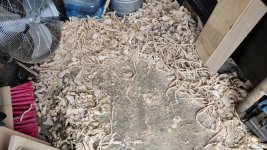
I think it might be time for a tidy-up soon...

09_time_for_tidyup.jpg
 
Going back to the block plane dilemma.

Why be so precious about modifying your own tools to fit your purpose? From my, all be it limited, experience craftsman have been doing that for years. Unless it would be too uncomfortable for use outside of the shooting board I cannot see the problem in reshaping to suit your needs.
 
Andyp":3ozy2tmo said:
Going back to the block plane dilemma.

Why be so precious about modifying your own tools to fit your purpose? From my, all be it limited, experience craftsman have been doing that for years. Unless it would be too uncomfortable for use outside of the shooting board i cannot see the problem in reshaping to suit your needs.

But Al needs an excuse to try plane making!

(Otherwise he could just knock up an alternative narrow lever cap for his block plane that wouldn't foul the side of the groove. It could also have a sideways handle on it.

I only mention this because I'm sure he's already thought of it but doesn't want to disobey orders. ;))
 
Andyp":3ap974hz said:
Going back to the block plane dilemma.

Why be so precious about modifying your own tools to fit your purpose? From my, all be it limited, experience craftsman have been doing that for years. Unless it would be too uncomfortable for use outside of the shooting board i cannot see the problem in reshaping to suit your needs.

That's a fair point, although I'd be quite paranoid about ruining the plane, so I'd be more likely to modify it by trying to make a new lever cap (as the other Andy has mentioned) rather than hacking at a part that might be hard to replace.

AndyT":3ap974hz said:
But Al needs an excuse to try plane making!

As if I need an excuse :lol:

AndyT":3ap974hz said:
(Otherwise he could just knock up an alternative narrow lever cap for his block plane that wouldn't foul the side of the groove. It could also have a sideways handle on it.

I had thought of that but I'll admit to being tempted by the idea of making something from scratch. It's nice to have a few ideas up my sleeve anyway. Now if only I had more time... :eusa-think:

AndyT":3ap974hz said:
I only mention this because I'm sure he's already thought of it but doesn't want to disobey orders. ;))
Absolutely: I wouldn't want to face forum disciplinary action. To show my willingness to comply, there's a copy of this book on its way to me later today... :eusa-whistle:
 
Excellent. I am sure that with Whelan's book, plus videos like the one you linked to (and Stavros Gakos) you'll be well away.
 
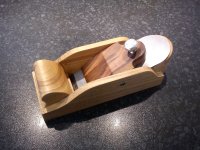
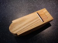
Just a suggestion, but you could make one of these.
DSC03969.jpg
DSC03970.jpg

I did that a few years ago. It now has a fancy brass knob, but these are the photo’ I can access at the moment. It would run nicely in the channel design you are proposing.

Body is a single piece of sycamore. Inset of plum wood underneath. But you could put an angled handle on it, easily.

It’s light and very handy, which I assume is what you are looking for.
 
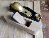
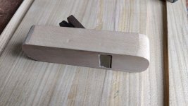
That plane looks lovely @Tiresias. I might well copy that (especially considering how my first attempt went :D ). For which read on...
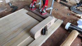
I'm going to call this one a "proof of concept". It definitely needs a lot of work in the execution, but I had to start somewhere.

The John Whelan book is excellent and very easy to read. It offers some excellent advice on how to get started with wooden plane making. In particular, he advises...

  1. Start with a plane you already own and copy the size and shape and general design. That way you can refer to the existing plane for angles and shapes and also be confident in getting a working design at the end.
  2. Start your design by picking the blade and make the plane around that blade.
  3. It's best by far to start with a three-part design (a la Tiresias) and then try a two-part design (basically sliced in half along the length of the plane so a lot of the chiselling becomes sawing) and only when those approaches have been mastered should one try making a one-piece plane.

All sound advice, which I stupidly ignored :)

I started with a block of beech, on which I sketched out some rough dimensions and shapes for the hole (with a 35° bed angle as this is going to be used for cutting end grain).

01_marked_up_beech.jpg

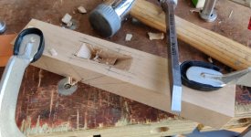
I then attacked it with an 8 mm mortice chisel, taking most of the stock away in the middle (square-sided) bit of the pocket.

02_attack_with_chisel.jpg

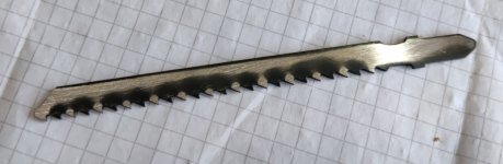
To cut the pocket for the wedge to live, I grabbed a jigsaw blade. My first thought was to try to hammer the set out of the teeth, but they were being stubborn and kept bouncing back, so I gave up and just rubbed it on a diamond stone for a bit until the set was gone:

03_ground_jigsaw_blade.jpg

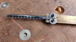
A crude handle was made out of a bit of brass, some filed-down M3 penny washers and a couple of screws:

04_jigsaw_handle.jpg

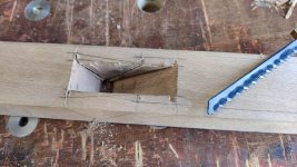
I could then use the jigsaw blade to cut across the grain:

05_using_jigsaw_handle.jpg

I then forgot to take any more photos of the work on the body :? , but it didn't go superbly well. Part of the left-hand side sticky-out bit (abutment?) tore off, so there's not as much wedge support as I would have liked, but I think I'll write that down to experience and consider this a prototype as I implied above.

At some point I decided I really couldn't do much more without a blade to stick in it, so I rummaged in my gauge plate drawer for some 5 mm thick stock. I was somewhat surprised to learn that I don't have any 5 mm stock, so I went with 6 mm thick stuff instead. Possibly a bit daft, but daft is what I'm good at :D

With the 6 mm thick gauge plate roughly bandsawn to size, I milled it to 30 mm thick and then milled a bevel on the end:

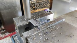
24_milling_bevel.jpg

I then hacksawed off the back corners and ground them into a rough curve. While I was at it, I made two blades: I can either keep two sharp and ready to use or one can be a spare for when I do something stupid and break one of them :)

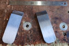
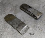
The two blades ready for heat treatment:

25_ready_for_heat_treatment.jpg

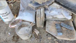
I usually just heat treat steel without much preparation and then deal with all the scale later, but with the blades being quite big, I thought I'd save myself some effort later and coat them in a boric acid/meths mix:

26_prep_for_heat_treatment.jpg

The steel wire is there to help keep the boric acid in place.

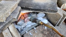
The blades were then heated until a magnet wouldn't stick to them and then they were dunked in some vegetable oil.

27_heating.jpg

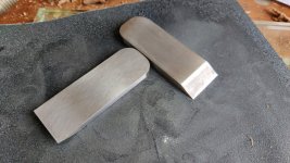
Post-heat treating, they look a lot better than they would have done without the boric acid.

28_post_heat.jpg

A minute or so with some wet-and-dry sorted out what was left.

29_clean_up.jpg

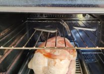
The plan for dinner last night was roast chicken so that seemed a good time to bung them in the oven (with some extra time at a higher temperature after the chicken came out)

30_tempering.jpg

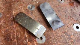
Then it was "just" a case of reflattening (things tend to move when heat treating) and then grinding & sharpening the blade. I've only done one so far in case the tempering didn't work well enough - I can always retemper the other blade with a blow torch if necessary.

31_one_blade_ready.jpg

With the blade ready, I could continue hacking away at the beech block until I had something looking vaguely like a plane. If you look closely, you can see where the "abutment" is a lot thinner on one side than t'other. That wasn't deliberate!

06_much_embuggerance_later.jpg

Definitely not as pretty as Tirerias's one!

It's amazing how big a pocket you need for a 6 mm bevel-down blade & a 35° bed angle:

07_must_try_harder.jpg

I couldn't resist a quick try with a temporary fence held in place with a couple of clamps. It cuts well, but the throat clogs really quickly. That should be easy enough to sort out by shortening the wedge and/or opening the front of the mouth a bit. However, by this point my stomach was asking why I hadn't stopped for lunch yet so I decided to do what I was told.

08_couldnt_resist_a_go.jpg

I'm pretty sure I'm going to start from scratch on the plane body, but I've definitely learnt a few things in the process. The new body should be able to use the same blade, so at least I don't have to do all the milling / heat treatment and grinding again. I bought a big lump of beech from William's British Hardwoods on Friday, so I've got enough for quite a lot more attempts :)
 
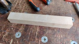
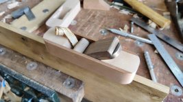
I haven't had much time in the workshop lately, but I had some today so I thought I'd go and have another go at plane making. I decided to re-use the blade and the wedge, but start from scratch with everything else, so I began by getting a bit of beech, squaring the faces up and getting it down to just above the target 30 mm in one direction and slightly wider than the blade in the other direction.

01_planed_beech.jpg

I then got a bit of what might or might not be teak (we've had lots of discussions about this wood on various threads on this site, so I'm just going to call it maybe-teak and leave it at that for this one!). I planed it down to about 7 mm thick...

02_planing_teak.jpg

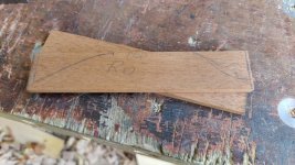
... and then cut a couple of slices off. The marks on this one were from some thoughts about a shape for the plane, but, as you'll see later, I abandoned that plan and went with a simple shape.

03_cut_up_teak.jpg

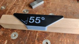
As I'm going with the simpler approach of a three-part assembly, I needed to cut the beech lump into two pieces. I 3D printed a simple marking gauge to help with transferring the angle around the corner:

04_3dprinted.jpg

Note that this gauge gives me a 35° bed angle - I labelled it as 55° as I've printed other similar gauges that give a particular angle away from perpendicular so I thought it was more sensible to keep the numbering scheme consistent.

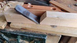
With the lines marked with a knife I could chop it up with my Ryoba and then gradually work down to the lines with a smoothing plane. I also chopped the left-over piece up but at a somewhat more arbitrary angle (probably about 90° from the bed angle). That meant I could have a little play with the layout:

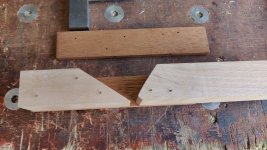
05_playing_with_layout.jpg

That layout results in not a lot of clearance above the cutting edge (for shavings to escape), but I figured it was easier to open it up later than try to close it up.

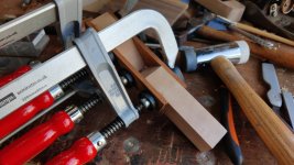
Once I was happy with the layout, I banged a few 1/2" panel pins into the beech and cut them off with some side cutters.

06_panel_pins.jpg

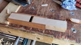
After double-checking I was still happy with the layout, I could then glue it all together.

07_glued.jpg

Once the glue had dried for a couple of hours, I took it out of the clamps and planed the underside and then the two maybe-teak sides.

08_planed_underside.jpg

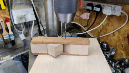
I'm trying to do this toolchest project as a just-hand-tools project, but this plane isn't strictly part of the toolchest, so I decided to cheat and drill the cross hole with the pillar drill.

09_setup_for_drilling.jpg

Note that the photo was taken before lining the drill bit up with the hole location. The bit of beech shoved into the opening was the offcut from the end of the central section. I used my shooting board to bring the length down to be a snug fit in the hole. Having it shoved into the central section served two purposes: firstly it prevented any tear-out when exiting the top maybe-teak piece. Secondly it provided the stock to use as the bit the wedge bears against.

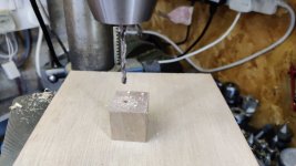
I drilled the hole 3 mm, then opened it out to 3.9 mm. I then took the beech filler piece out and opened the hole out to 4 mm. I'm using a bit of 4 mm brass, which seems to be a very tight fit in a 3.9 mm hole and a somewhat looser fit in the 4 mm hole. Therefore the beech bit should rotate, but the brass should be tight in the maybe-teak.

10_drilling_mid_piece.jpg

With that done, I could rather dramatically reduce the size of that beech piece (with #4 plane for the flat side and rasps / files / sandpaper for the curved side). I also shaped the corners of the plane in much the same way as before and finally took a few skim cuts with the #4½ on the top surface. Once that was done I couldn't resist a quick test:

11_first_test.jpg

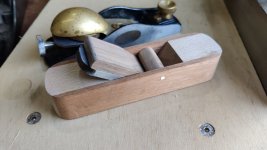
Here it is next to my LA block plane

12_with_block_plane.jpg

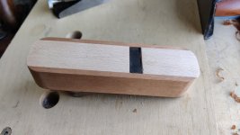
Another view

13_underside.jpg

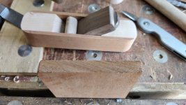
I also tried it out on some end-grain maybe-teak. Before:

14_end_grain_before.jpg

After:

15_end_grain_after.jpg

The shavings were clogging a bit in the mouth, so I opened it up a little bit (I might open it up a bit more later), currently keeping the actual mouth opening the same size & making the wall angle a bit steeper so the shavings can eject more easily.

I then gave it a first coat of the usual stuff.

16_mmm.jpg

It's probably worth noting that the brass bar isn't currently glued in place. It's such a tight fit that it doesn't seem to want to go anywhere without a punch and hammer and I'm inclined to leave it removable for now: it has the advantage of giving me the option of remaking the little beech piece that the wedge bears against if I want to.

I'm sure there's still a lot of room for improvement, but mark 2 seems far superior to mark 1 in my opinion. John Whelan's advice to start with a three-piece construction plane was very good!
 
Wowsers!

Sorry I missed the earlier epic. I'm very pleased and also impressed with the way you have cracked on and made these. :eusa-clap: :eusa-clap:
:eusa-clap:
 
Looks good Al.
How do you hold it in use? A nicely curved and shaped backside would make it more comfortable perhaps?
 
Thanks both.

Regarding holding it & a curvy bum :D , I am wondering about it. For now though, the main aim of this is to be used in the shooting board, so it will be lying on its side. That was the main reason for the curvy corners.
 
Back
Top